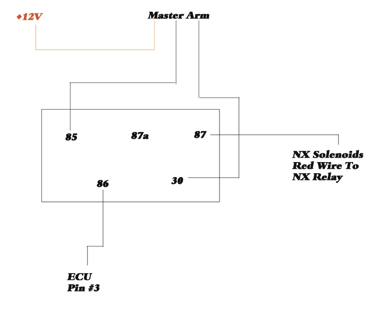
41 Nitrous Relay Wiring Diagram
Nitrous Related Wiring Page 2 Ls1tech Camaro And Firebird Forum Discussion. Nitrous system wiring diagrams dragstuff nos and transbrake ls1tech trans brake express manualzz diagram tci 2 step holley performance products forums leash single stage relay board sniper efi double throw 60 amp pn 15515 question about a mini progressive oxide help creep control camaro firebird forum module dave s. Snowmobile nitrous kits are the best way to make big power! More affordable than boondockers or bossnoss. Nitrous Oxide Kits Systems and components are the quickest and easiest way to get large horsepower increases with a minimum of engine modifications and expense. Nitrous Kits offer serious horsepower at the flip of a switch.
nitrous outlet project: opener wiring diagram filename: opener wiring diagram.ai created date: 08/14/2020 pages: contact information: 2 of 2 rev #: 02 opener arm heater opener purge 87 87a 86 30 85 87 87a 86 30 85 opener relay 1 open close opener relay 2 opener 1 ground battery anel 3 2 2 1 10 amp fuse jumper 10 12 ga 12 ga 10 ga 16 ga 16 ga 16.
Nitrous relay wiring diagram
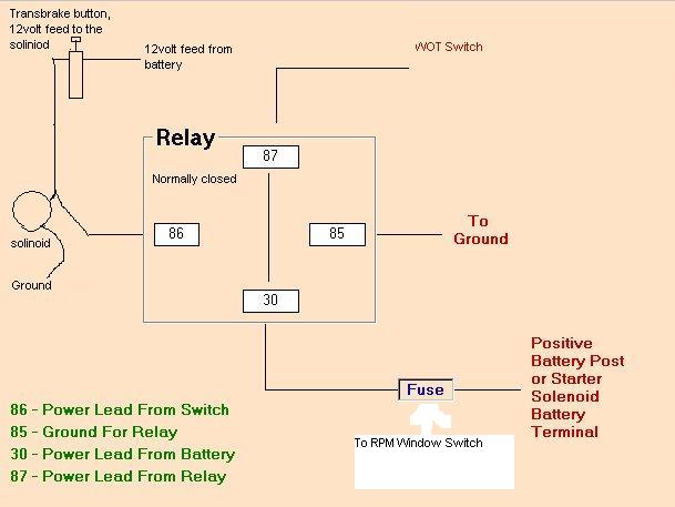
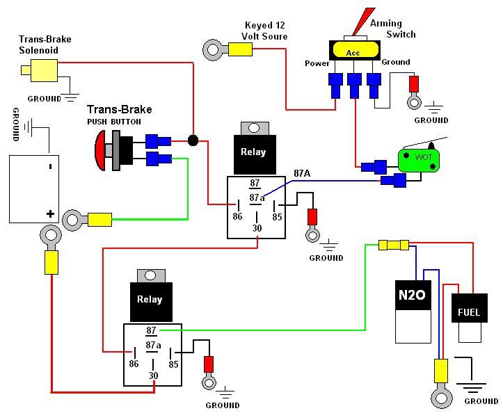
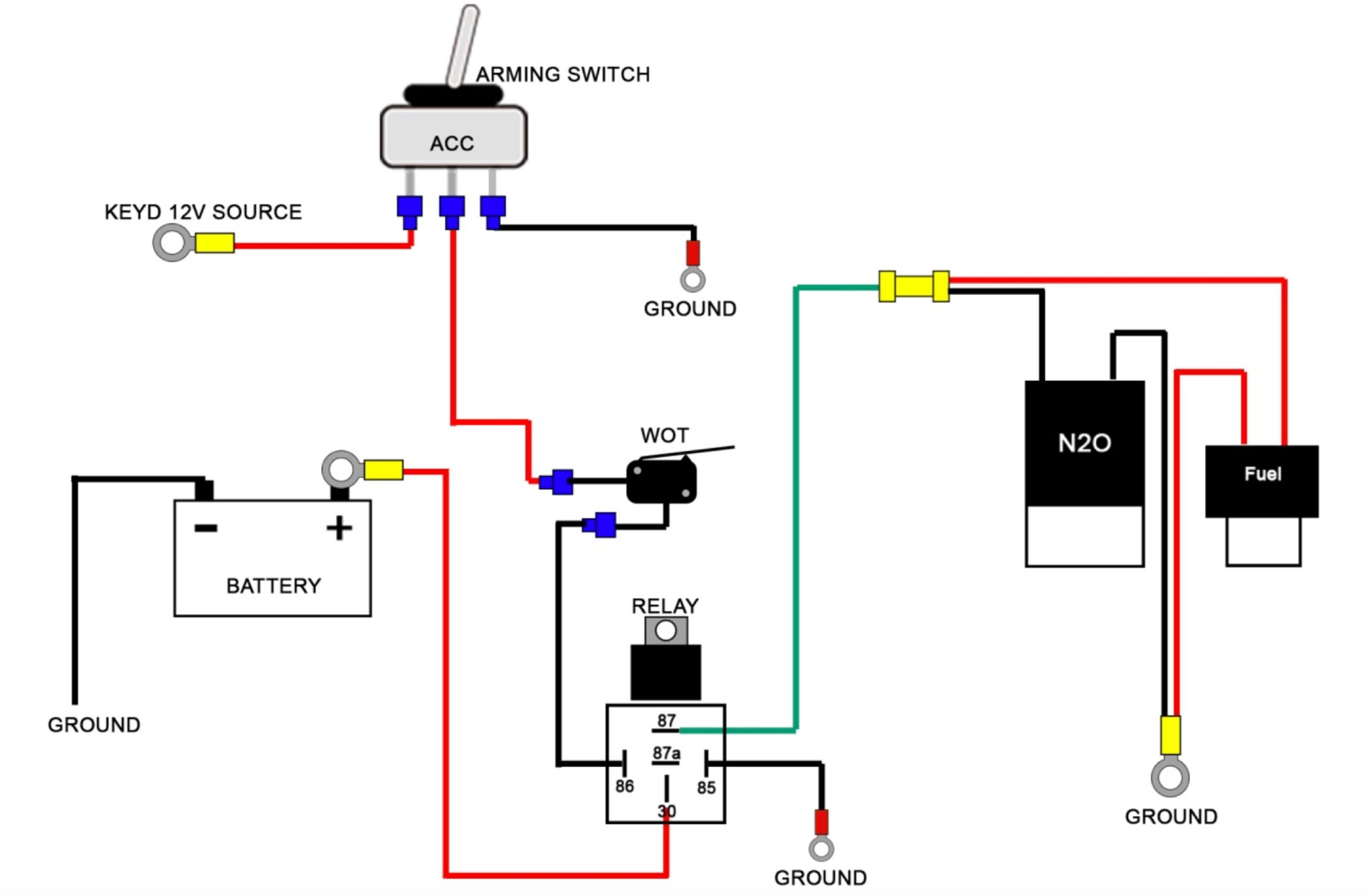
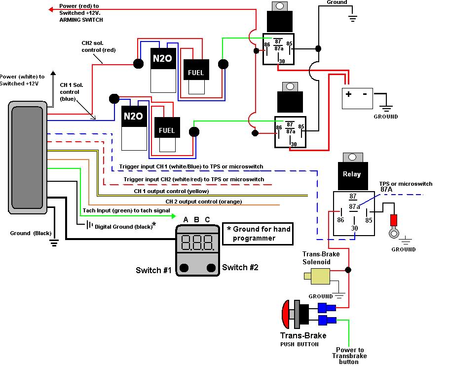
Nitrous Wiring Diagram With Transbrake. The stud labeled "2" is for the transbrake. It is activated by applying +12volts. If you have any questions, email daver@wiringall or call When wired in series with your nitrous system relay it will enable you plished by splicing into the trans brake solenoid wiring and using this power source to. These Wiring Diagrams will help you wire up your Nitrous System or Nitrous Accessory. Includes Nitrous Purge, Nitrous Bottle Heater, and Dedicated Fuel System. Your #1 Source for everything Nitrous. Dealer Locator Account. Toggle navigation 254-848-4300 Speak with a Nitrous Expert M-F 8:30am - 5:30pm CST Call or Text Today!. Nov 17, 2021 · Megasquirt coil on plug wiring
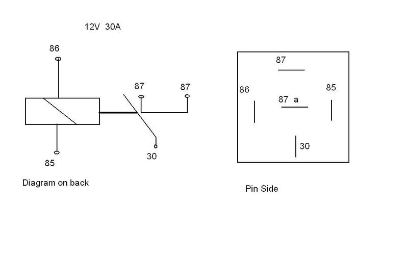
Nitrous relay wiring diagram. Title: wiring diagram Model (1) Author: Dave Created Date: 5/31/2010 9:38:19 PM Jul 19, 2014 · 1) First, Enable the Electric Fan(s) in "Basic I/O" - "System Parameters". Second, enter "Inputs/Outputs" (also in System Parameters), and select the "Output Type" for Electric Fan(s). I prefer it to be a ground output, however, it can be programmed to be either one (+12V or ground). Third, it must be Pin-Mapped to an available J1 connector output pin; click "View Outputs" on the Pin Map. Oct 27, 2021 · Electrical/Lighting/Alarm - Relay help please. - I feel like an idiot for asking this as I should know the answer but I want to use my horn button to power a relay that would switch a low voltage garage door remote. The remote is 3V, I would modify it so it would be switched by the 12V relay. I would have two wires... wiring diagram from your original instructions. Use only the diagram shown in this instruction booklet. The NOS power relay is designed to prevent high amperage current from damaging the control components, such as switches, microswitches, shift handle buttons, etc. The power contacts in the relay will carry a maximum of 30 amps. MOUNTING:
Hi there, I have a question about how to wire up a nitrous system. These are the parts I have. Ford MSD Distributor 8582, RPM Window Switch 8956, MSD 3-Stage Retard Control 8970, MSD High Current Relay 8960 and I want to run this all to a Nitrous System with 100-150 shot. I am also running a 3 Step but I use that for my linelock and trans brake. Mainboard Installation Schematic. 1 Stage Nitrous Using 12 Relay Controller. Nitrous Controller Instructions. 4 Stage Instructions Generic for All Controllers. 4 Stage Nitrous Controller with Main Board and Auxiliary Module Installation Schematic. 3 Stage Nitrous Controller (2 Timed, 1 Instant) with Main Board and Auxiliary Module Installation. Nov 17, 2021 · Megasquirt coil on plug wiring Nitrous Express Nx 16008 Maximizer 5 Progressive Controllers Summit Racing. Tested Nitrous Express Maximizer 4. Car Radio Wiring Diagrams Free 35 Images Delco Stereo Diagram Jvc Pioneer. Untitled nitrous express maximizer 5 relay panel read all instructions before beginning diagram wiring magnetic sdometer cable sensor ez progressive schematic.
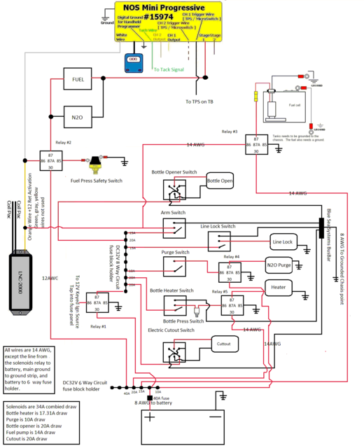
Nitrous Pressure Gauge and Bottle Heater Controller. Part # 15531 (new style) There are two display modes, normal mode, and programming mode. Normal mode: The display will show the current pressure reading from the pressure sensor. When the bottle heater control is armed, it will turn the heater relay on when below the target pressure and off when This manual contains information and diagrams related to wiring most Holley EFI products including ECU's, ignition systems, nitrous systems, water/methanol injection systems, sensors, and more.. If current levels exceed these, use the appropriate relay or solenoid drivers. Do not use improper crimping tools. These Wiring Diagrams will help you wire up your Nitrous System or Nitrous Accessory. Includes Nitrous Purge, Nitrous Bottle Heater, and Dedicated Fuel System. Your #1 Source for everything Nitrous. Dealer Locator Account. Toggle navigation 254-848-4300 Speak with a Nitrous Expert M-F 8:30am - 5:30pm CST Call or Text Today!. Buy Complete Electrics Wiring Harness Stator Coil CDI Solenoid Relay Spark Plug For 4 wheelers Stroke ATV (50cc 70cc 110cc 125cc) Pit Quad Dirt Bike taotao Go Kart By OTOHANS AUTOMOTIVE: Automotive - Amazon FREE DELIVERY possible on eligible purchases
Nitrous Oxide System Installation Help Cold Fusion Nitrous
Nitrous Wiring Diagrams. The stud labeled 2 is for the transbrake. Aem Ems 4 96 Wiring Harness With Fuse Relay Panel 30 2905 96 These Wiring Diagrams will help you wire up your Nitrous System or Nitrous Accessory. Nitrous relay wiring diagram. When wired in series with your nitrous system relay it will enable you […]

Digital Delay Nitorus Boards High Current 2 Stage Nitrous
existing NX relay and plug the Max EZ male plug into your NX relay harness. If your nitrous system does not have a standard NX relay harness, use the included NX relay harness to complete the installation. The following diagrams show installation with popular accessories. Select the appropriate diagram

Boost Leash Wiring Diagram Delima Guesthouse
4,950 Posts. #6 · Dec 23, 2005. If you get no where with this PM me, I have a diagram get me your email and I will send it out or if you tell me every componet for the nitrous your running I can custom build a diagram for yor application. progressive, trans brake, retard module Etc. Or post this In the Electrical section Sparky will take care.
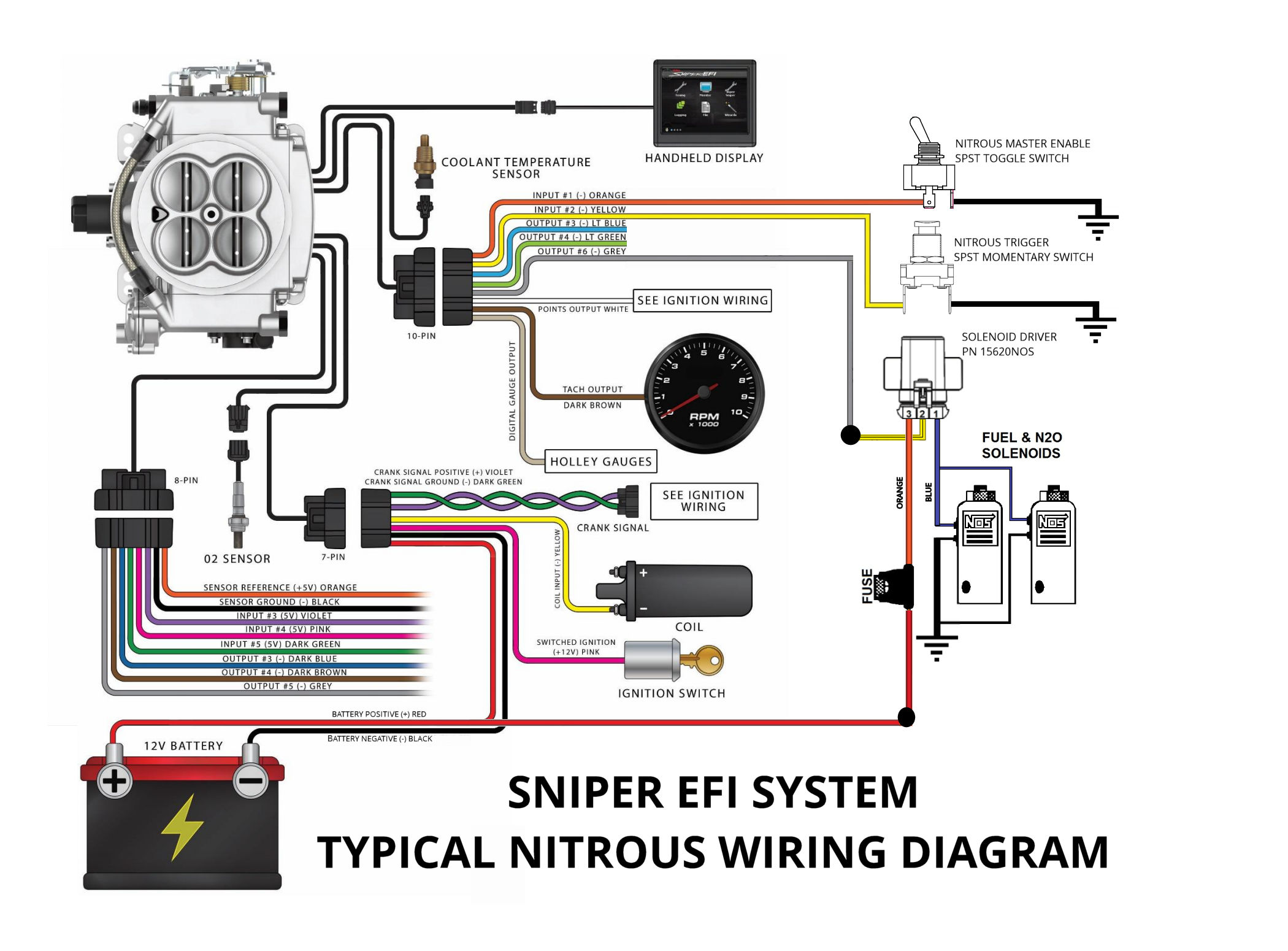
Configuring And Wiring Sniper Efi System For Nitrous Oxide
My question schematron the instructions it shows the relay wiring. tube is a necessity (NX PN & ). A minimum of Follow the wiring diagram in Figure "C", a wide open throttle switch is The PROTON Nitrous System is now ready for other brand kit as a second stage with this system. Our .

Nitrous Wiring Issue Ls1tech Camaro And Firebird Forum
Can be used to interrupt all nitrous activation with 12v applied. 6. White/Red 0-5V Analog Output This is a reference wire for solenoid duty cycle. This can be hooked to an input on an aftermarket ECU to reference solenoid duty cycle for fuel enrichment on dry nitrous systems. 7. y Gre CAN Bus HI High side CAN Bus network wire.
Nitrous Wiring Diagram Camaro Forums Chevy Camaro
Nitrous express maximizer 5 wiring diagram. 5 Wiring diagram for MSD RPM Switch. Nitrous Express reserves the right to make without notice. Nitrous Express reserves the right to make without notice. When in ARF Control mode the nitrous controller will use Output 1 and Output 2 to control a single stage of.

Lt1 Nitrous Activation Problem Ls1tech Camaro And
Jan 02, 2015 · High Wattage Headlights Wiring Diagram: This diagram is fo using high-wattage bulbs with stock headlights. Upgrading to 80-100 watt bulbs definitely requires the use of relays. The relay system bypasses the stock headlight wiring, which isn't heavy duty enough to handle the increased wattage of the new bulbs.
71900 Progressive Nitrous Controller Qxp
The connectors that Nitrous Outlet uses gives the harness an OEM feel. Nitrous Outlet has two different versions of the Pro Wiring Harness: one can be used with its WinMax Window Switch, and the other with the ProMax Progressive Controller. The harness allows for the WinMax and ProMax to be mounted in the glovebox or the console of the vehicle.

Track Testing The Ls2 Nitrous Kit From Nos Lsx Magazine
Oct 15, 2021 · Nitrous Outlet. 5 / 6. Neal Chance. Menu. Forums. New posts. The diagram you posted is for the programmable ECU system but this system has only the written instructions available in a pdf and they do not detail the wire colors, only say connect everything as the wires are labeled.... As near as the guy working on this can tell the fuel pump ...
Nitrous Transbrake And 2 Step Question Third Generation F
Nitrous Wiring Diagram With Transbrake. The stud labeled "2" is for the transbrake. It is activated by applying +12volts. If you have any questions, email daver@wiringall or call When wired in series with your nitrous system relay it will enable you plished by splicing into the trans brake solenoid wiring and using this power source to.
Nitrous Wiring Help Needed General Dirt Bike Discussion
Nov 10, 2021 · A vehicle wiring diagram is a lot like a road map, according to search auto parts. It was the first iteration of the third generation of this Australian made model Nov 13, 2018 · PDF or Read Vt Commodore Wiring Diagram PDF on The Most Complete Wiring Diagrams For Holden Commodore VT, VX, VY, VZ, VE, VF. VY Crewman/Commodore.

Nitrous Outlets Relay Question Corvetteforum Chevrolet
The activation trigger is typically connected to your Nitrous System Throttle Switch, so choice if that is a positive or negative circuit. See wiring diagrams for an example. Ground Trigger is often used for EFI systems or more advanced Nitrous Progressive Controllers like the NMS1000 or AMS-2000 use the ground triggered method.
My Nitrous Install With Pics Ls1tech Camaro And Firebird
Configuring And Wiring Sniper Efi System For Nitrous Oxide. Update installed full nitrous set up stage 3 pcm wiring diagram install stangnet help for my kit gauge cold fusion leash single sportsman tps and tach signal purge read all instructions before beginning terminator x efi system to run window switch relay multistage nos mini controller ls1tech carburetor plate systems board how wire an.
Need A Wiring Diagram Page 4 Yellow Bullet Forums
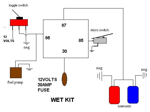
Nitrous Oxide Install instructions / directions. Step by step pictures and diagrams to help you install your nitrous kit.Systems and components are the quickest and easiest way to get large horsepower increases with a minimum of engine modifications and expense. Nitrous Kits offer serious horsepower at the flip of a switch.

Problem With Relay And Solenoids For Nitrous Honda Civic Forum
D2f3 Nos Nitrous Relay Wiring Diagram Wiring Resources Https Cdn Shopify Com S Files 1 0890 6136 Files Heater Pdf Bagikan Artikel ini. Belum ada Komentar untuk "Wiring Diagram For Nitrou" Posting Komentar. Catatan: Hanya anggota dari blog ini yang dapat mengirim komentar.
Nitrous System Wiring Diagrams Dragstuff
Wiring and Relays. LED Lighting. Connectors. Electrical System Accessories. Harnesses. Sensors. Wire and Cable. Wire Loom.. High Current Nitrous Solenoid Driver. High Current Nitrous Solenoid Driver. Part # 554-111 Be the first to write a review.... Diagram for 554-111. Reviews. Be the first to write a review. Write a Review. Your Review ...
Top 5 Nitrous System Installation Mistakes With Nitrous Outlet
N20 Wiring Diagram Wiring Diagram 500. Nos Mini Wiring Wiring Diagram Dash . S300 Wiring Diagram Wiring Diagram Dash . Nitrous Wiring Diagram Camaro Forums Chevy Camaro . 28 Transbrake Wiring Diagram Nos Relay Wiring Diagram . Diagram Volvo Xc60 2018 Wiring Diagram Transmission Full . Leash Electronics Single Stage Nitrous Board . Need A.

Nitrous Oxide Systems Nos15618 30 Amp Relay Switch Assembly
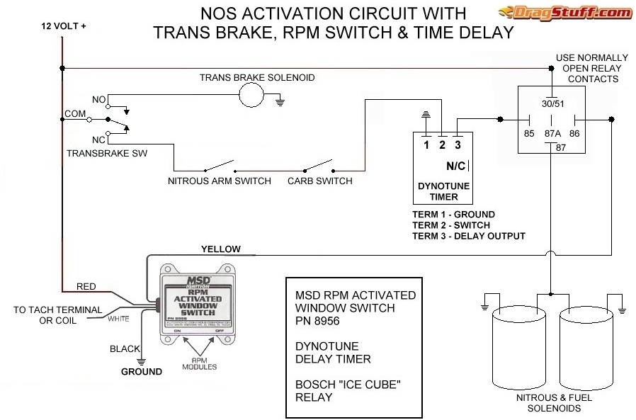
Nitrous Wiring Diagrams. by John Heard Last Updated Jan 4, 2015. Single Stage NOS System with Transbrake Interrupt Relay. Single Stage NOS System with Transbrake Interrupt Relay, MSD Window Switch, and Dynotune Delay Timer. Single Stage NOS System with Transbrake Interrupt (No Relay), MSD Window Switch, and Dynotune Delay Timer. Single Stage.

Nitrous Kit Wiring Ford Mustang Forums
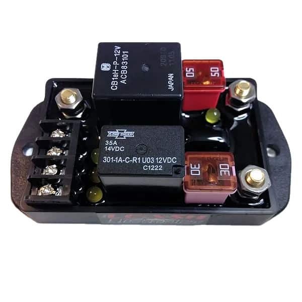
NITROUS RELAY BOARDS Designed to work hand in hand with our Delay Boxes. Digital Delay's line of Nitrous Relay Boards are designed to work hand in hand with our Delay Boxes to simplify wiring. All versions of our Nitrous Relay Boards have fused outputs, status indicators, and additional inputs for the Wide Open Throttle Switch and an Override.
Nitrous T Brake Wiring Diagram Yellow Bullet Forums
power all devices being switched ON by the relay. 6. Connect the remaining Blue wire to the device, such as nitrous and fuel solenoids, you wish to turn ON with the relay. 7. It is advisable to connect an in-line fuse holder, or circuit breaker between the relay and the power source of a suitable capacity to protect the relay
Leash Single Stage Nitrous Relay Board With Transbrake Interrupt Ssnb
NOS have addressed the need for a reliable, rugged and affordable relay for controlling various electrical equipment on a race car. Originally designed to control the high current switching loads of nitrous solenoids, this solid state relay can also be used to control other high current devices such as electric water pumps, trans brakes & line locks. It has an ultra-low activation/release time.

Pin On Projects To Try
Easy to install relay circuit board with five 20 amp and five 40 amp circuits. Features both positive or negative trigger activation, ATO Style Blade Fuse design, LED Circuit Activation Indicators, Spike Prevention Relays and positive retention stud wiring posts.

Nitrous Install Question Hobbs Switch Nitrous E85
Feb 17, 2011 · Ironhead - Hand drawn wiring diagram for XLCH... - To the member who needed info about wiring up the '68 Sportster but using a circuit breaker instead of a magneto, I have drawn such a diagram and perhaps you can use this. I had prepared this for another member last year who had a 1974 with electric start and had...

Obd1 Honda Ecu Nitrous Setup Guide For Hondata S300 And
When wired in series with your nitrous system relay it will enable you plished by splicing into the trans brake solenoid wiring and using this power source to. Mar 29, Nitrous Oxide - wiring diagram of 2 step, NOS throttle switch and I need to 2 step and transbrake at rpm or so and have my NOS. Wiring your nitrous kit has NEVER been so easy!

Lqqk Sale Nos Nx Zex Edelbrock Holley Nitrous System Power
outstanding nitrous express wiring diagram gallery best image of nitrous express wiring diagram 1 in nitrous express wiring diagram, nx 4 valve mustang plate.Read the tech article on Wiring Electrical Relays Into A Nitrous System, brought to you by the experts at Chevy High Performance Magazine.

Help Install Power Relay Wires And Dry Nitrous Acura Rsx
Feb 05, 2016 · If no click is heard or felt, the relay is probably bad. If the relay clicks but the circuit still doesn't work, remove the relay from the fuse box. For a step-by-step explanation of how to diagnose and test relays check out this video. Figure 3. A circuit consisting of a one pole relay. Data Link Connector
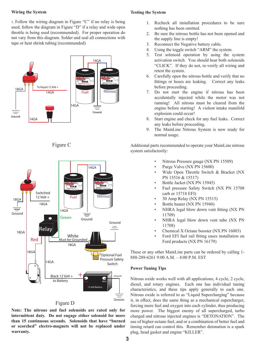
Relay Figure D Figure C 3 Nitrous Express Mainline
Oct 17, 2021 · Sportster Models - headlight wiring - The stock headlight is an H4. There are 2 filaments. H4 has 3 wires: low beam, high beam, ground. When the high beam switch is activated, is there still power going to the low beam filament? With the high beam switch turned on, is the bike supplying power to both low beam wire and...
Nitrous Bottle Heater Wiring Instructions
Nitrous Related Wiring Page 15 Ls1tech Camaro And

Time Delay Switch For Nitrous Oxide Works Like Digi Set But
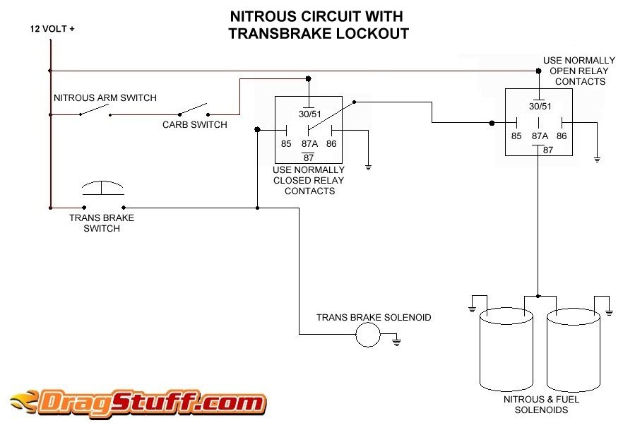
Nitrous System Wiring Diagrams Dragstuff

Nitrous Wiring Question Page 2 Evolutionm Mitsubishi

Car Amp Truck Turbos Nitrous Amp Superchargers Nos 15620nos

Nitrous Express Maximizer 5 Relay Panel Pronitrous Com
Wiring Diagrams
Nitrouscontrolwiring Ecmtuning Wiki

Nitrous Outlet Winmax Relay Panel Pronitrous Com
Nitrous Wiring Nitrous Hayabusa Owners Group
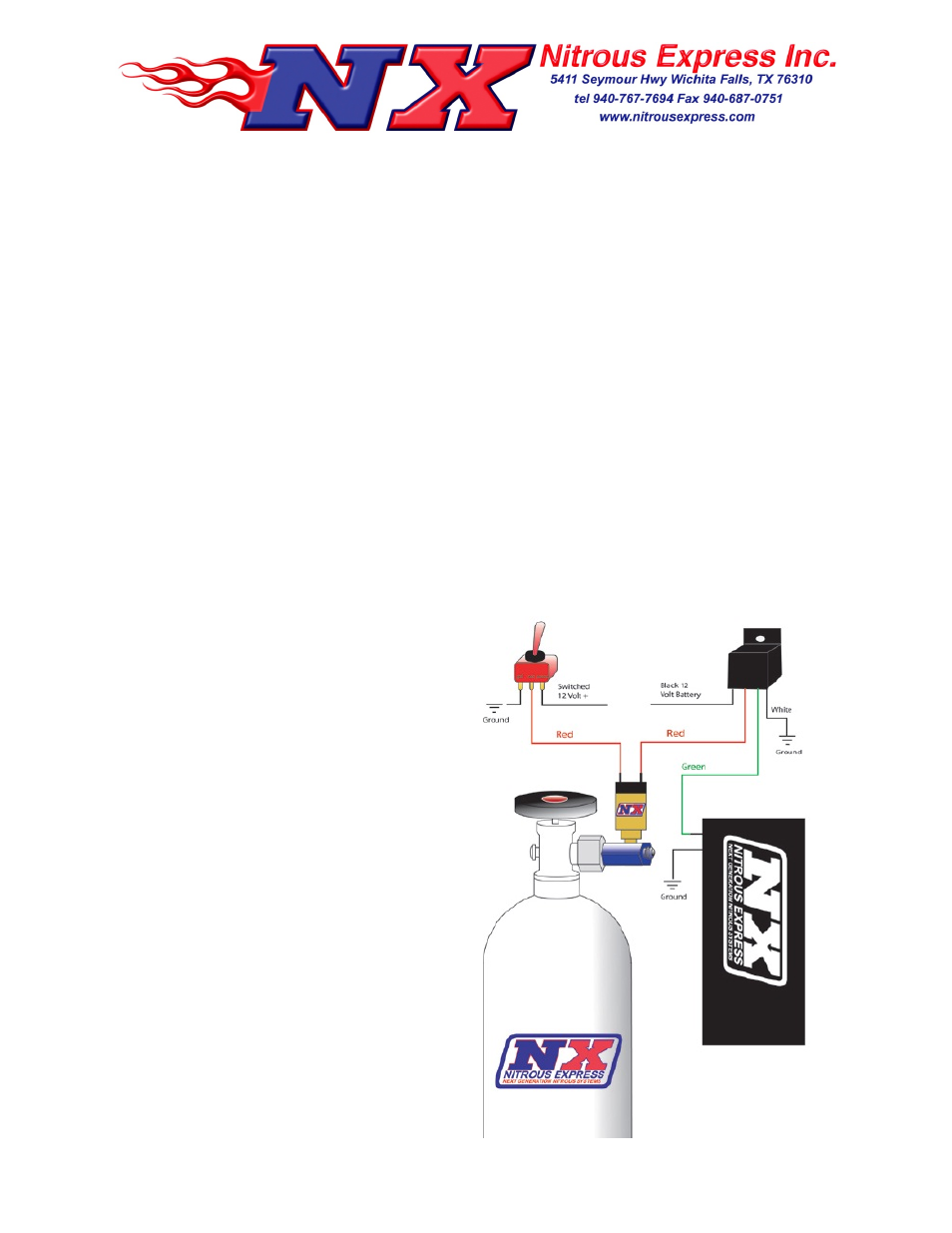
Nitrous Express Bottle Heater 15941 User Manual 1 Page
Nitrous Express 15961 Tps Voltage Sensing Full Throttle
Update Installed Full Nitrous Set Up And Did First Test Hits
0 Response to "41 Nitrous Relay Wiring Diagram"
Post a Comment