37 Sewage Treatment Plant Process Flow Diagram
The preliminary treatment is a physical process of using large bars or screens to remove large pieces of garbage from the incoming wastewater (influent). By removing large trash in this initial step, this phase protects the main sewage system and equipment from potential damage. Contains sequence of unit operations of WTP, Preliminary, Primary, Secondary and Tertiary Treatments
Typical Flow Diagram of Sewage Treatment Plant FINE SCREENIN G GRIT REMOVAL RAW GRIT SEWAGE INLET CHAMBER RAW SEWAGE PUMPING COARSE SCREENIN G. 10 ppm, TN < 10 ppm, TP < 2 ppm in a single stage of treatment using Batch process. • Bio-nutrient removal (BNR) : N & P removal • Secondary clarifier not required, less foot print area

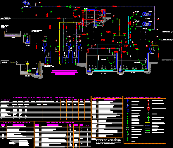
Sewage treatment plant process flow diagram
Toyono water treatment plants using the Ozonation-Biological Activated Carbon process were built[10]. Figure 1. Flow diagram of the water plant in Rouen La Chapella By now, BAC process has become the major process in advanced water treatment, which is commonly used in developed countries such as America, Japan, Holland, Switzerland, etc[1]. Effluent treatment plant process flow diagram-Effluent treatment block is that part of industry which never take part in production but help to treat the affluent. The main role of ETP is purify the effluent which is come from production plant . Typical Wastewater Treatment Plant Flow Diagram. Related Papers. CSE364 Handout doc. By Eric W. Course Code : 17CE5126 L-T-P structure : 3-0-2 Course Credits : 4 Course Coordinator Course Instructors. By Vijayan G Iyer. XIII-Water-C-Sewage Treatment-1 SEWAGE TREATMENT. By nasr rageh and sangar mohammad.
Sewage treatment plant process flow diagram. Pin By Nonhlanhla Radebe On W Ww Treatment Water Treatment Plant Water Treatment Wastewater Treatment Plant Vendor Payment Process Chart Process Chart Process Flow Chart Process Flow Water Cycle Diagram Water Cycle Diagram Cycle Drawing Easy Drawings A Conceptual Diagram Of The Hydrologic Cycle After Wisler And Brater 1959 Reproduced By Permission Of John Wiley […] Typical Wastewater Treatment Plant Flow Diagram. Related Papers. CSE364 Handout doc. By Eric W. Course Code : 17CE5126 L-T-P structure : 3-0-2 Course Credits : 4 Course Coordinator Course Instructors. By Vijayan G Iyer. XIII-Water-C-Sewage Treatment-1 SEWAGE TREATMENT. By nasr rageh and sangar mohammad. WASTEWATER TREATMENT PLANT FLOW DIAGRAM (Not to Scale) Main Pump Station PPS SPS Digester Building 8 Effluent Pump Station (CHLORINE) 19th St. Bldg. N 1 2 3 Influent To Allegheny River Recycle Sludge Waste Sludge Digested Sludge Supernatant 9 Preliminary Treatment (Main Pump Station) 1 Barscreens 2 Grit Chambers Primary Treatment (Primary Pump. A conventional sewage treatment plant has the requisite operating units arranged one after another for treatment and final disposal of sewage. The flow chart of a conventional sewage treatment plant is depicted in Fig. 57.18.
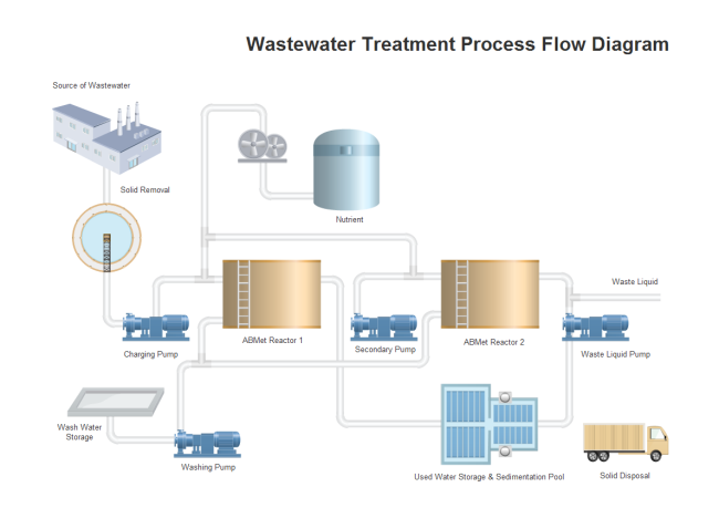
Wastewater Management Wastewater Treatment is one of the most important services a municipality may provide and one of the least visible. This chapter provides an overview of the process of wastewater treatment and provides information appropriate for municipal leaders, the general public and operators. Effluent Treatment Plant (ETP) - Process Flow Diagram (Chart 2) Housekeeping. Polymer Mixing. To assist in creating a safe & healthy workplace. Water and Sludge Separation. Sludge send to Filter Press. To aware for safe and healthy environment. Water comes from Secondary Clarifier & Sludge Thickening Clarifier. Wastewater Treatment PFD Template This PFD example is created using Edraw vector drawing software enhanced with PID solution. It shows the main process of waste water treatment visually. Here is a picture gallery about wastewater treatment plant schematic diagram complete with the description of the image, please find the image you need. Flow diagram showing the process of wastewater treatment plant which consists of HF-UF filters (hollow fiber) and SW-UF (spiral wound), activated carbon and RO filters. Sampling locations are.
Text in this Example: Drinking Water Treatment Sedimentation The heavy particles (floc) settle to the bottom and the clear water moves to filtration. Storage Water is placed in a closed tank or reservoir for disinfection to take place. The water then flows through pipes to homes and businesses in the community. Flocculation & Clarification Tank Lake, Reservoir or River Coagulation Filtration. A Process Flow Chart is a type of flowchart which is mostly used in industrial, chemical and process engineering for illustrating high-level processes, major plant processes and not shows minor details. ConceptDraw DIAGRAM diagramming and vector drawing software extended with Flowcharts Solution from the "Diagrams" Area of ConceptDraw Solution Park is the best way to create Process Flow Chart. A General Wastewater Treatment Plant Flow Diagram is included at the end of this chapter (Exhibit 4-1). The inspector should conduct an examination of process treatment units, sampling and flow monitoring equipment, outfalls, and the receiving stream , particularly focusing on areas of the Sewage sludge is obtained from wastewater treatment in sewage treatment plants. The sludge consists of two basic forms, sludge and secondary sludge, also known as activated sludge in the case of.
plants. Sewers collect the wastewater from homes, businesses, and many industries, and deliver it to plants for treatment. Most treatment plants were built to clean wastewater for discharge into streams or other receiving waters, or for reuse. Years ago, when sewage was dumped into waterways, a natural process of purification began.
The process flow for a typical wastewater treatment plant (WWTP) is shown in Figure 1. The solid red arrows indicate the process flow of the wastewater treatment process and the orange dotted.
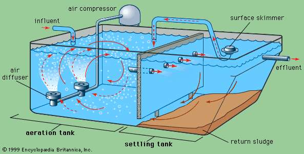
This process is a fundamental suspended growth process, accounts for most of the biological purification in sewage treatment plant because of its less working area than the trickling filter process. The basic principle of this operation is the microbial growth in an aerated system containing bio-degradable organic food.
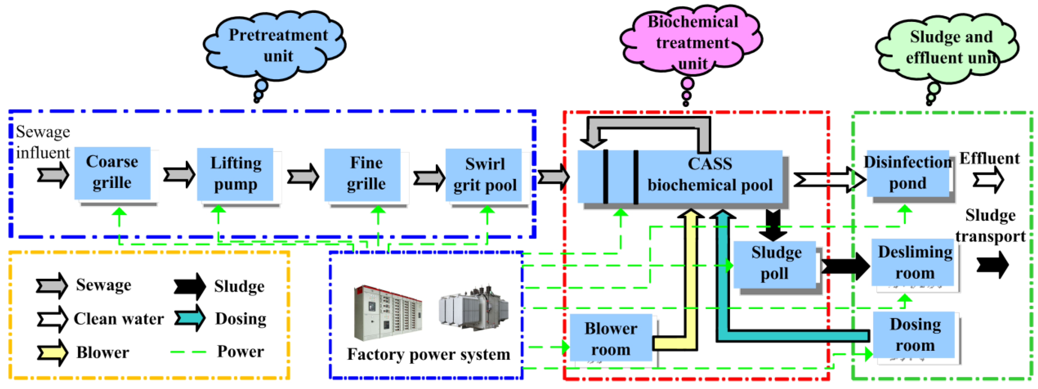
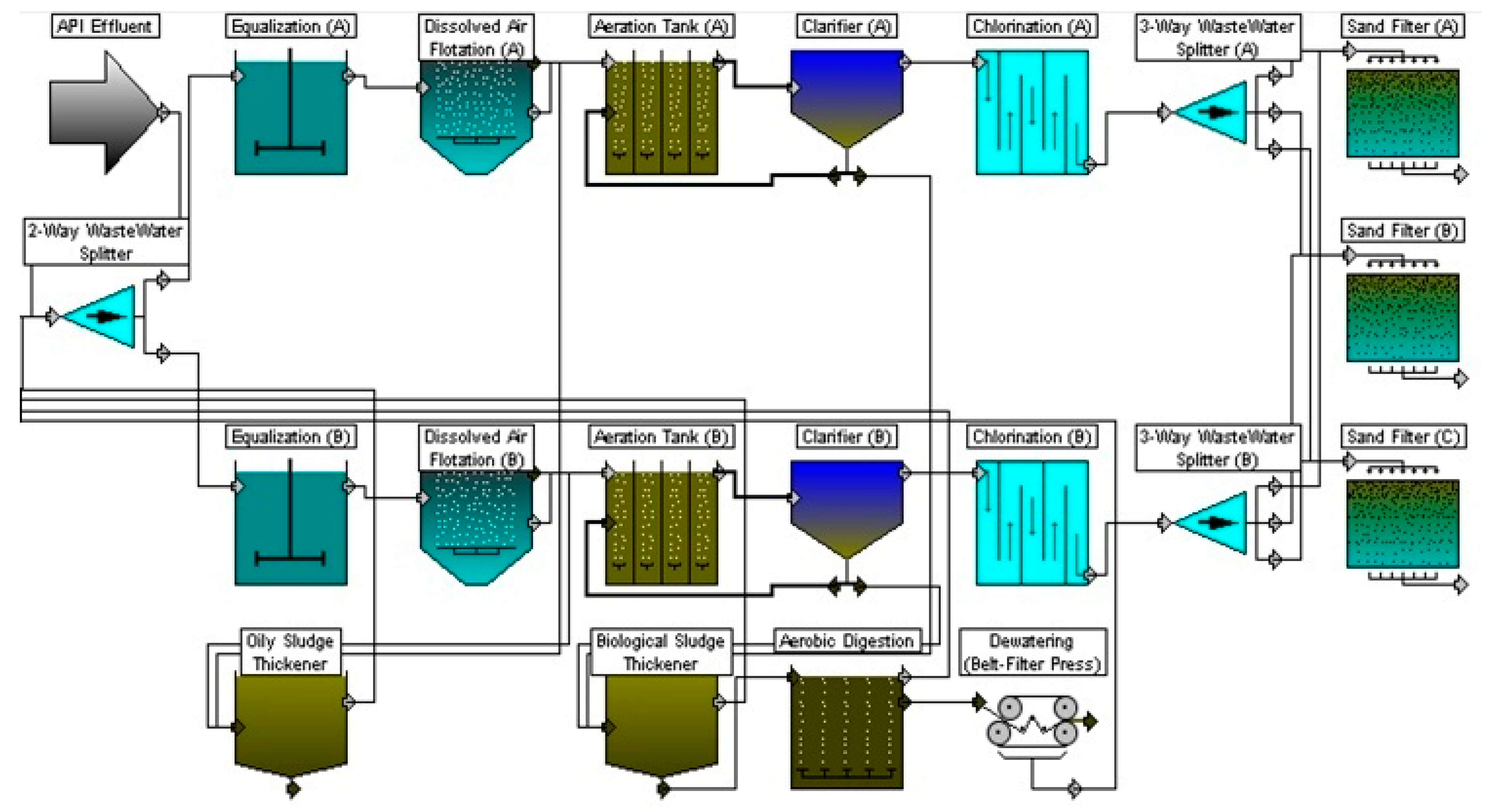
The process flow sheet or flow diagram is a graphical representation of the sequence in which various unit operations and unit processes are adopted for treatment of sewage at any sewage treatment plant. The design of process flow sheet involves selection of an appropriate combination of various unit operations and unit processes to achieve a.
Wastewater, also known as raw sewage include but is not limited to water from the bathroom, toilets kitchen and other industrial wastes. Wastewater treatment is a process of removing micro-organisms, contaminants and any other pollutants from the wastewater.. Everyday wastewater from our homes, schools toilets, businesses and even factories goes down and flows into the City's sewer system.
Wastewater Treatment Plant Flow Diagram.. Please see below for our Wastewater Process Map. Additional Product Resources. Datasheets. Manuals. Software & Drivers. Locate a Sales Rep. Contact Us. We will respond to all messages within 24 hours. USA: +1 (888) 429-5538 AU: +61 (0)3 9873 4750.
Figure C-4A: Polyethylene Plant A Process Flow Diagram Product Feeds Vent Streams Recycle Feeds Flare Feeds Fuel Burning Equipment PM Pollution Control Devices POLYMERIZATION PA-PE-202 PURGING AND VENT. Wastewater Treatment Plant. SU-EG-101 . Cracker Plant EG - 2800 kW . SU-EG-102 SU. PE Plant A EG - 2800 kW . SU-EG-103 . PE Plant C EG ...
WASTEWATER TREATMENT PROCESS Wastewater Treatment Total water treatment system, employed to treat the waste/effluent water from industry. ( Image: courtesy of wikipedia) Pre-Treatment Removal of insoluble particles from reaching treatment zone, which may hinder treatment operation. 1) Grit removal, 2) flow equalisation, 3) Fat and grease removal
Since its half-life in biological treatment is around 25 days, it can be used as an efficiency indicator of wastewater treatment plant for the removal of hydrophobic emerging contaminants.
Toyono water treatment plants using the Ozonation-Biological Activated Carbon process were built[10]. Figure 1. Flow diagram of the water plant in Rouen La Chapella By now, BAC process has become the major process in advanced water treatment, which is commonly used in developed countries such as America, Japan, Holland, Switzerland, etc[1].
Treatment Systems For Intensive Department Of Environment And Science. Flow Diagram Of Wastewater Treatment Plant Picture Courtesy Hpcidbc Scientific. A schematic of typical wastewater treatment plant scientific diagram representation waste water and pilot scale indicating the sampling amol s sewage flow 2 process b points. Wiring.
About Press Copyright Contact us Creators Advertise Developers Terms Privacy Policy & Safety How YouTube works Test new features Press Copyright Contact us Creators.
Sewage Treatment Plant, [Hindi/English] MBBR STP working Process Flow Diagram, Netsol Water Manufacturer, ConsultantWHAT IS MBBR WASTEWATER TREATMENT?Having.
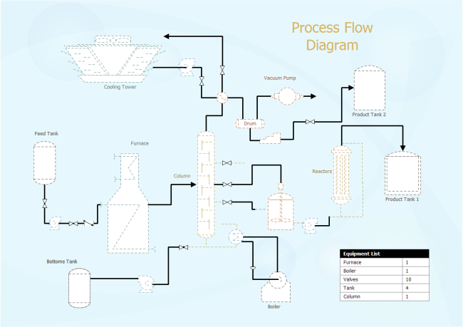
Process flow diagrams (PFDs) are used in chemical and process engineering. These diagrams show the flow of chemicals and the equipment involved in the process. Generally, a Process Flow Diagram shows only the major equipment and doesn't show details. PFDs are used for visitor information and new employee training.
Wastewater (liquid waste) from flushing the toilet, bathing, washing sinks, and general cleaning goes down the drain and into a pipe, which joins a larger sewer pipe under the road. The sewer pipe goes on to connect to a different sewer pipe that leads to the treatment center. An illustration of a basic sewage treatment plant. STAGE ONE: SCREENING
Effluent treatment plant process flow diagram-Effluent treatment block is that part of industry which never take part in production but help to treat the affluent. The main role of ETP is purify the effluent which is come from production plant .
Sewage treatment plant process includes sewage treatment on primary, Secondary or biological and tertiary treatment process to improve quality of wastewater for recycle. With increasing infrastructural development and water usage for various purposes such as domestic and commercial, there is generation of waste water.












0 Response to "37 Sewage Treatment Plant Process Flow Diagram"
Post a Comment