38 Transfer Function Block Diagram
Consider the following transfer function. Draw a block diagram for the transfer function G (s) Obtain a representation in state variables from the block diagram of the previous section. Determine if the system is controllable and observable. Design a feedback of estimated states such that the closed-loop system has a settling time of 1 second. How to draw block diagram from given transfer function in state space analysis,Transfer function to block diagram conversion,Full Series-Semiconductor Device...
As a block diagram we can represent the system by F (s) W(s) X (s) Fig. 1. Block diagram for a system with transfer function W(s). Sometimes we write the formula for the transfer function in the box representing the system. For the above example this would look like F (s) 1 ms2 + bs+ k X (s) Fig. 2. Block diagram giving the formula for the.
Transfer function block diagram
Transcribed image text: Using block diagram reduction, determine the transfer function T(s) = C(s)/ R(s) for the following system. Describe the steps you are taking and clearly state your final result for r(s). Transfer Functions The transfer function of a linear system is the ratio of We need ways to reduce a complicated block diagram to a simpler form, for example, Chapter Two Transfer Function Approach Block diagram algebra is introduced in Section 2.3 as Example 2.3: The transfer function for the linearized system from BLOCK DIAGRAM ALGEBRA AND TRANSFER FUNCTIONS OF SYSTEMS [CHAP. 7 We do not apply Step 3 at this time, but go directly to Step 4, moving takeoffpoint I b'eyond block G2 + G3: i [.1 .2 C G2 + G3 We may now rearrange summing points 1 and 2 and combine the cascade blocks in the forward loop using.
Transfer function block diagram. Transfer function block diagram. 1. Find the difference equation and draw the simulation diagram. 4. Find transfer function from root locus and step response diagram? 3. Poles and zeros of a transfer function. 0. Block diagram for a complex impulse response. 0. Inverse Fourier of Two-Pole Transfer Function. Example 14: Antenna Control: Designing a closed-loop response The system shown below is the block diagram of an antenna azimuth control system. Determine the transfer function and SFG for the system. Using block reduction techniques 1. Push input potentiometer to the right past the summing point 2. Combine cascade block 3. Eliminate feedback loop Transcribed image text: Using block diagram reduction, determine the transfer function T(s) = C(s)/ R(s) for the following system. Describe the steps you are taking and clearly state your final result for r(s). Rules for Block Diagram Reduction. So, one by one we will discuss the various rules that can be applied for simplifying a complex block diagram. For serially connected blocks. When blocks are connected in series then the overall transfer function of all the blocks is the multiplication of the transfer function of each separate block in the.
Transfer function: It is defined as the ratio of the Laplace transform of the output variable to the Laplace transform of the input variable, with all zero initial conditions. Block diagram: It is used to represent all types of systems. Example Problem on how to derive closed loop transfer function from Block Diagram Figure 4: Block diagram of a closed-loop system with a feedback element. BLOCK DIAGRAM SIMPLIFICATIONS Figure 5: Cascade (Series) Connections. Consider a system whose closed-loop transfer function is H(s) = K s(s2 +s+1)(s+2)+K. (18) The characteristic equation is s4 +3s3 +3s2 +2s4 +K = 0. (19) The Routh array is s4 1 3 K s3 3 2 0 s2 7/3 K ... block diagram shown in Figure 3-44. Figure 3-46 Block diagram of a system. Solution. The block diagram of Figure 3-44 can be modified to that shown in Figure 3-45(a). Eliminating the minor feedforward path, we obtain Figure 3-45(b), which can be simplified to that shown in Figure 3--5(c).The transfer function C(s)/R(s) is thus given by
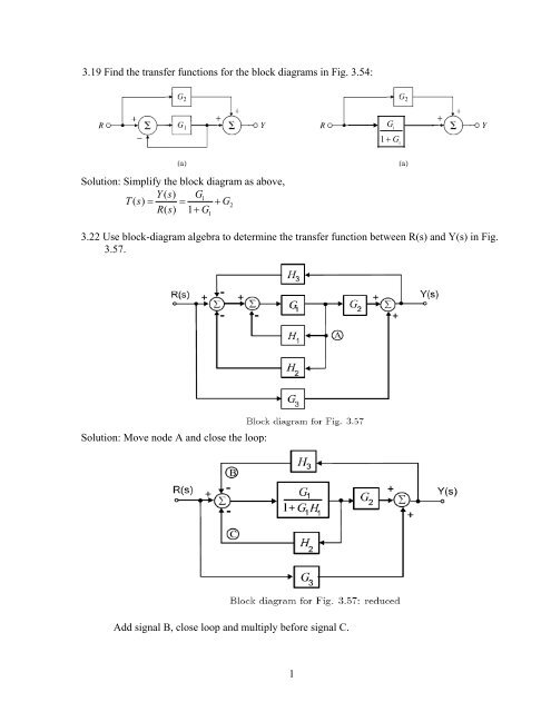
Apr 15, 2015 · Block diagram Examples 1. Control System Engineering Kuntumal Sagar M. B.TECH (E.E) UID-U41000000484 Email: skuntmal@yahoo TOPIC BLOCK DIAGRAM EXAMPLES 2. Example 9 Find the transfer function of the following block diagrams 2G 3G1G 4G 1H 2H )(sY)(sR 3. 1. Moving pickoff point A ahead of block 2G 2. •A Block Diagram is a shorthand pictorial representation of the cause-and-effect relationship of a system.. •The control ratio is the closed loop transfer function of the system. •The denominator of closed loop transfer function determines the characteristic equation of the system. •Which is usually determined as: ( ) ( ) ( ) ( ) ( ) Draw block diagram from the following equations. Q Motor position transfer function with speed changer. Note: multiplication by s. 10/28/2015 12 DC MOTOR TRANSFER FUNCTION EXAMPLE 23 x Example 14-2: A permanent magnet dc motor has the following specifications. Maximum speed = 500 rad/sec 3.19 Find the transfer functions for the block diagrams in Fig. 3.54: Solution: Simplify the block diagram as above, 1 2 1 () 1 Ys G Ts G Rs G == + + 3.22 Use block-diagram algebra to determine the transfer function between R(s) and Y(s) in Fig. 3.57. Solution: Move node A and close the loop: Add signal B, close loop and multiply before signal.
.png?revision=1)
11 5 Block Diagrams And Transfer Functions Of Feedback
Transfer Functions The transfer function of a linear system is the ratio of We need ways to reduce a complicated block diagram to a simpler form, for example, Chapter Two Transfer Function Approach Block diagram algebra is introduced in Section 2.3 as Example 2.3: The transfer function for the linearized system from
Transfer Functions Block Diagrams And The S Plane Springerlink
Calculate Transfer function from block diagram. Then, draw signal flow for following system and calculate transfer function from signal flow. Design block diagram and signal flow for following circuit. (Output is the R2 voltage) 005_jkbpqpk-erphxiiw.jpg 005_v6fpqpk-techiigl.jpg. Nov 28, 2021.
Block Diagram Reduction Shortcut Rules In Control System
In engineering, a transfer function (also known as system function or network function) of a system, sub-system, or component is a mathematical function which theoretically models the system's output for each possible input. They are widely used in electronics and control systems.In some simple cases, this function is a two-dimensional graph of an independent scalar input versus the dependent.
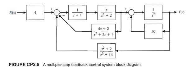
Solved Consider The Block Diagram In Figure Cp2 6 A Use
Transfer Functions. A transfer function is a mathematical formulation that relates the output variable of a device to the input variable. For linear devices, the transfer function is independent of the input quantity and solely dependent on the parameters of the device together with any operations of time, such as differentiation and integration that it may possess.

1 Write A Matlab Program For The Following Block Diagram A
Step 1 − Find the transfer function of block diagram by considering one input at a time and make the remaining inputs as zero. Step 2 − Repeat step 1 for remaining inputs. Step 3 − Get the overall transfer function by adding all those transfer functions. The block diagram reduction process takes more time for complicated systems. Because.
Transfer Functions In Block Diagrams Dynamics And Control
Transfer Functions in Block Diagrams One source of transfer functions is from Balance Equations that relate inputs and outputs. Transfer functions are compact representations of dynamic systems and the differential equations become algebraic expressions that can be manipulated or combined with other expressions.

The Transfer Function C S R S Of The System Whose
G(s) – Forward path transfer function. H(s) – Feed back path transfer function. Block diagram reduction technique . Because of their simplicity and versatility, block diagrams are often used by control engineers to describe all types of systems. A block diagram can be used simply to represent the composition and interconnection of a system.

Transfer Function Block Diagram For Lowfrequency Oscillations
K. Webb MAE 4421 3 Block Diagrams In the introductory section we saw examples of block diagrams to represent systems, e.g.: Block diagrams consist of Blocks-these represent subsystems - typically modeled by, and labeled with, a transfer function Signals- inputs and outputs of blocks -signal direction indicated by
.png?revision=1)
11 5 Block Diagrams And Transfer Functions Of Feedback
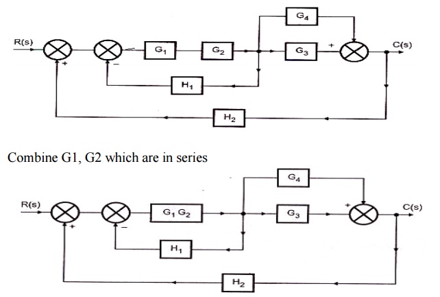
160 BLOCK DIAGRAM ALGEBRA AND TRANSFER FUNCTIONS OF SYSTEMS [CHAP. 7 Let the - 1 block be absorbed into the summing point: Step 4c Step 5: By Equation (7.3), the output C, due to input U is C, = [G2/(1 + G1G2)]U. The total output is C=C,+C,= [ ~ 1 +G2G2] [ A] [ A] IGIR + 7.8 REDUCTION OF COMPLICATED BLOCK DIAGRAMS The block diagram of a practical feedback control system is often quite complicated.
H1 Align Center Gt Enotes Mechatronics And Controls Lt H1 Gt
2. Block diagram models The block diagram is a diagrammatic means to represent the cause-and-effect relationship of system variables. It consists of unidirectional, operational blocks that represent the transfer function of the variables of interests. Fig.4: Components of a block diagram for a linear, time-invariant system

The Transfer Function C R Of The Block Diagram Given Below
BLOCK DIAGRAM ALGEBRA AND TRANSFER FUNCTIONS OF SYSTEMS [CHAP. 7 We do not apply Step 3 at this time, but go directly to Step 4, moving takeoffpoint I b'eyond block G2 + G3: i [.1 .2 C G2 + G3 We may now rearrange summing points 1 and 2 and combine the cascade blocks in the forward loop using.
Block Diagram Reduction Techniques Transfer Function
5. Block Diagram To Transfer Function Reduce the system shown below to a single transfer function, T(s) = C(s)=R(s). Solution: Push G 2(s) to the left past the summing junction. Collapse the summing junctions and add the parallel transfer functions. Rev. 1.0, 02/23/2014 4 of 9

The Block Diagram Of A Control System Is Shown Below Using
4.4 Block Diagrams Using the Laplace transform linearity and convolution properties we can easily extend the concept of the transfer function to configurations of several connected linear systems. In that way we will find the equivalent transfer functions for cascade and parallel connections of systems, introduce the feedback (closed-loop)
Transfer Function Amp Block Diagram Computer Amp Electronics
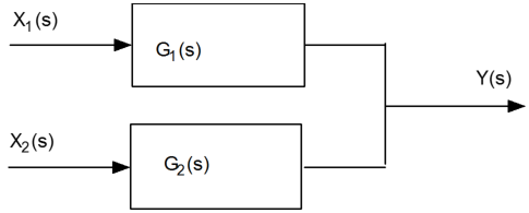
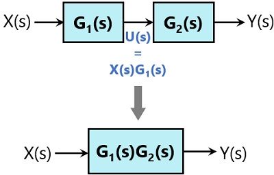
The transfer function of this single block is the product of the transfer functions of those two blocks. The equivalent block diagram is shown below. Similarly, you can represent series connection of 'n' blocks with a single block. The transfer function of this single block is the product of the transfer functions of all those 'n' blocks.
1 3 19 Find The Transfer Functions For The Block Diagrams In
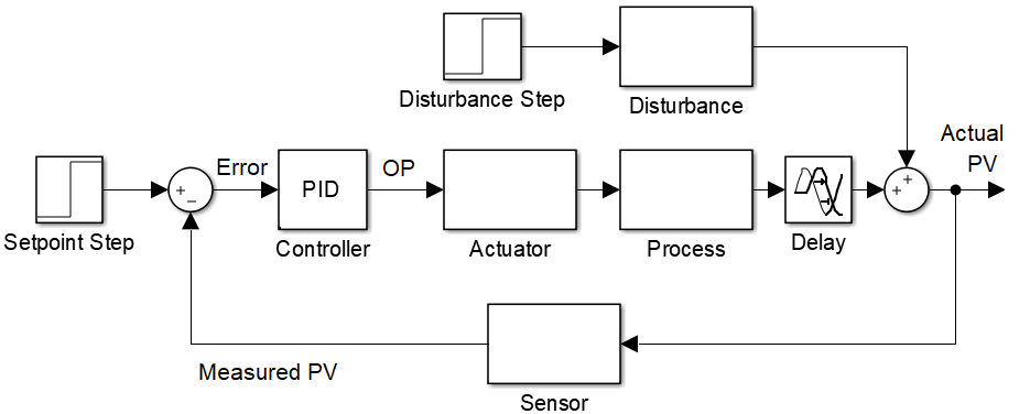
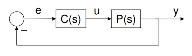
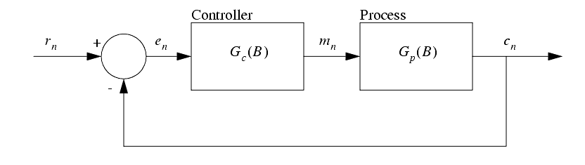
Block Diagram of Closed Loop Control System. In a closed-loop control system, a fraction of output is fed-back and added to the system's input. If H (s) is the transfer function of the feedback path, then the transfer function of the feedback signal will be B (s) = C (s)H (s). At the summing point, the input signal R (s) will be added to B (s.

Control Theory What Is Block Diagram For These Transfer
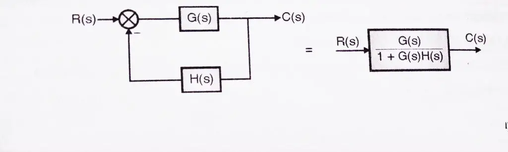
An example of a closed-loop transfer function is shown below: The summing node and the G(s) and H(s) blocks can all be combined into one block, which would have the following transfer function: () = + () is called feedforward transfer function, () is called feedback transfer function.

Transfer Function Block Diagram Of Dc Motor Download
K. Webb ESE 499 3 Block Diagrams In the introductory section we saw examples of block diagrams to represent systems, e.g.: Block diagrams consist of Blocks - these represent subsystems - typically modeled by, and labeled with, a transfer function Signals - inputs and outputs of blocks - signal direction indicated by arrows - could be voltage, velocity, force, etc.
Get Transfer Function From Block Diagram Physics Forums
When an IREF specifies input data for a function block instruction, the data in that IREF is latched for the scan of the function block routine. The IREF latches data from program-scoped and controller-scoped tags. The controller updates all IREF data at the beginning of.

Transfer Function Algebra X Engineer Org
Feb 24, 2012 · A block diagram is a visualization of the control system which uses blocks to represent the transfer function, and arrows which represent the various input and output signals. For any control system, there exists a reference input known as excitation or cause which operates through a transfer operation (i.e. the transfer function) to produce an.
Block Diagram Representation Of Control Systems
I have a block diagram that I am trying to get the transfer function for but can't seem to figure it out, I am sure that I am making it more difficult than it needs to be but still can't get it. The diagram is below and any help would be great!

Block Diagram Construction
Block diagram transfer function calculator

Converting A Transfer Function To State Space Transfer
Using these transformations, a complicated block diagram of transfer functions can be reduced to a single equivalent transfer function. The advantage of having a single transfer function is that several analysis methods can be applied in order to understand the controllability and observability of the system.
Section 1 Introduction
This block diagram can certainly be recreated in Simulink. I suggest you start with 'Transfer Function' blocks and 'Sum' blocks, to match the transfer functions and sums in the diagram. I am not sure what the 'F' blocks in your diagram refer to, but if they are simply gains, then you can use a 'Gain' block to represent each one.
Electronics Free Full Text Design And Analysis Of A Drive

Transfer Function Block Diagram Of The Avr System Download

Block Diagrams And Their Transfer Functions For The Exact

Block Diagram Of Control Systems Transfer Functions
Converting A Transfer Function To State Space Representation
Section 1 Introduction
Ppt The Block Diagram Powerpoint Presentation Free
Transfer Functions In Block Diagrams Dynamics And Control

Block Diagram Of A Transfer Functions Model Of The Control
Block Diagram Of Control Systems Transfer Functions
Block Diagram Reduction Rules With Example Electronics Coach
Block Diagrams 8 Tutorial Sheet On Closed Loop Transfer Functions And Use Of Matlab

Mathematical Models Block Diagrams

File Block Diagram For Sensitivity Transfer Function Svg
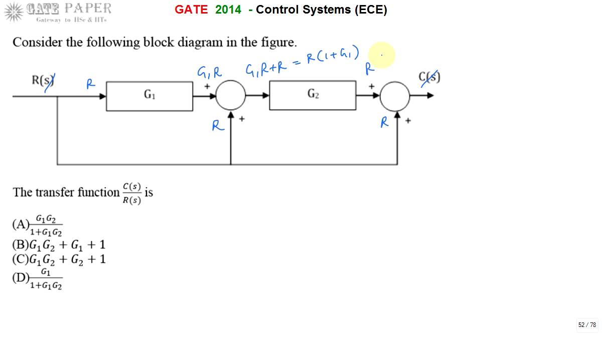
Gate 2014 Ece Transfer Function Of Given Block Diagram
0 Response to "38 Transfer Function Block Diagram"
Post a Comment