37 Mefi 4 Wiring Diagram
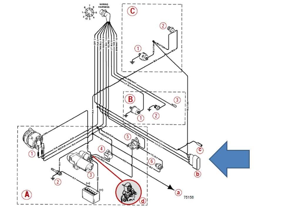
Mercruiser 7.4 Wiring Diagram. Mercruiser L Wiring, Mercruiser L Marine Engine Wiring Diagram Mercruiser L Performance Spec's, Mercruiser engine specifications including. Thunderbolt IV mounted on exhaust elbow wht/red from module to dis. wht/grn from module to dis. gray neg on coil to tac. and to module. purple. Apr 13, · Hi, I am in need of a mefi 1 mercruiser v8 wiring diagram. I have the mefi 1 with harness and the mefi burn software. truck pulling,, small 5/5. 2 IGNITION COIL WIRING CONNECTOR Pin A is B+ from MEFI System Relay Pin B is unused Pin C connects the Ignition Coil to the Ignition Module 3 HEAT SINK 4 IGNITION CONTROL MODULE MOUNTING.
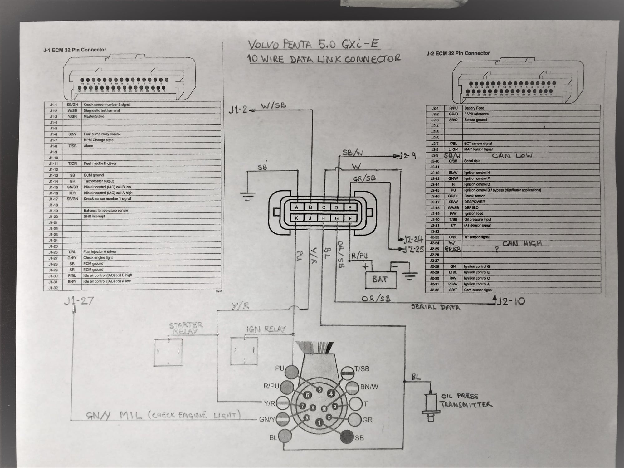
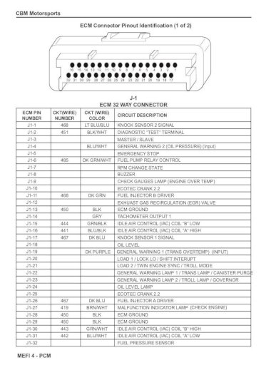
MEFI 4 - PCM ECM Connector Pinout Identifi cation (1 of 2) 16 15 14 13 12 11 10 9 8 7 6 5 4 3 2 1 32 31 30 29 28 27 26 25 24 23 22 21 20 19 18 17 J-1 ECM 32 WAY CONNECTOR ECM PIN CKT(WIRE) CKT (WIRE) CIRCUIT DESCRIPTION NUMBER NUMBER COLOR

Mefi 4 wiring diagram
Mefi 4 Wiring Harness Diagram Ls1 Further note that the confirms this is a MEFI-3 ECM by the Rinda connections documents, wiringall and the OBD2AllInOne site. Efi 3 Wire Map Sensor Wiring Diagram - MegaManual Index-- External Wiring Schematic-- External Wiring with a V Main Board-- Some Wiring Considerations General Guidelines for. Engine Control Module (ECM), wiring harness, all the necessary sensors, distributor, ignition coil, throttle body, fuel rail, and throttle cable brackets. All the gaskets and attaching hardware required for the components you need to. 6 Gasket, intake manifold lower to upper 4 12489372 7 Intake manifold bolt, upper to lower 8 12490255 8 Air... mefi 4 wiring harness diagram ls1 wiring diagram operations. Architectural wiring diagrams proceed the approximate locations and interconnections of receptacles, lighting, and permanent electrical services in a building. Interconnecting wire routes may be shown approximately, where particular receptacles or fixtures must be on a common circuit.
Mefi 4 wiring diagram. Engine Control Module (ECM), wiring harness, all the necessary sensors, distributor, ignition coil, throttle body, fuel rail, and throttle cable brackets. All the gaskets and attaching hardware required for the components you need to. 6 Gasket, intake manifold lower to upper 4 12489372 7 Intake manifold bolt, upper to lower 8 12490255 8 Air... Mefi 4 Wiring Harness Diagram Ls1 Further note that the confirms this is a MEFI-3 ECM by the Rinda connections documents, wiringall and the OBD2AllInOne site. Efi 3 Wire Map Sensor Wiring Diagram - MegaManual Index-- External Wiring Schematic-- External Wiring with a V Main Board-- Some Wiring Considerations General Guidelines for. The following diagram is a representation of the general inputs and outputs of the MEFI-4 system. Here's a basic look at how the sensors in the speed-density MEFI-4 fuel injection work. Engine load is primarily determined by sensing the current engine speed and reading the manifold pressure via the manifold absolute pressure (MAP) sensor (this. Re: Tried out new MEFI 4 b software today 10-06-06 11:10 AM - Post# 1011055 In response to monty56 I found out the scoop on the MEFI 4b wideband O2. You just hook up the O2 sensor wires 0-5 V to connector J2 pin 6 and the ground wire to J2 pin 3, of if your MEFI harness has an O2 sensor plug, the 5V wire goes to pin B and the ground to pin A in the oxygen sensor connector.
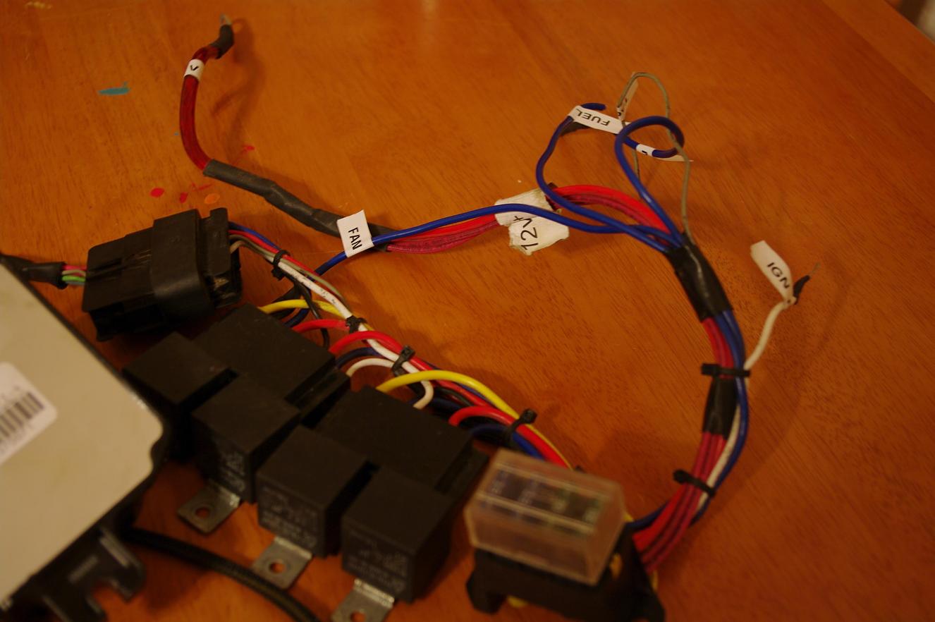
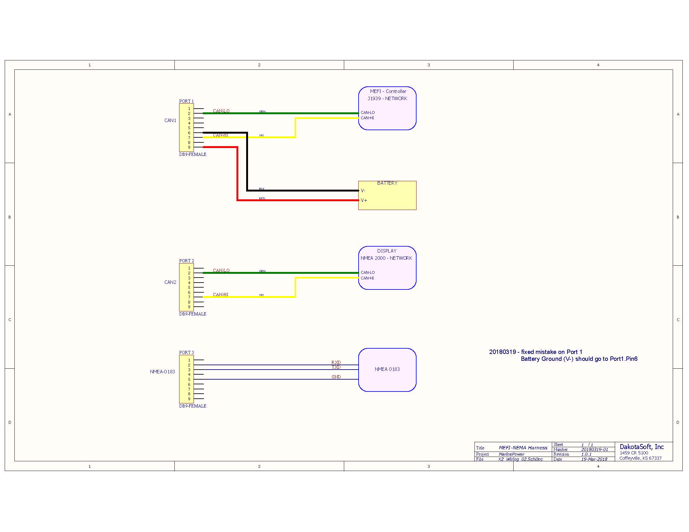
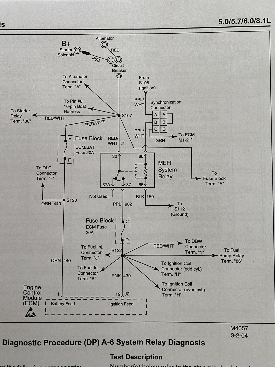
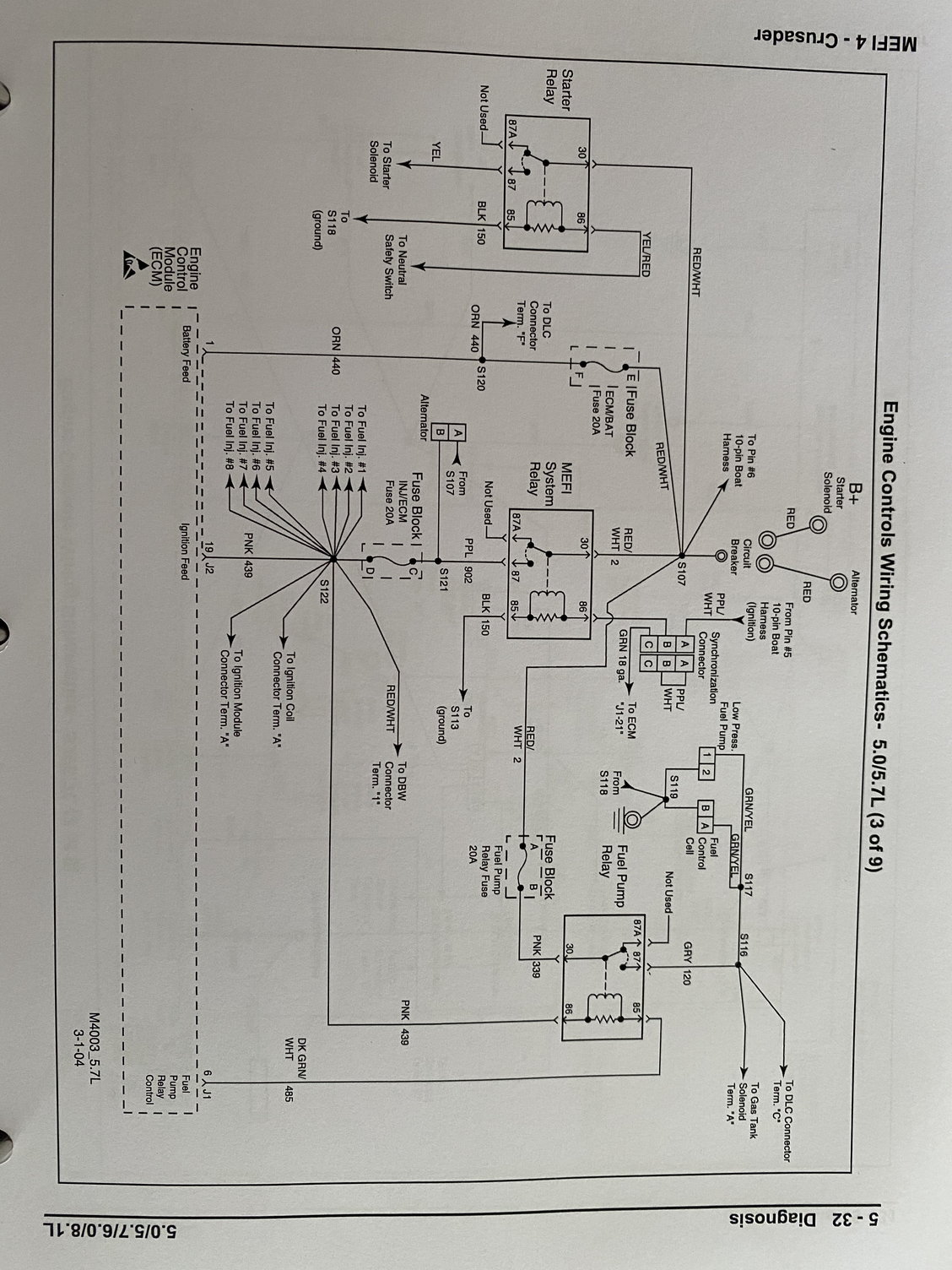
MEFI™ ECM. This is the MEFI™ ECM version 4. It has two connectors and three mounting bosses. Back side of the ECM. Note the part. number on the sticker. In this case "12575479". All MEFI™ ECM's have a part number like this that can be used to determine the "series" or "generation" that the MEFI™ system is. MEFI™ ECM version 1, 2. Wiring Schematics Distributor Kit Wiring Diagram J1939 to NEMA2000 Wiring MEFI 4 MEFI 4 Engine Controls Schematic 4.3L – 5.7L MEFI 4 ECM Circuit Board Layout (5.7-6.0-8.1L) MEFI 4 Engine Controls Schematic 6.0L MEFI 4 ECM Engine Wiring Diagram 8.1L 5.7L Wiring Harness Schematic (472605) MEFI 5 MEFI 5 Engine Controls Schematic 6.0L MEFI 5... MEFI 4 - PCM 6.0L. Fuel Metering System 3B - 11. 3. Once installed, pull on both sides of the fitting in order to make sure the connection is secure. 12787. 4. Install the retainer on to the quick-connect fitting. 1238589. MEFI 4 - PCM 3B - 12 Fuel Metering System. 6.0L Fuel Rail Assembly Replacement Remove or Disconnect 1. Relieve the fuel. You should be familiar with wiring diagrams, the meaning of voltage, ohms, amps and the basic theories of electricity.. (DLC) (Figure 1-1). It is part of the MEFI engine wiring harness, and is a 10-pin connector, which is electrically connected to the ECM. It is used in the assembly plant to receive information in checking that the engine is
Delphi Mefi 5 Delphi Wiring Diagrams is the eighth story in the Harry Potter series and the fir Delphi Mefi 5 Delphi Wiring Diagrams... Get free kindle Delphi Mefi 5 Delphi Wiring Diagrams or download adn read online kindle Delphi Mefi 5 Delphi Wiring Diagrams ebook.. Download PDF. Download ePub In wiki says that Delphi Mefi 5 Delphi Wiring... CAMP Systems is the industry's leading Aircraft Maintenance and Regulatory Compliance Management solution for fixed and rotor wing aircraft. CAMP's product suite includes Maintenance Management, Engine Health Monitoring, Inventory Management, Flight Scheduling and shop floor Enterprise Information Systems. The key to CAMP solutions is our Aircraft Analysts who are experienced aviation. ignition feed to ecm ignition feed from 10 pin ignition Ground Ignition Start Request Batt feed to ECM Fuel pump relay ground Power to fuel pump Ground A- Is the trans temp gauge sensor wire, I assume I need the sensor to go into the trans and I will be good to go on this one B1- connects to mefi module and goes through part of the existing harness B2- Open end with four wires- Red, Green, Black, and White C- Mefi 4 module that may be worthless D-back to gauges in dash.
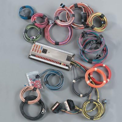
LS MEFI 4 Wiring Harness Diagram - Open and Download to Device. LS Green/Blue Wiring Harness Diagram - Open and Download to Device. LS Red/Blue Wiring Harness Diagram - Open and Download to Device. LS MEFI Relay Pak Wiring Harness Diagram - Open and Download to Device. LS2/LS3 Thermostat Identification - Open and Download to Device.
mefi 4 wiring harness diagram ls1 wiring diagram operations. Architectural wiring diagrams proceed the approximate locations and interconnections of receptacles, lighting, and permanent electrical services in a building. Interconnecting wire routes may be shown approximately, where particular receptacles or fixtures must be on a common circuit.
on Mefi 4 Wiring Diagram. You should be familiar with wiring diagrams, the meaning of voltage. 1 - 4. Section 1 - General Information. Marine. Scan Tool Use With Intermittents. 4. MEFI 4. Ignition "ON. " the ECM no longer receives a signal voltage within the The wiring schematics and circuit identifications are for the MEFI 4/4B.
4D-2 - WIRING DIAGRAMS 90-806535 893 Wiring Diagrams MCM 3.0L/3.0LX 1 2 4 3 1 2 3 4 5 6 3 1 2 1 2 3 NOTE : Gray lead for use with service tachometer. A-Ignition System
Mefi 4 Wiring Diagram from marinepowerusa . To properly read a wiring diagram, one offers to learn how typically the components in the program operate. For example , if a module is powered up and it sends out a signal of 50 percent the voltage and the technician does not know this, he'd think he has a challenge, as he or she would expect a.
required engine harness wiring change to 470 type engines with belt driven alternator smc-04-02 02-mar-2005. black sensor failures in mefi-3 mercury distributors smc-00-14 24-feb-2005. official recall notification u.s. boat federal boat safety act smc-05-01 22-feb-2005. electric fuel pump troubleshooting smc-04-01 30-jan-2004
MEFI 4 - PCM Marine Electronic Fuel Injection (MEFI) Section 1 General Information Contents. You should be familiar with wiring diagrams, the meaning of voltage, ohms, amps and the basic theories of electricity. You should also understand what happens if a circuit becomes open, shorted to ground
RAMJET 350 Electronic Fuel Injection (EFI) MEFI 3 to MEFI 4 Conversion Kit 12499116 Getting Started Installation of this upgrade kit is straight forward; however, installation of the exhaust bung requires welding.. If you have customized your wiring harness for your specific application it may be easier to only remove the
Mefi™ 4, 4a, 4b ECM`s. The ecm will ship blank and without a calibration. If available in our tune inventory, we are happy to place a baseline tune in the computer at no additional cost. Please call or email us for engine applications and program details. For specs, options and pricing.
And looking at the wiring diagram for MEFI 1 & 2, the green/white wire appears to provides +12 volts to the fuel pump relays coil on terminal 85, and terminal 86 is connecting the coil to ground via a black wire. This is different than MEFI 3 &; 4 where the ECM grounds the fuel pump relay circuit with the green/white wire.
I have a diagram of mefi 4 pinouts that I got off internet.I will take a photo. On another site on a forum one guy says to wire the o2 sensor wires 0-5 v to connector j2 pin 6 and the ground wire to j2 pin 3. As now my harness has no prvisions to plug a o2 sensor into. I need to do this myself.
A wiring diagram is a simplified traditional pictorial representation of an electric circuit. This diagram is a thumbnail. Here s a basic look at how the sensors in the speed density mefi 4 fuel injection work. Telecaster 4 way wiring diagrams this wiring diagram assumes you are using a metal control plate.
Fox Marine MEFI-1/2/3/4 Engine Gateway Installation and Operating Instructions Revised 05/29/21 Page 1 of 7 Thank you for your purchase of Fox Marine's MEFI Engine Gateway. The following details are provided for installation and operating instructions. These instructions are intended for hardware shipped on or after 07/01/20.
Monitor your MEFI 1, MEFI 2, MEFI 3,MEFI 4,MEFI 4A, MEFI 4B system. Scanner Pro is used for doing engine monitoring, data logging, and malfunction trouble code reading. We have developed MEFI 1, MEFI 2, MEFI 3, and MEFI 4 definition files that allow you to take full advantage of the features that Scanner Pro has to offer.














0 Response to "37 Mefi 4 Wiring Diagram"
Post a Comment