40 In Which Diagram Is The Current Through The Battery Nearly Zero?
A battery of emf 6 volt is connected across 0.30 m of resistance wire of diameter 1.0 mm. A current of 0.5 ampere flows through the wire. Question 13 (1984 Question 59) What current will flow if this wire is replaced by 1.20 m of the same wire? A circuit consists of a 12 volt battery and two 4 ohm resistors connected in series. Draw the circuit, The above circuit diagram shows a battery with an internal resistance of 4.0 ohms connected to a 16–ohm and a 20–ohm resistor in series. The current in the 20–ohm resistor is 0.3 amperes 11. What is the emf of the battery? (A) 1.2 V (B) 6.0 V (C) 10.8 V (D) 12.0 V 12.
A battery is a source of electric power consisting of one or more electrochemical cells with external connections for powering electrical devices such as flashlights, mobile phones, and electric cars.When a battery is supplying electric power, its positive terminal is the cathode and its negative terminal is the anode. The terminal marked negative is the source of electrons that will flow.

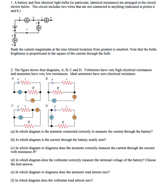
In which diagram is the current through the battery nearly zero?
circuit is 12Ω (0Ω+12Ω=12Ω) and the current through the motor is 2.0A. += 8 4 += 24 12 = 2.0 # Now if the resistance of variable resistor is set at 12Ω, then the total resistance of the circuit will be 24Ω (12Ω+12Ω=24Ω) and the current will += 24 24 = 1.0 # The current through the motor will have halved and the motor will run slower. To verify that resistances in series do indeed add, let us consider the loss of electrical power, called a voltage drop, in each resistor in Figure 2.According to Ohm’s law, the voltage drop, V, across a resistor when a current flows through it is calculated using the equation V = IR, where I equals the current in amps (A) and R is the resistance in ohms (Ω). The reverse arrow shows that the diode is reverse biased - the current is nearly zero; Rectifier. in a direct current or d.c. circuit, the current only flows in one direction, ie from positive to negative. The resistance of each lamp is shown on the diagram. The current through the battery is 2.00A. a. determine the current through each lamp
In which diagram is the current through the battery nearly zero?. Determine the current through each resistor, and the total current drawn from the battery. Solution: (a) Total resistance of the combination in parallel. (b) Potential of 20 V will be same across each resistor, so current. Question 5. At room temperature (27.0°C) the resistance of a heating element is 100 O. current from the battery compared to when only one bulb was connected. 1. Is Higher 2. Is Lower 3. Is The Same. the current in the circuit is 1. nearly zero 2. at a maximum and decreasing 3. nearly constant but non-zero. PRS24: 4/08/04 ... through the bottom resistor. So the Mar 21, 2017 · When the switch ‘S’ is closed, the current flows through the capacitor and it charges towards the voltage V from value 0. As the capacitor charges, the voltage across the capacitor increases and the current through the circuit gradually decrease. For an uncharged capacitor, the current through the circuit will be maximum at the instant of. A DC motor is an electric motor that runs on direct current (DC) electricity.DC motors were used to run machinery, often eliminating the need for a local steam engine or internal combustion engine.DC motors can operate directly from rechargeable batteries, providing the motive power for the first electric vehicles. Modern DC motors are nearly always operated in conjunction with power.
Nov 01, 2013 · Because the transistor is turned on, current flows through the transistor. It flows from the positive battery terminal, through R1, the LED, and the transistor down to the negative battery terminal. This makes the LED light up. The Components Used In The Light Detector Circuit. The resistor R1 controls the amount of current going through the. The batteries in each of the circuits shown above are identical and the wires have negligible resistance. In which circuit is the current furnished by the battery the greatest. (A) A. (B) B. (C) C. (D) D. (E) E. (E) Current is greatest where resistance is least. The resistances are, in order, 1 Ω, 2 Ω, 4 Ω, 2 Ω and. shown in the circuit diagram in the diagram below. (a)€€€€ Show that the resistance of the single equivalent resistor that could replace the four. Explain, without calculation, why the current through the battery increases in value from that in part (a).... of 6.0 Ω and the unit is connected to a 12 V dc supply having zero internal ... The primary function of a circuit is to allow electric current to pass through it safely. So, the first key element is the voltage source. It is a two-terminal device such as a battery, generators or power systems that provide a potential difference (voltage) between two points in the circuit so that current can flow through it. Element 3: Load
the magnetic field due to the counterclockwise current i in the larger loop is nearly uniform throughout the smaller loop. Suppose that x is increasing at the constant rate dx/dt = v. (a) Find an expression for the magnetic flux through the area of the smaller loop as a function of x. (Hint: See Eq. 29-27.) In the smaller loop, find (b) an. Jul 23, 2018 · The solenoid draws a continuous current of 700mA when energised and a peak of nearly 1.2A so we have to consider these things while designing the driver circuit for this particular Solenoid valve. Circuit Diagram. The complete circuit diagram for Solenoid driver circuit is shown in the image below. We will understand why it is designed so, once. A or C or D. If you asked which circuit correctly measures the current through the battery and the resistor load, then C or D are correct. in connection A, the current is almost zero, but the ammeter measures that low current. A, because the voltmeter, which is a high resistance, is connected in series with the battery. C or D. circuit is 12Ω (0Ω+12Ω=12Ω) and the current through the motor is 2.0A. += 8 4 += 24 12 = 2.0 # Now if the resistance of variable resistor is set at 12Ω, then the total resistance of the circuit will be 24Ω (12Ω+12Ω=24Ω) and the current will += 24 24 = 1.0 # The current through the motor will have halved and the motor will run slower.
An increase in battery voltage would increase the voltage drop across bulb Z (V Z) and thus provide a greater current through the bulb. A decrease in the resistance of bulb Z would also increase the current through the bulb. However, making a change in bulb X or Y would have no effect on the V Z / R Z ratio.
1. The battery drives a ccw current that, briefly, increases rapidly. 2. The flux through the top loop is upward and increasing. 3. To oppose the increase, the field of the induced current must point downward. 4. From the right-hand rule, a downward field needs a cw current. 5. The ccw current in the lower loop makes the upper face a north pole.
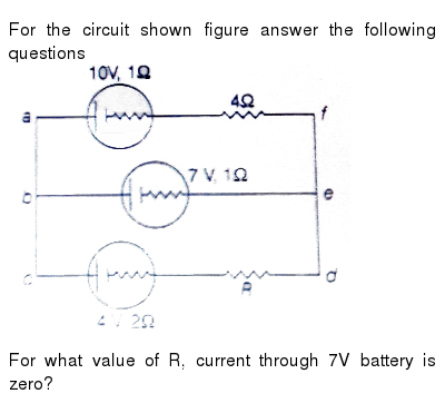
The combination is connected across a 2V battery of negligible resistance. Draw the diagram of the arrangement and calculate: (i) The current in each resistor A and C, (ii) The current through battery. Solution: The diagram of the arrangement is shown in Fig. Figure Based Long Answers
ANSWER: Correct In diagram A, the voltmeter is connected in series with the battery. Since the voltmeter has a very large resistance there is no (or nearly zero) current in the whole circuit. Therefore, the ammeter reads no current. In diagram B, the currentthrough the ammeter is the same as the current through the voltmeter.
In a conductive material, the moving charged particles that constitute the electric current are called charge carriers.In metals, which make up the wires and other conductors in most electrical circuits, the positively charged atomic nuclei of the atoms are held in a fixed position, and the negatively charged electrons are the charge carriers, free to move about in the metal.
To verify that resistances in series do indeed add, let us consider the loss of electrical power, called a voltage drop, in each resistor in Figure 2.According to Ohm’s law, the voltage drop, V, across a resistor when a current flows through it is calculated using the equation V = IR, where I equals the current in amps (A) and R is the resistance in ohms (Ω).
10. In the figure shown, an ideal battery of EMF = 12.0 V is connected to a network of resistances R1=6.0Ω, R2=12.0Ω, R3=4.0Ω, R_4=3.0Ω, and R5=5.0Ω. What is the current through resistor R5 ? We need to find the equivalent resistance of the circuit to find the total current supplied by the battery.
A defibrillator is designed to pass a large current through a patient's torso in order to stop dangerous heart rhythms. Its key part is a capacitor that is charged to a high voltage. The patient's torso plays the role of a resistor in an RC circuit. When a switch is closed, the capacitor discharges through the patient's torso.
The flow of current has been shown by dotted arrows in the figure. Thus the direction of flow of current through the load resistance R L remains the same during both half cycles of the input supply voltage. See the diagram below – the green arrows indicate the beginning of current flow from the source (transformer secondary) to the load.
4. RC Circuits VC = V 0 1e 1 ⇡ 0.63V 0 (4.4) VR = V 0 e 1 ⇡ 0.37V 0 (4.5) This means that after t = ⌧ seconds, the capacitor has been charged to 63% of its final value and the voltage across the resistor has dropped to
The reverse arrow shows that the diode is reverse biased - the current is nearly zero; Rectifier. in a direct current or d.c. circuit, the current only flows in one direction, ie from positive to negative. The resistance of each lamp is shown on the diagram. The current through the battery is 2.00A. a. determine the current through each lamp
Also calculate the current drawn by the circuit from the battery of emf. $6V$ and negligible internal resistance. (Image will be uploaded soon) Ans: It is given that no current flows through AO then the circuit is said to be a balanced Wheatstone bridge. $\Rightarrow \frac{2}{4}=\frac{3}{X}$ $\Rightarrow X=\frac{12}{2}=6$ $\Rightarrow X=6\Omega $
In diagram B, the current through the ammeter is the same as the current through the voltmeter. Since the resistance of the voltmeter is very large, the current is nearly zero. The last group of questions refers to a battery that has emf 12.0 volts and internal resistance 3.00 ohms.
Current is in the direction of the motion of a positive charge. so this means the current flows down the moving bar, to the left along the bottom conductor, up through the resistor, and to the right along the top conductor. That is a clockwise flow through the entire circuit. If the direction of the velocity is changed,
of the current passes through this path of nearly zero resistance. 7.4 Kirchhoff's Circuit Rules In analyzing circuits, there are two fundamental (Kirchhoff's) rules: 1. Junction Rule At any point where there is a junction between various current carrying branches, by
, the current through C what is V C, the voltage across C? A) Only I 2 0 B) Only V C 0 C) Both I 2 and V C 0 D) Neither I 2 nor V C 0 Why? We are told that C is initially uncharged (V Q/C) I 2 cannot be zero because charge must flow in order to charge C Calculation In this circuit, assume V, C, and R are known.
E. zero. 8. The magnetic field of a straight, current-carrying wire is. - This is path 1 in the diagram... • The total current through the rectangular path equals the current through each turn multiplied by the number of turns d d B ds Bl path 11 path ∫ ∫ ...
Physics questions and answers. 1) in which diagram (s) does the ammeter correctly measure the current through the battery ? 2) In which diagram is the current through the battery nearly zero? 3) In which diagram (s) does the ammeter correctly measure the current through the resistor with resistance "R" ? 4) In which diagram does the voltmeter.
This can be seen in the I-V curve. At positive voltages, the curve rises exponentially, indicating that current is free to flow through the device. At negative voltages, the current remains nearly at zero. However, a sufficiently large negative voltage (known as the 'breakdown voltage') will cause the diode to become conductive to negative current.
Charge flowing in t = 1 sec, q =I t = 2 × 1 = 2C Therefore, number of Ω electrons flowing through the conductor flowing in 1 s, 19 19 q 2 n 1.25 10 e 1.6 10− = = = × × Example 3: A negligibly small current is passed through a wire of length 15 m and uniform cross-section 6.0 × 10⁻⁷ m2 7 5 6 10 2 10 m7 15 ×× − and its resistance is.
If a "normal" looking wire and a resistor are in parallel on a simple circuit diagram, will any current pass through the resistor?. How is this possible, as the battery is only 5 V? Reply. Jan 19, 2015 #8 Bystander.... When one is the next thing to zero? Reply. Jan 19, 2015 #9 joel amos. 104 0. Bystander said: The wire has a nearly zero ...
A direct current circuit may contain capacitors and resistors, the current will vary with time When the circuit is completed, the capacitor starts to charge The capacitor continues to charge until it reaches its maximum charge (Q = Cε) Once the capacitor is fully charged, the current in the circuit is zero
Immediately after the switch is closed, the current supplied by the battery is (A) V/(R. 1 + R 2) (B) V/R 1 (C) V/R 2 (D) V(R 1 + R 2)/R 1 R 2 (E) zero When the switch is closed, the circuit behaves as if the capacitor were just a wire, shorting out. the. resistor on the right. A long time after the switch has been closed, the current supplied.
• The current through the capacitor is zero • The current through R = current through 2R • V capacitor = V 2R • V 2R = 2/3 V A circuit is wired up as shown below. The capacitor is initially uncharged and switches S1 and S2 are initially open. Now suppose both switches are closed. What is the voltage across the capacitor after a very.
Question: Part In which diagram is the current through the battery nearly zero? Learning Goal: To understand the concept of electromotive force and internal resistance; to understand the processes in one- loop circuits; to become familiar with the use of the ammoter and voltmeter. In order for the current in a conductor to exist continuously.
In Current and Resistance, we described the term 'resistance' and explained the basic design of a resistor.Basically, a resistor limits the flow of charge in a circuit and is an ohmic device where Most circuits have more than one resistor. If several resistors are connected together and connected to a battery, the current supplied by the battery depends on the equivalent resistance of the.










0 Response to "40 In Which Diagram Is The Current Through The Battery Nearly Zero?"
Post a Comment