39 Grasslin Defrost Timer Wiring Diagram
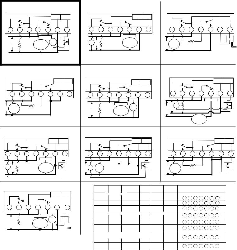
See wiring diagrams 8 & 9. 8240/6240 SERIES REPLACEMENT: The DTMV40 may be used to replace the Paragon 8240 or Precision 6240 series defrost timers with integral pressure termination the additionofa remotep essu e switchwi ed toter-Xp and p ofthe DTMV40 (with an 8240 series ter-label applied).The re must be noexte nal voltage Grasslin 9145 Defrost Timer Wiring Diagram. The terminals on the Digi 20A sub-base will accom-modate 10 to 24 AWG wire. To increase the duration of the defrost slide up the trippers that are adjacent to the starting time. Wire input to timer with the proper voltage marked on the unit.
grasslin defrost timer wiring diagram wiring diagram grasslin defrost timer wiring diagram wiring diagram. A set of wiring diagrams may be required by the electrical inspection authority to accept connection of the habitat to the public electrical supply system.
Grasslin defrost timer wiring diagram
Diagram Grasslin Defrost Timer Wiring Diagram Full Version Hd Quality Wiring Diagram Nvsengineers Hotel Patton Fr. The wires on your new switch are intended for black power. Grasslin time clock wiring diagram. Intermatic incorporated manufactures timer switches designed for indoor and outdoor use. Download 59 grasslin timer pdf manuals. Grasslin Timer Wiring Diagram. Grässlin UK Connect wiring in accordance with wiring diagram. Do not combine timer to control a load on a separate supply circuit, which can be a different. Wired incorrectly need wiring diagram. grasslin timer need to no what wires go were there are 4 wires coming out the timer red and brown together white and. In this video you can learn about the defrost timer wiring diagram of a frost free refrigerator and circuit diagram Step by step details about the function o...
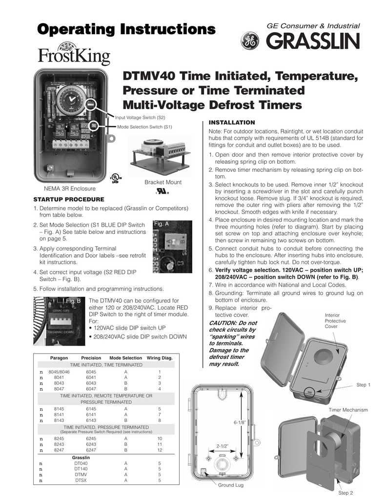
Grasslin defrost timer wiring diagram. The DTAV40 Defrost Timer is equivalent in function, terminal identification (with appropriate terminal block label attached), and wiring to the Paragon 8140 and Precision 6140 series Defrost Timers. The DTAV40 may also be used to replace Paragon 8040 and Precision 6040 series time terminated defrost timers. Grasslin Controls 40a Defrost Timer Wiring Diagram. Grasslin dtmv40 series operating intermatic dtav40 installation defrost timer auto time controls hvac r multi voltage 40 the heatcraft dtsz instructions warning risk of fire or electric shock. Intermatic Dtav40 Series Installation Operating Instructions Manual Pdf Manualslib. Heatcraft grasslin dtsz defrost timer t 49f wiring diagram swapping on intermatic dtav40 series installation refrigeration timers for warning risk of fire or electric shock dtsx b 240 time controls hvac r auto. Heatcraft Grasslin Dtsz Defrost Timer Installation And Operation Manual Manualzz. 010-0011B PLCs/Machine Control from INTERMATIC 2-Year Warranty - DISCONTINUED BY MANUFACTURER, DEFROST TIMER , PC BOARD, 40 AMP, 208-240 VAC
The Latest Paragon® Defrost Timer • Universal Defrost Timers (UDT) • Works with multiple voltages • Removes built up of ice and frost • Easy to install • Simple to program • Part 9145-00 temp terminated • Part 9045-00 time terminated • Available as mechanism only without case – Add “M” to end of part number Grasslin Defrost Timer Dtsx B 240 Wiring Diagram. Schematic Diagram Iphone 6s Plus. Pi Metal Detector Schematic Diagram.. Related Posts. 220v Electric Motor Wiring Diagram Pdf. How To Test Rv Furnace Circuit Board. What Happens To Amps In A Parallel Circuit. Why Is Voltage Not Shared In A Parallel Circuit. When the timer is toggled to the Off position, the timer or the electrical device won't operate. Dual trigger cord sets that give you the flexibility to stagger lighting schedules. Variety of intermatic 240v timer wiring diagram. 21A 24/120/208/240V Analog or Mechanical Timer Switch (FM1STUZ-120U) at Ferguson. 20. 4+. In this video you can learn about the defrost timer wiring diagram of a frost free refrigerator and circuit diagram Step by step details about the function o...
True Freezer T 49f Wiring Diagram. Grasslin Defrost Timer (Freezer Units Only). 13 TRUE will not warranty any refrigerator that has been.. louvered grill, wiring diagram is positioned on the. wires) N=White (Neutral) X=Purple (defrost termination) This info obtained from sheet included with the Grasslin Timer for the True Freezer. Grasslin Dtav40 Wiring Diagram. For electric heat, hot gas or compressor shutdown defrost. The Grässlin DTAV40 Series Auto Voltage Defrost Timer is applicable to air defrost (compressor. Intermatic/Grässlin's Defrost controls just got even better! The DTAV40 defrost control automatically selects the appropriate voltage between Wiring Diagrams. Wiring Diagram - Freezer ½ to 2 HP Single Phase... Set the correct time of day on the defrost timer. Do not set a cooler thermostat below the walk-ins design temperature or product Diagram 9 - Typical Wiring Diagram for Single with Defrost Timer Only.Jul 02, · I can increase the defrost time (Grasslin timer), but don't believe it will be. Grasslin Defrost Timer Wiring Diagram Best Image rhdiagramoceanodigitalus along with Paragon Timer Wiring Diagram And Whirlpool From Rhfharatesinfo or Paragon Timer 20 Wiring Diagram Free Download \u Playapkcorhplayapkco in addition Paragon Timer Wiring Diagram In Addition To Sell Sheet With Rhfharatesinfo further Paragon Timer.
Operating Instructions
Grasslin Defrost Timer Wiring Diagram. July 25, 2018. Grasslin Defrost Timer Wiring Diagram powerful and user friendly time switches products for light and temperature control energy and hour metersTime Switch Technology HVACR Light Control Meters Imprint Grasslin Defrost Timer Wiring Diagram media inriver 6788 8171 ashx DTAV40 Fi ier PDFThe Gr.

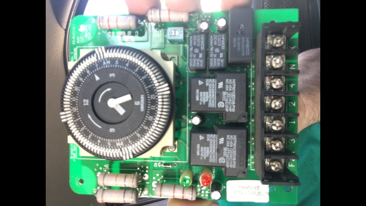
True Mfg Defrost Time Clock Youtube
T 49f Wiring Diagram Swapping Timer On True T49f Freezer From Grasslin Dtsx Im 120tm To A Supco S814100 I Need Wirecolor. Diagram 8145 20 Defrost Timer Wiring With Temp Termination Full Version Hd Quality. Defrost Timer For True Part 831993 Restaurant Equipment Parts Food Service Partsfps.

Intermatic Dtav40m Intermatic Grasslin 120 240v 40a Nema3r Defrosttmr
Description: Paragon Defrost Timer 8145 20 Wiring Diagram – Schematics And within Grasslin Defrost Timer Wiring Diagram, image size 450 X 1088 px, and to view image details please click the image.. Here is a picture gallery about grasslin defrost timer wiring diagram complete with the description of the image, please find the image you need.
Universal Defrost Timers 9145 9045 Series
Diagram Grasslin Defrost Timer Wiring Diagram Full Version Hd Quality Wiring Diagram Nvsengineers Hotel Patton Fr. The wires on your new switch are intended for black power. Grasslin time clock wiring diagram. Intermatic incorporated manufactures timer switches designed for indoor and outdoor use. Download 59 grasslin timer pdf manuals.

Grasslin Dtmv40 Universal Defrost Timer
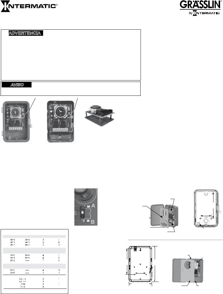
The Grasslin DTAV40 defrost control is field adjustable for 120V or 240V operation and shall have defrost initiation times settable to the quarter hour via captive trippers at 15 minute intervals. The defrost timer is housed in a NEMA 3R indoor/outdoor plastic enclosure. The relay output is 40A Resistive, 2HP @ 250VAC.

Streamline Defrost Timer Installations With Intermatic S
Grasslin Timer Wiring Diagram. Grässlin UK Connect wiring in accordance with wiring diagram. Do not combine timer to control a load on a separate supply circuit, which can be a different. Wired incorrectly need wiring diagram. grasslin timer need to no what wires go were there are 4 wires coming out the timer red and brown together white and.
Defrost Time Controls Hvac R Defrost Time Controls Hv Ac R
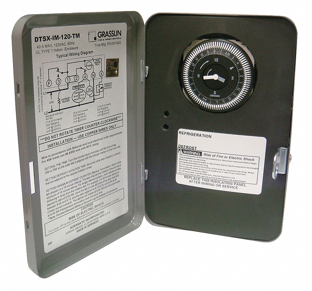
T-49f wiring diagram: Swapping timer on True T49F freezer, from Grasslin DTSX-IM-120TM to a Supco S814100 timer, I need - Answered by a verified HVAC Technician

Basic Electrical Wiring Sink Ground Fault Circuit Breaker
Through the thousand images on the net concerning grasslin defrost timer wiring diagram, we all selects the top series with greatest quality simply for you, and now this pictures is considered one of graphics choices within our ideal pictures gallery in relation to Grasslin Defrost Timer Wiring Diagram.I really hope you can like it. That impression (Paragon Timers And Manuals: throughout.

Economic And Efficient Grasslin Defrost Timer Wiring Diagram
Aviation History magazine is an authoritative, in-depth history of world aviation from its origins to the Space Age. Aviation History offers air enthusiasts the most detailed coverage of the history of manned flight, with action-packed stories and illustrations that put the reader in the cockpit with pilots and military (Army, Navy, and Marines) aviators to experience aviation’s greatest dramas.
How To Diagnose A Defective Freezer Defrost Time Clock
Grasslin 40a Defrost Timer Wiring Diagram – wiring diagram is a simplified usual pictorial representation of an electrical circuit. It shows the components of the circuit as simplified shapes, and the power and signal friends amongst the devices. A wiring diagram usually gives guidance approximately the relative direction and covenant of.

Intermatic Product Catalog Pages 101 150 Flip Pdf
The DTAV40VMVM Defrost Timer is equivalent in function, terminal identification (with appropriate terminal block label attached), and wiring to the Paragon 8140 and Precision 6140 series Defrost Timers. The DTAV40VM may also be used to replace Paragon 8040 and Precision 6040 series time terminated defrost timers.
Auto Voltage Defrost Timers 8000 Series
defrost timer shall incorporate voltage monitoring to protect against low-voltage conditions. The defrost timer shall also incorporate a short cycle delay adjustable from 0 sec. (off), 6 sec. minimum to 10 min. max to prevent rapid compressor cycling. The defrost timer shall be housed in a UL Type 3R indoor/ outdoor plastic enclosure.
Auto Voltage Defrost Timers 8000 Series
Universal Defrost Timers 9145 9045 Series. Diagram grlin timer wiring older frigidaire defrost refrigerator time controls hvac r heatcraft grasslin dtsz whirlpool in frost free owner manual for 2008 alpha sun e3 hvacr and devices ppt bypass basic page timers 2002 vz800 full wolff tanning g series zx32 3fh universal 9145 9045 2100 177 manualzz diagrams by lindy fralin icm550 radioactive beam.
Installation Amp Operating Instructions
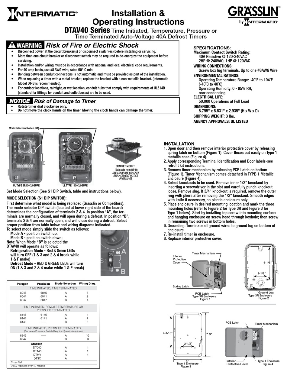
Intermatic DTAV40 Series Installation & Operating Instructions Manual. First determine what model is being replaced (Grasslin or Competitors). determines the configuration of terminals 2 & 4. In position " A ", the ter -. minals are normally closed, and will open during a defrost. In position " B", terminals 2 & 4 are normally open.
Intermatic Dtav40 Series Installation Amp Operating
The DT AV40 will replace all models of Paragon 8040, 8140,8240 Series or Precision 6040, 6140 Series and all prior Grasslin Defrost T imer models. TERMINAL IDENTIFICA TION: The standard DT AV40 terminal identification is identical to the Paragon 8145 with the addition of the "F" terminal.

How Freezer Defrost Timer Operates
Aug 18, 2021 · More than a year-and-a-half into the COVID-19 pandemic, burnout seems to be on everyone’s lips. Many of us didn’t realise what had hit us when we scrambled to adjust to the sudden upheaval of the workplace, switching to remote work with little or no preparation, or deemed an essential worker and asked to continue business-as-usual in highly unusual circumstances.
Multi Voltage Defrost Timer
Heatcraft grasslin dtsz defrost timer installation and operation manual manualzz t 49f wiring diagram swapping on true t49f freezer from dtsx im 120tm to a supco s814100 i need wirecolor intermatic dtav40 series operating instructions pdf manualslib warning risk of fire or electric shock caution damage refrigeration timers for refrigerators freezers b 240 dtsx240 21340101 8219056 8145 8045.

Intermatic Timers And Manuals
Grasslin Defrost Timer Wiring Diagram, Wholesale Various High Quality Grasslin Defrost Timer Wiring Diagram Products from Global Grasslin Defrost Timer.15 results for "grasslin defrost timer" Intermatic DTAV40 //v Time Initiated, Time Or Remote Temperature Or Pressure Terminated In Nema 3r Outdoor Plastic Enclosure. by Intermatic. $ $ 96 00.
Icm550

Intermatic Defrost Timers And Manuals
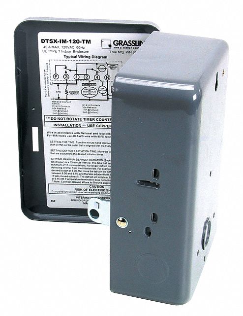
Timer Defrost Dtsx Im 120 Fits Brand True T 49 Twt 67f

Grasslin Dtmv40 Series Operating Instructions Manual Pdf
Defrost Time Controls Hvac R Defrost Time Controls Hv Ac R

T 49f Wiring Diagram Swapping Timer On True T49f Freezer
Intermatic Dtav40 Series Owner S Manual
Intermatic Dtav40 Series Owner S Manual
Defrost Time Controls Hvac R Defrost Time Controls Hv Ac R

13 3d Flooring Ideas In 2021 3d Flooring Washing Machine
Auto Voltage Defrost Timer

Refrigeracion Comercial Defrost Timer
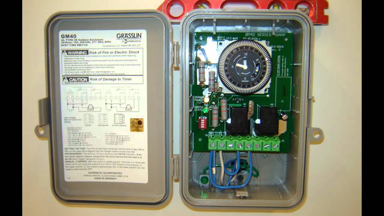
Gm 40 Time Clock

Robertshaw 8143 20 208 240v 40amp Defrost
Dtsx Time Initiated Temperature Pressure Or Time Terminated
Defrost Time Controls Hvac R Defrost Time Controls Hv Ac R

Intermatic Defrost Timers And Manuals
Icm550

Typical Wiring For Defrost On A Single Evaporator Freezer
Defrost Timer

Grasslin Time Clock Set Up Instructions
0 Response to "39 Grasslin Defrost Timer Wiring Diagram"
Post a Comment