41 Avr Generator Schematic Diagram
Voltage Regulator For Synchronous Generator. China Generator Avr Circuit Diagram Sx460 3 Phase Automatic Voltage Regulator. Automatic Voltage Ilizer Circuit Scientific Diagram. Adetrap Association Pour Le Développement De Traput 33 Generator Avr Circuit Diagram. Voltage Regulator For Synchronous Generator. Generator set with TELYS control panel. Follow the wiring diagram supplied by the manufacturer. SDMO. Nexys 2. Instructions for use. Réf. constructeur: V 20/09/.. module via a wiring harness, a terminal block (2 terminals) and a wiring harness for.Sdmo Generator Parts Diagram: This is images about sdmo generator parts diagram posted by Jeremy.
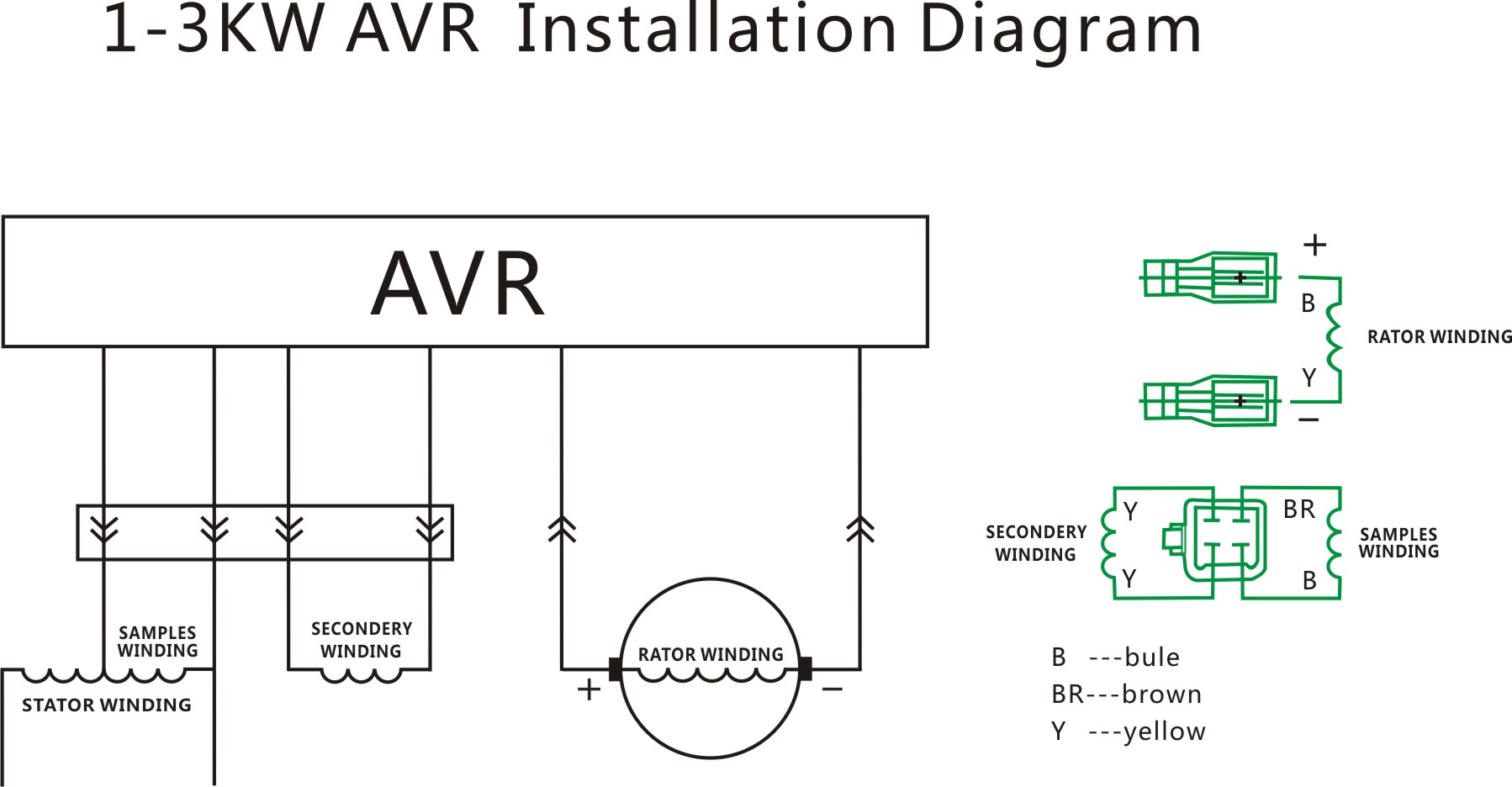
ABB Generators Ltd. 8AMG 5855292 en C 2 1. GENERAL INFORMATION 1.1 DESCRIPTION EA63-5 is an automatic voltage regulator (AVR) for AMG synchronous generator industrial application series. The AVR is typically supplied by a single-phase auxiliary winding wound into the stator slots.

Avr generator schematic diagram
13+ Draw The Schematic Diagram Of Automatic Voltage Regulator Of Ac Generator. For this matter an appropriate voltage regulator circuit is designed which can operate up to capacity. An automatic voltage regulator (avr) is commonly used in the generator excitation system of hydro and thermal power plants to regulate generator voltage and. Read Book Generator Avr Circuit Diagram Generator Avr Circuit Diagram As recognized, adventure as well as experience roughly lesson, amusement, as with ease as union can be gotten by just checking out a ebook generator avr circuit diagram as well as it is not directly done, you could bow to even more in the region of this life, just about the world. Px 300k1 Series A C Generators Automatic Voltage Control Schematic Diagram Of Alternator Auto Voltage Regulator Wiring Wiring Diagram Cable Ss15a3p Figure 4 13 Circuit Diagram For Voltage Regulator Circuit Hydro Power Plants Avr Automatic Voltage Regulator Circuit Diagram Voltage Stabilizer Wiring Diagram M2 3 Phase Voltage Regulator Wiring Diagram All Diagram Circuit Diagram Voltage […]
Avr generator schematic diagram. Basler Automatic Voltage Regulator (AVR) Accessory Manuals APM 2000 - 9147300990 Basler Electric Co. Parallel Module ©2003 10/03 CBS 305 - 9200700990 Basler Electric Co. Current Boot System ©2002 04/02 7 Wires 3 5kw Three Phase Generator Avr China Alternator Voltage Regulator. Voltage Regulator For Brushless Synchronous Generator With Harmonic Excitation Winding. 40 5kw Generator Avr Circuit Diagram. China Genset Avr Circuit Diagram 3 Phase 150kva 220 Volt Automatic Voltage Regulator Generator Sx440 Ac Brushless. AVR DDS specification. AVR DDS signal generator V2.0 is a firmware-based DDS signal generator that uses slightly modified Jesper's mini DDS algorithm adapted to AVR-GCC C code as in-line ASM.. The AVR DDS signal generator has two outputs - one for DDS signal and another for high speed [1, 8MHz] square signal - which may be used to bring back to life microcontrollers with wrong fuse. Px 300k1 Series A C Generators Automatic Voltage Control Schematic Diagram Of Alternator Auto Voltage Regulator Wiring Wiring Diagram Cable Ss15a3p Figure 4 13 Circuit Diagram For Voltage Regulator Circuit Hydro Power Plants Avr Automatic Voltage Regulator Circuit Diagram Voltage Stabilizer Wiring Diagram M2 3 Phase Voltage Regulator Wiring Diagram All Diagram Circuit Diagram Voltage […]
Avr Generator Circuit Diagram Imarksweb . Download: Avr Generator Circuit Diagram found on Marks Web of Books and Manuals. AVR DDS signal generator V2.0. Part 1. Schematic Oscillators. First AVR DDS V1.0 generator was only an attempt of running DDS algorithm without any amplitude control. Circuit diagram and PCB: Click to enlarge. Audio Frequency Generator Circuit. Stamford Generator 1250 Kva Wiring Diagram Wiring Diagram. 3 Phase Generator Wiring Diagram With Pmg And Mx 341 Avr Wiring. Briggs And Stratton Power Products Mgre7560 00 Promax 7500 6000ea. Mengenal Wiring Diagram Avr Generator Ac 3 Phase Dan Fungsinya. Pancake Generator. Basically the AVR or Automatic Voltage Regulators function for generator is to ensure voltage generated from power generator running smooth to maintain the stable voltage in specified limit. It can stabilize the voltage value when suddenly change of load for power supply demand. If the generator running in parallel condition,the AVR can controlled the voltage […] For better understanding of principle of Automatic Voltage Regulator i.e. AVR, we will first have a brief look on Generator Excitation System. I am here taking static excitation system for example. As we know that in static excitation system Generator output is fed to a thyristor bridge rectifier.
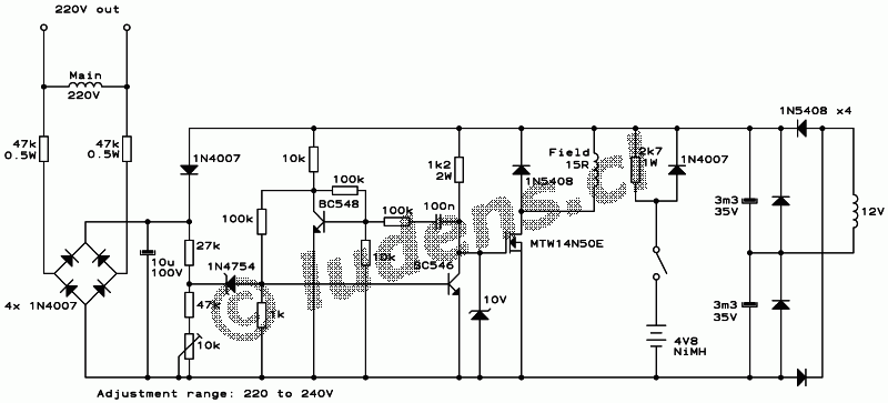
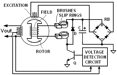
REGULATOR SCHEMATIC The diagram below shows a generic AVR implementation. This type of circuit has been around for years. Its numerous variations are found in both portable generators and automotive alternators and are described in various patents, such as General Motor's US3376496 for 3-phase applications and Honda's US6522106. Bookmark File PDF Generator Avr Schematics And Repair Manual Generator Avr Schematics And Repair Manual Thank you utterly much for downloading generator avr schematics and repair manual.Maybe you have knowledge that, people have see numerous period for their favorite books subsequently this generator avr schematics and repair manual, but end going on in harmful downloads. Schematic Diagram Automatic Voltage Regulator By facybulka Posted on July 21, 2017 7 views.. schematic diagram of automatic voltage regulator of ac generator Post navigation. Previous post External Voltage Regulator Wiring Diagram Dodge. Next post Epiphone Les Paul Wiring Diagram. The Synchronising circuit is used to keep the Ramp Generator and Low Hz Detector locked to the generator waveform period. The Low Pass Filter prevents distorted waveforms affecting the operation of the AVR control circuit. The Short Circuit Detector senses the presence of a short circuit on the generator output and forces the
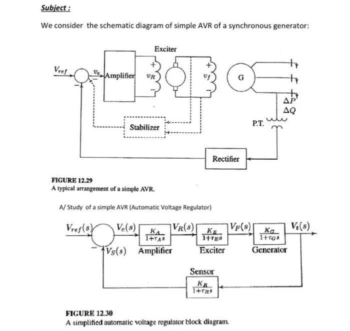
Solved Subject We Consider The Schematic Diagram Of Simple
Pls can you help me with the schematic diagram of AVR circuit for generator or alternator.thank u. Reply. Rajat Dhiman says 19/05/2016 at 2:58 PM. we have naren excitaion panel.. problem is that our excitaion is not reach at desireable level..due to this.generating voltage is not increases ..what i do.

Avr 10kw Automatic Voltage Regulator For 7 10kw Generator
Read Book Generator Avr Circuit Diagram Generator Avr Circuit Diagram As recognized, adventure as well as experience roughly lesson, amusement, as with ease as union can be gotten by just checking out a ebook generator avr circuit diagram as well as it is not directly done, you could bow to even more in the region of this life, just about the world.

Electric Machines Kirloskar Avr Kavr 1 Circuit Diagram
avr model r610 3 3 table of content cards reference 4 general description 5 mimic diagram excitation - regulation - shunt + booster 5 mimic diagram excitation - regulation - arep 7 mimic diagram excitation - regulation - pmg 8 connectics 9 generator / mains i/o (1f / 2f) 13 supply card 16 sensing card 18 pid, limit card 20
Wiring Diagram Avr Generator 12 Volt Generator Wiring
13+ Avr Generator Schematic Diagram. The firmware ensures that the circuit is recognised by the pc as a serial port and communicates with avr studio, the standard atmel. There are four reasons why you must know circuit diagram of generator avr. Generator avr circuit diagram pdf from opus28 It's time…
Buy Brushless Type Of Aspire Avr Synchronous Generator Spare
Voltage Ford Diagram Wiring Generator Regulatorto - Wiring Diagrams Hubs - Voltage Regulator Wiring Diagram. Wiring Diagram includes several in depth illustrations that show the connection of varied things. It consists of guidelines and diagrams for different varieties of wiring techniques and other items like lights, home windows, and so.

1 Schematic Diagrams Of Lfc And Avr Of A Synchronous
Post: Circuit diagram of generator avr. Audio tone generator using avr microcontroller: circuit, The circuit presented here demonstrates how to generate audible frequency from an avr microcontroller. the output of microcontroller is always digital so to generate. Sound generator circuit - electronic circuits and diagram, Simple sound.

Marelli Generator Avr Circuit Diagram Avr M40fa640a For
Voltage Regulator For Brushless Synchronous Generator With Harmonic Excitation Winding. China Single Phase Generator Avr Circuit Diagram R448 Avr Card For Diesel Engine China R448 Single Phase Avr. Diagram Rs232 Schematic Diagram Full Version Hd Quality Schematic Diagram Pvdiagramsperesc Gisbertovalori It. Wiring Diagram Of 5kva Generator.

How To Build An Avr For A Three Phase Generator Cr4
EXCITATION AND AUTOMATIC VOLTAGE REGULATOR SYSTEM 1/2 TABLE OF CONTENTS 1. OBJECTIVE AND FIELD OF APPLICATION 2. APPLICABLE STANDARDS AND GUIDES 3. DEFINITIONS 3.1. Discharge Circuit 3.2. Initial Excitation Circuit 3.3. Power Stage 3.4. Generator Full Load 3.5. Generator No Load 3.6. Field Switch 3.7. Alarm and Signaling Panel 3.8. Protection 3.9.
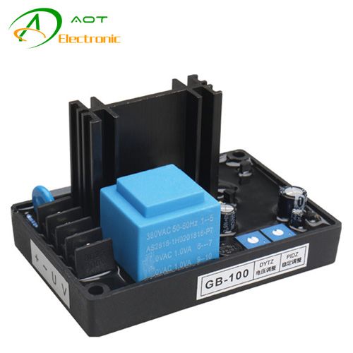
Brush Generator Circuit Diagram Avr Gb 100
generator avr circuit diagram automatic voltage regulator avr for generators. electronic circuits schematics diagram for free. simple electronic random number generator circuit using. ldmicro ladder logic for pic and avr cq cx. arduino tone generator circuit diagram and code. mitsubishi electric power system stabilizer. 555 timer pwm generator.

Schematic Diagram Of An Avr System Download Scientific Diagram
MX341 is a two phase sensed Automatic Voltage Regulator and forms part of the excitation system for a brush-less generator. Excitation power is derived from a three-phase permanent magnet generator (PMG), to isolate the AVR control circuits from the effects of non-linear loads and to reduce radio frequency interference on the generator terminals.
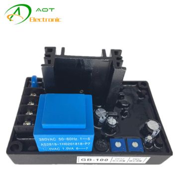
Brush Generator Avr Circuit Diagram Gb 100 Single Phase 10a
Schematic Diagram Of Lfc And Avr Of A Synchronous Generator Download Scientific Diagram. Brush Generator Circuit Diagram Avr Gb 100. Voltage Regulator For Brushless Synchronous Generator With Harmonic Excitation Winding. Shaluo Nice Sx440 Alternator Internal Avr Circuit Diagram Of Automatic Voltage Regulator Generator Part Repairing Accessories.

Solved 5 487 Il 4g دفعة 40 Series 3 1 Pdf Subject We
Generator Avr Connection Diagram. China generator avr circuit diagram voltage regulator for synchronous automatic alternator brushless brush spare parts single phase promax 9000ea continental 7 wires 3 5kw three. China Generator Avr Circuit Diagram Sx460 3 Phase Automatic Voltage Regulator. Automatic Voltage Regulator Avr For Generators.
Voltage Regulator For Synchronous Generator
13+ Draw The Schematic Diagram Of Automatic Voltage Regulator Of Ac Generator. For this matter an appropriate voltage regulator circuit is designed which can operate up to capacity. An automatic voltage regulator (avr) is commonly used in the generator excitation system of hydro and thermal power plants to regulate generator voltage and.

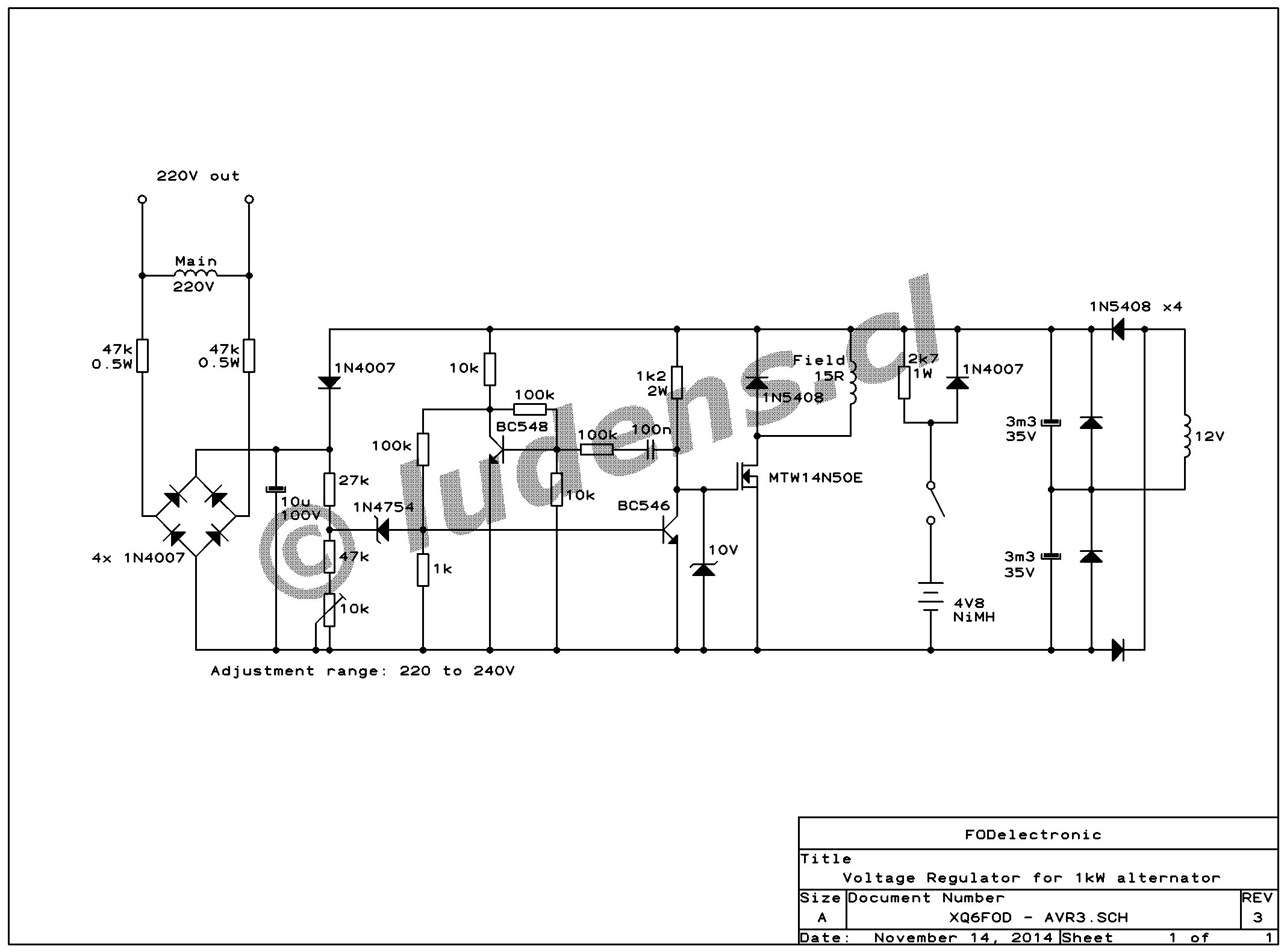
Avr 1 3 2 5 Kw 3kw 5kw Schematic Diagram For Generator Pdf
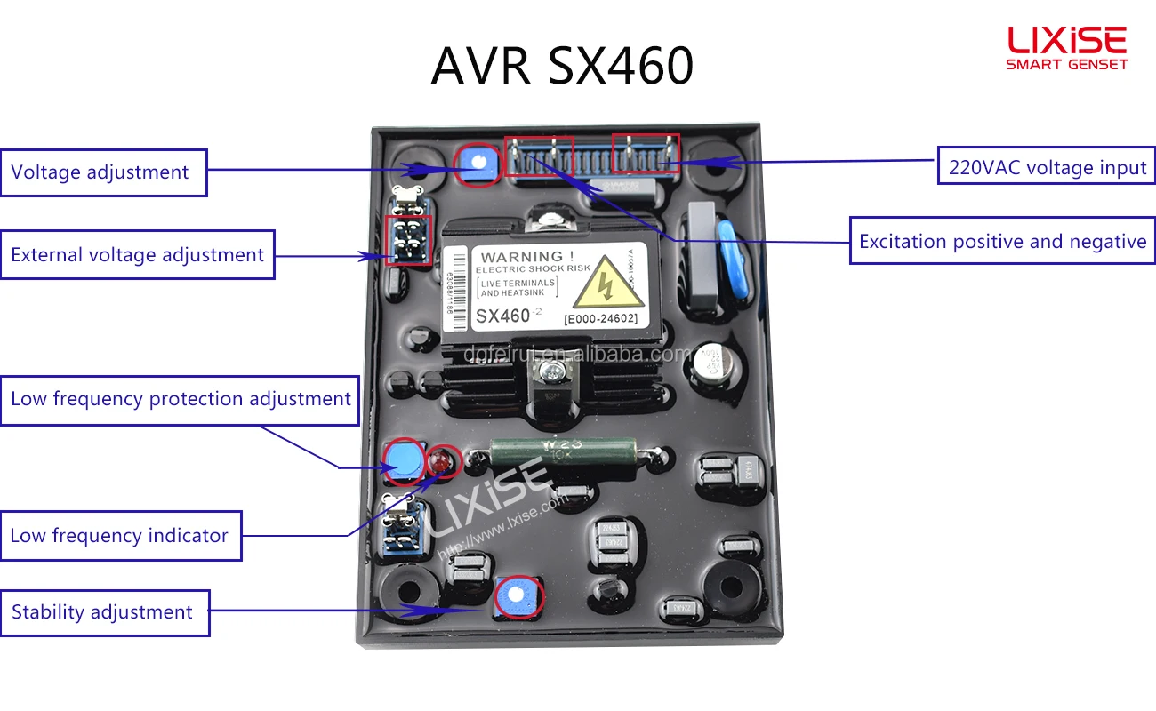
The AVR includes a stability or damping circuit to provide good steady state and transient performance of the generator. The correct setting can be found by running the generator at no load and slowly turning the stability control anti-clockwise until the generator voltage starts to become unstable.

Ozone Generator High Power Ionizer Circuit

China Single Phase Generator Avr Circuit Diagram R448 Avr

Block Diagram Of The Avr Architecture
Generator Avr Circuit Diagram Single Phase Avr 100kva 100kw
Xp4400e Avr Wiring Power Equipment Forum
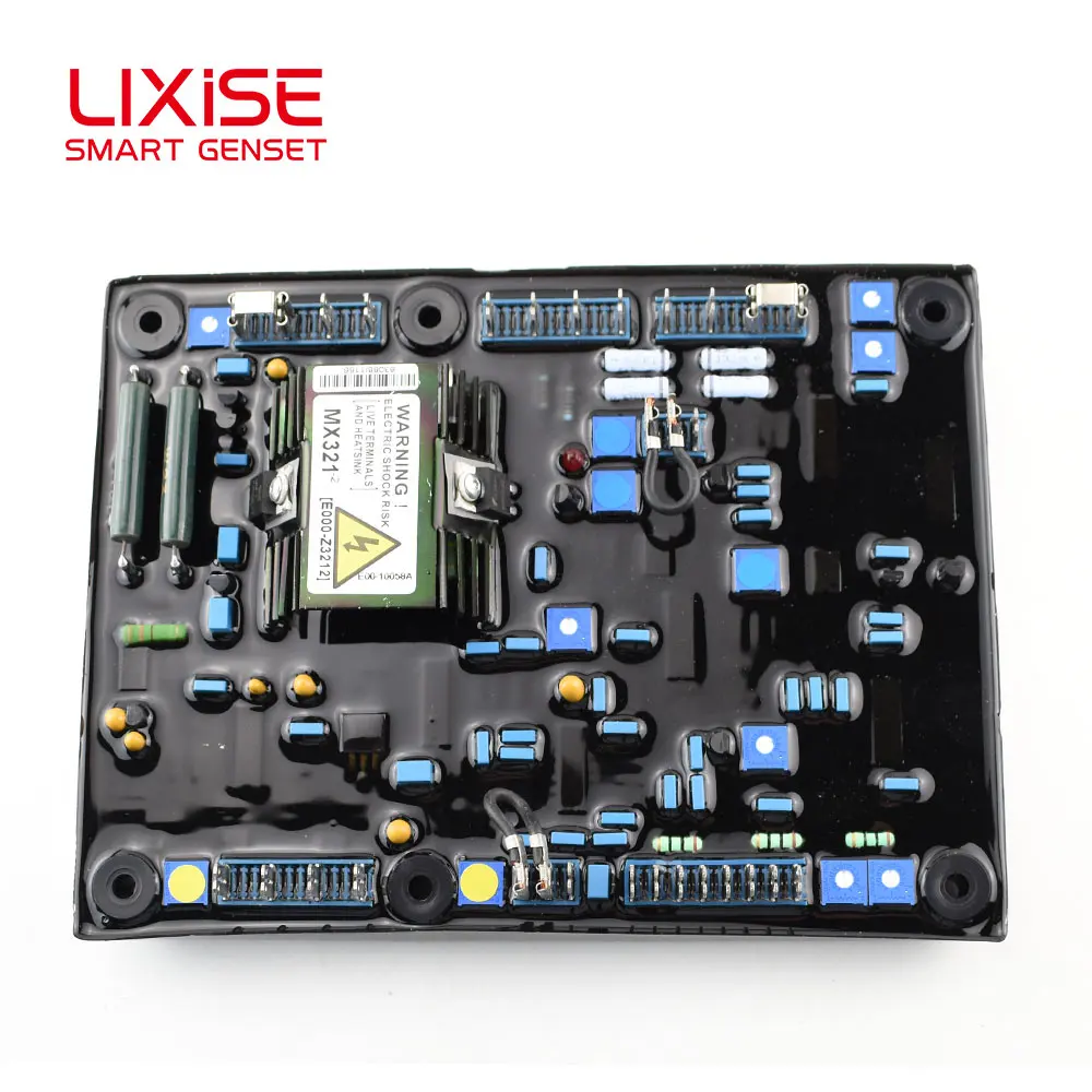
Diagram Sirkuit Regulator Tegangan Otomatis Avr Mx321 Buy Genset Avr Mx321 Voltage Regulator Circuit Diagram Product On Alibaba Com
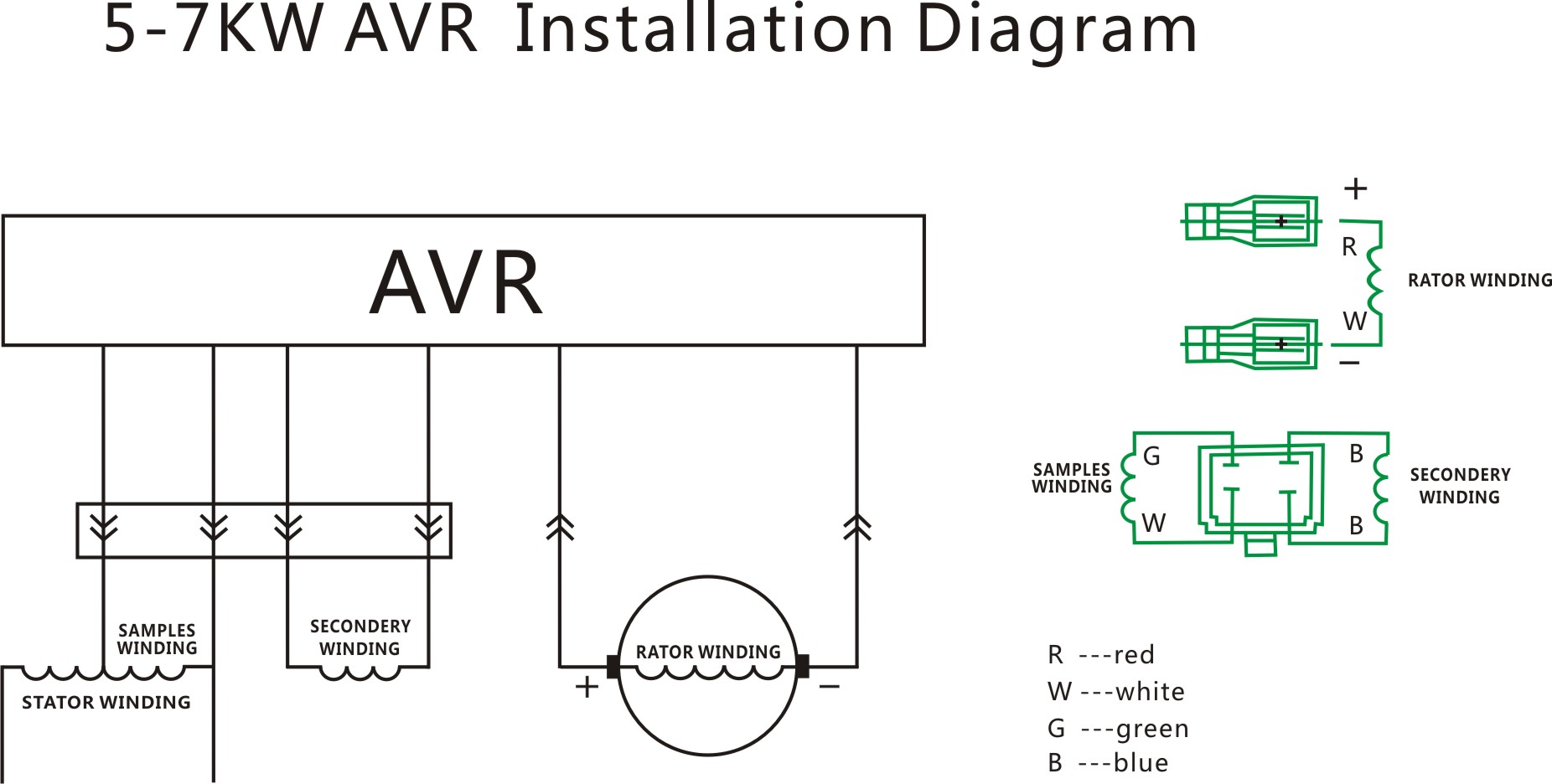
What Is 5 7kw Avr China Generator Avr Alternator Voltage

1 Schematic Diagrams Of Lfc And Avr Of A Synchronous
Trending Products Generator Avr Circuit Diagram P825d5 50hz
What Is 1 3kw Avr China Generator Avr Alternator Voltage

Product Tags Circuit Diagram Board Stabilizer Engine
Dds Signal Generator
Generator Listrik Desain Pcb Skema Diagram Sirkuit Avr Buy
Automatic Voltage Regulator Avr For Generators
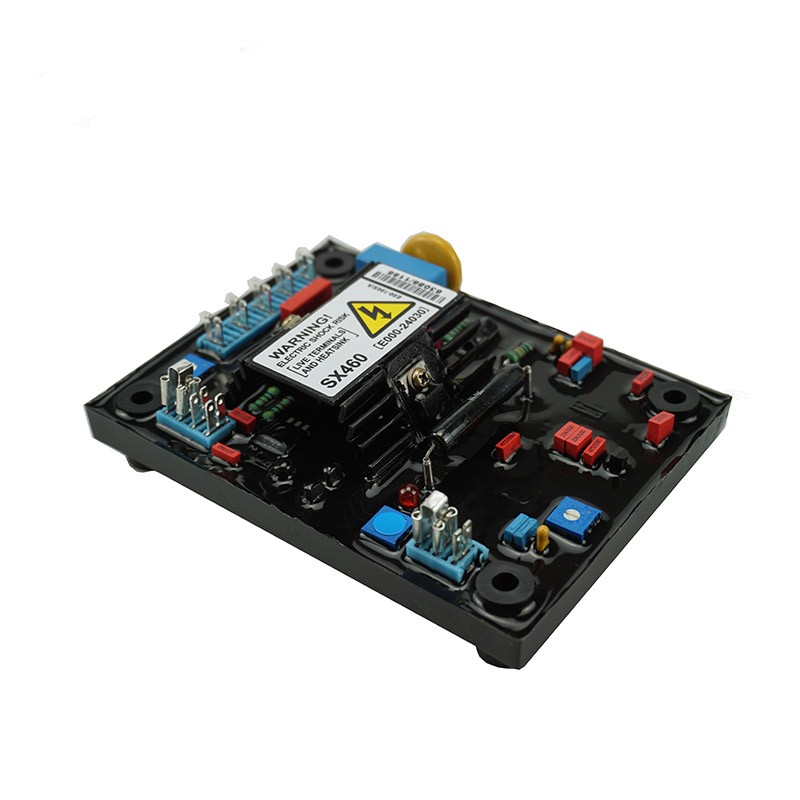
Stamford Avr Generator Avr Sx460 Genset Avr

Universal Diesel Cars Automatic Voltage Regulator Circuit
China Brush Generator Spare Parts Circuit Diagram Regulator

Jenis Brushless Dari Aspire Avr Generator Sinkron Suku Cadang Avr R250 Circuit Diagram Automatic Voltage Regulator
Voltage Regulator For Synchronous Generator
6ga2 491 1a Circuit Diagram Avr Ac Automatic Voltage Stabilizer For Genset Diesel
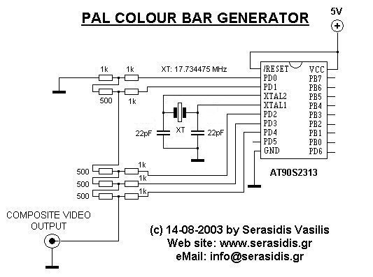
Avr Composite Pal Color Bar Generator

Generator Spare Parts Universal Regulator Avr 15a Circuit

Kualitas Tinggi 1 Pc Generator Avr Circuit Diagram Voltage Stabilizer Avr Gfc9 1a3g Untuk Genset Kipor Genset
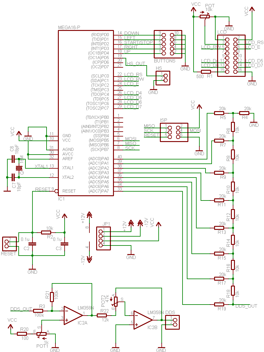
Avr Dds Signal Generator V2 0 Do It Easy With Scienceprog

China Cheap Generator Engine Circuit Diagram Automatic

Free Generator Avr Circuit Diagram Free Generator Avr

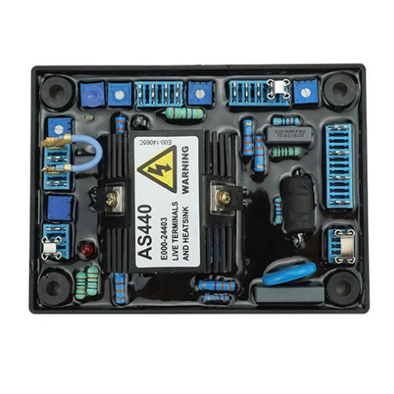
Jual Avr As440 Circuit Diagram Replacement Brushless
0 Response to "41 Avr Generator Schematic Diagram"
Post a Comment