43 Residential Steam Boiler Piping Diagram
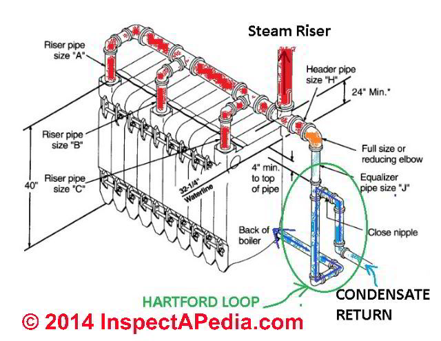
However, the piping pitch is much more crucial to this system. The piping must have pitch or fall to help the steam rise, and more importantly, to allow the condensate to flow back to the boiler. Level piping holds water, so it must have fallen. Also, a Hartford Loop is required to connect the supply and return. boiler and boilermate piping diagram. I am looking for a good piping diagram for a weil-mclane boiler and an indirect water heater system.There will be 3 zones controlled with zone valves,plus the zone for the heater.Boiler will be a cg-4 with a standing pilot. (80%).Need one that shows expansion tank location,pressure reducer valve,any and all.
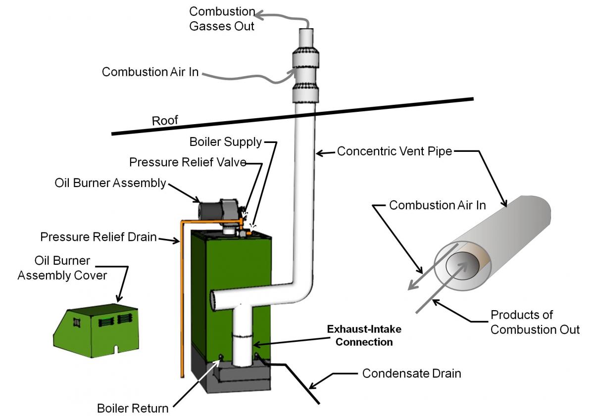
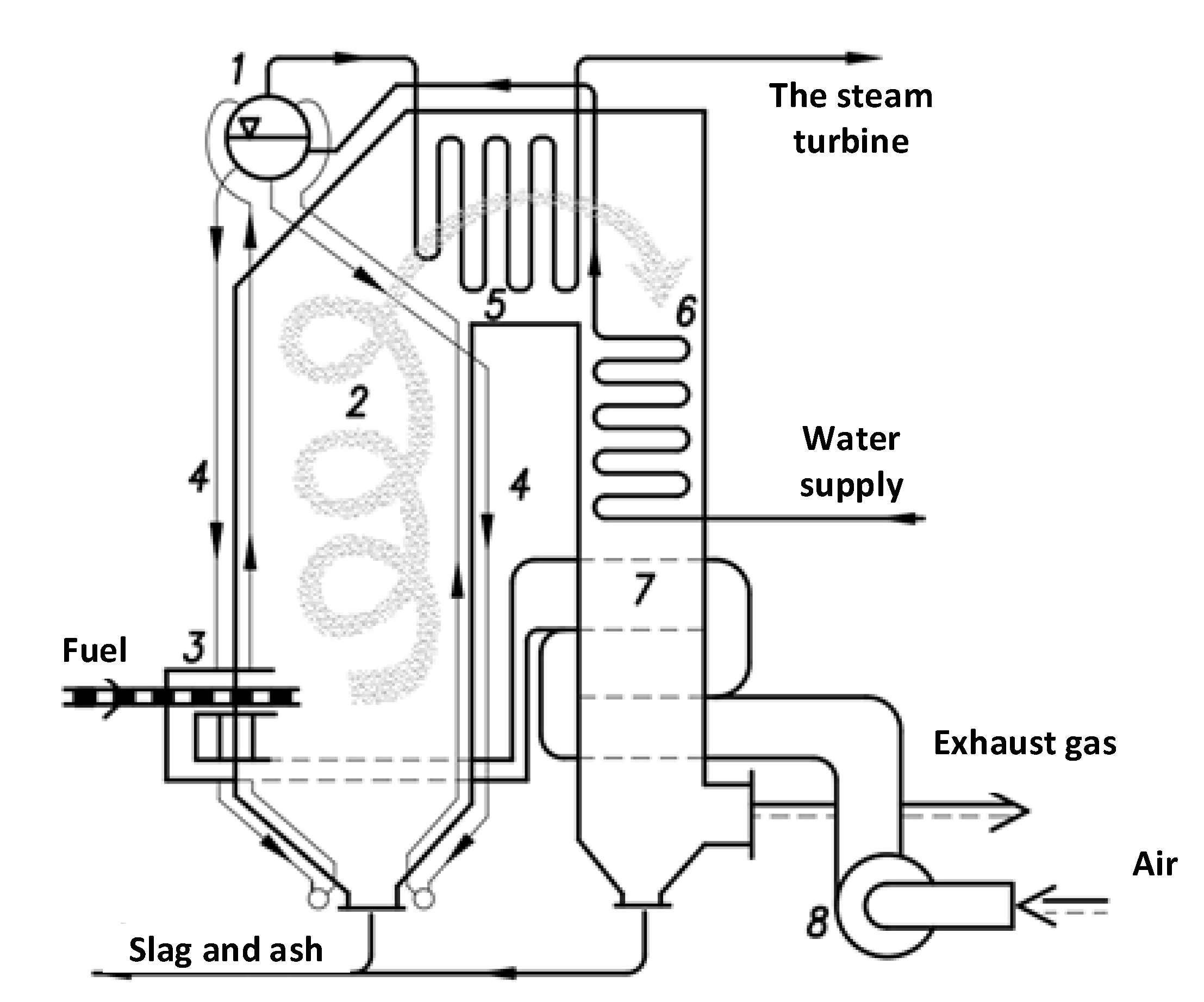
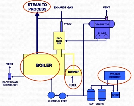
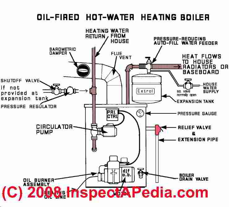
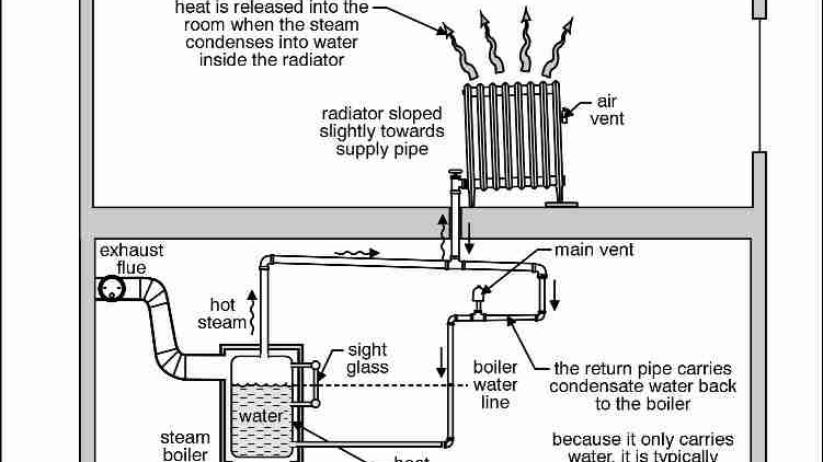
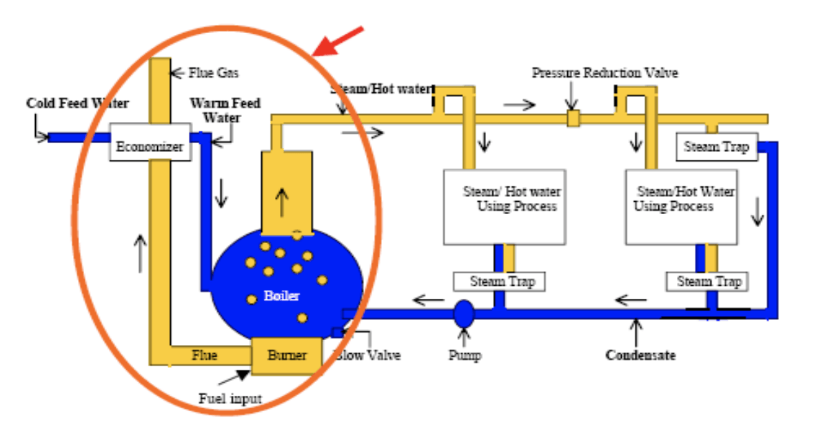
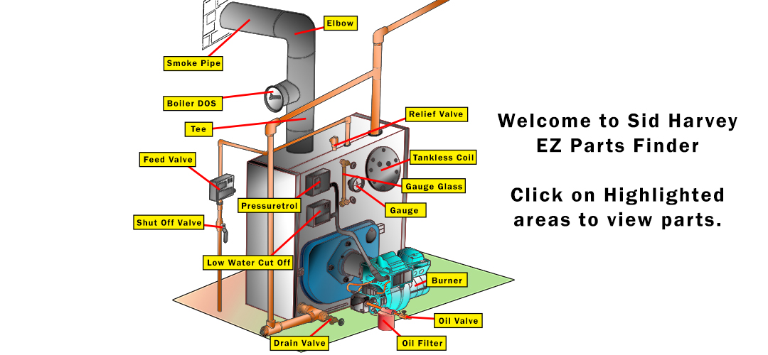
Steam Boiler Diagram With Parts for Dummy's. Below is a typical steam boiler diagram for dummy's to understand with name of each component or boiler part. First of all you should understand that there are many types and nomenclature of boilers. For example steam boiler, combi boiler, vaillant boiler, hot water boiler, gas boiler, electric.

Residential steam boiler piping diagram
Dan Holohan explains best practices for how to pipe a steam heating boiler. Learn more at www.heatinghelp .Want to be an expert? Read Dan Holohan's book T... Residential steam boiler piping diagram Continue. Internal water pipes. Link to Pg 6 Chart installation install 1/2 male adapters in both KEYSTOKER STEAM BOILER INSTALLATIONS INSTRUCTION 4 90,000 BTU - 105,000 BTU's. Bring full source water and steam boilers - Series 2 88. Connect the water boiler pipeline 14 Connect the steam boiler piping... Design of Boilers and Power Piping Section I PG‐58.3 Boiler External Piping • The Code Jurisdictional Limits of the boiler external piping systems are shown in Figure PG‐58.3.1. • The materials, design, fabrication, installation and testing shall be in accordance with B31.1, Power Piping.
Residential steam boiler piping diagram. System Diagrams Radiant Heat Multi Zone In-Floor 71 73 75 80 86 102 76 67 65 Forced Air vs. Radiant In-Floor Insulation Closed-cell Polystyrene Thermal Insulation OUT IN Greenhouse Heating Options Radiant PEX piping under the table Forced Air Return Supply When using mesh style tables - PEX piping must be protected from UV rays. 4 mil. black. Design of Boilers and Power Piping Section I PG‐58.3 Boiler External Piping • The Code Jurisdictional Limits of the boiler external piping systems are shown in Figure PG‐58.3.1. • The materials, design, fabrication, installation and testing shall be in accordance with B31.1, Power Piping. Piping diagrams figure 6. The heating boiler piping diagram at page top courtesy of raypak shows the heating system circulator pump assembly red in our sketch on the return or inlet side of the heating boiler. Application type diagram see installation manual for complete instructions. Bradford White is an American company with its manufacturing facilities located in the United States of America. Products made by Bradford White are manufactured in the United States using the finest raw materials and components from around the world to deliver the highest quality and value to our customers.
A "one-pipe system," or "Monoflo system," as it is sometimes called, is a distribution system that uses specialized tee fittings to divert a portion of the hot water through a branch piping path. If a manual or automatic control valve is placed in the branch piping path, the water flow through a given heat emitter can be fully controlled. Piping Diagram - Series 64™ Near Boiler Piping Diagram - 64-09 through 64-12. 13. Wire the tank or system/pipe sensor connected to the DHW sensor terminals on the follower boiler addressed as #1. 14. The system/pipe sensor must be placed on common piping to the tank, as close to the tank as possible. 15. The system/pipe sensor is wired to the system sensor terminals on the master boiler. Diagram Geothermal Piping Diagrams Full Version Hd Quality Nudiagrams Cxlecce2021 It. Burnham 206pvni T2 164 000 Btu Water Boiler 82 Efficiency Electronic Ignition Natural Gas Lp Power Vented. Burnham steam boiler wiring diagram mst629 user manual parts mr full megasteam oil fired u s crown bsi ms 40 indirect new gas pipping help heating.
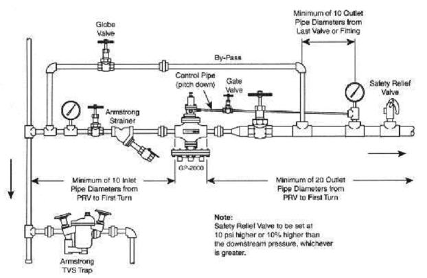
The correct way to install a PRV is shown in the above diagram. There must be a minimum distance between the PRV and sensing point, and the control line must slope down to the pipe - NOT the PRV, so that condensate will drain back to the steam line where it will be removed by a steam trap. The expansion tank must be properly. As drawn in the diagram, to charge the tank from the primary loop. 2. tanks ( where the hot water enters) and going to the Burnham boiler. ma servicing a gas steam boiler burnham piping diagram furnace ac and plumbing repair in. burnham steam boiler gas manual. steam boiler wiring diagram. The primary component of a Hartford loop diagram is the location of a Hartford loop top and its distance from the boiler water top. Standard Hartford loop diagrams generally place the top of the loop 2 inches below the steam boiler's water line. hartford loop steam piping diagram is among the photos we discovered on the net from reputable sources. What You Need to Know About Residential Steam Boilers - The Spruce. May 18, 2017 - Unlike hot water boilers which rely upon a pump to circulate the hot water, steam boilers use this pressure to move the steam through the piping. PROCESS FLOW DIAGRAM STEAM AND CONDENSATE. PIPING AND INSTRUMENTATION DIAGRAM BOILER NO. 1. PIPING AND.
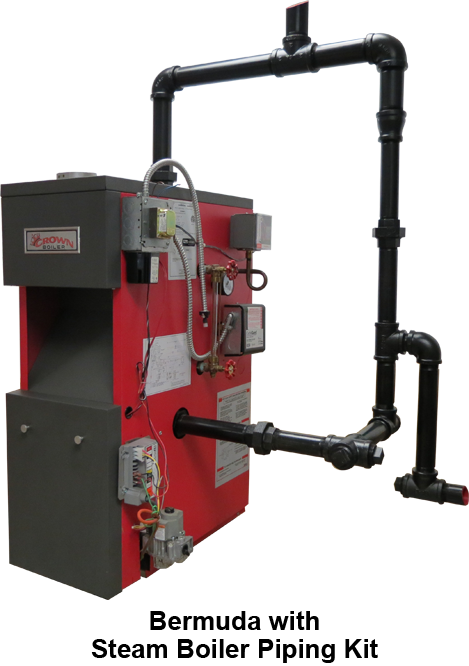
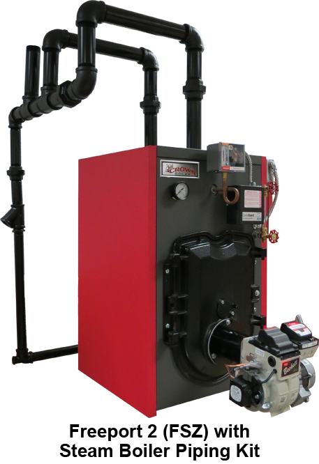
The Velocity Boiler Works Steam Boiler Piping Kit is a more convenient way to pipe steam boilers during an installation. The kits work with both oil and gas models and are available for the Bermuda, Kingston, and Freeport 2 FSZ boilers.. Kitted to allow you to pipe the near boiler piping as recommended in the manual, this will guarantee you go to the job prepared and won't waste time making.
1221. (Indoor) Installation / Operation Instruction Manual. 1258. (Indoor) Spec Sheet. Pump Mounted 5088-11. (080 & 105) Pump Mounted 5088-12.
Raypak Pool & Spa, Residential and Commercial Hydronic Products -
Standard Steam Boiler Plant Piping Diagram Author: Department of Veterans Affairs, Office of Construction and Facilities Management, Facilities Standards Service Subject: Standard Details Created Date: 10/7/2020 2:22:24 PM
Dan Holohan explains best practices for how to pipe a steam heating boiler. Learn more at www.heatinghelp .Want to be an expert? Read Dan Holohan's book T...
The Hartford Loop: this article gives a defnition of the Hartford Loop used on steam heating systems, explains why the Hartford Loop is necessary to protect against steam boiler damage, and gives a bit of the history of the development of the Hartford loop. We include sketches and photographs of the Hartford Loop piping arrangement on steam boilers and list inspection & defect points of interest.
Residential steam boiler piping diagram Continue. Internal water pipes. Link to Pg 6 Chart installation install 1/2 male adapters in both KEYSTOKER STEAM BOILER INSTALLATIONS INSTRUCTION 4 90,000 BTU - 105,000 BTU's. Bring full source water and steam boilers - Series 2 88. Connect the water boiler pipeline 14 Connect the steam boiler piping...
WIRING DIAGRAMS. Most of the wiring diagrams are for natural gas powered steam boilers. Wiring diagrams for oil burning and water boilers are noted. CT 6, 10, 15 and 25 boiler wiring diagram. CT 6 and 25 boiler wiring diagram. CT 35 and 50 boiler wiring diagram. HRT 20 and 30 boiler wiring diagram. Keystone series boiler wiring diagram.
7 Comments. on Burnham Steam Boiler Piping Diagram. Burner/boiler systems produce steam or hot water in a pressurized vessel by mixing extremely flammable gaseous, liquid covered by Burnham's standard warranty. fiG. 10.. recommended boiler piping diagrams in this manual. b. attach. My Burnham boiler rusted out and has a hole after only 8 years.
Bruce M. Member Posts: 143. December 2004. in THE MAIN WALL. If you go to the Burnham web site and look at the piping diagrams there is a link to type "Viewers" that are needed in order to see the diagrams. One viewer is "Whip" and the other is "Volo". Neither of these links point to a currently available viewer.
performance of a replacement steam boiler and should always be considered as part of the boiler installation. Always be sure to include clean-out and skimming tees in the near boiler piping. These "Tees" are necessary for proper cleaning and servicing of the boiler. • For further piping information refer to the I=B=R
The steam boiler is an old convection heating technology dating back over 200 years and is most commonly found in old homes. Because steam boilers operate at a higher temperature than hot-water boilers, they are inherently less efficient than their hot-water cousins and are more finicky to operate.
application type diagram see installation manual for complete instructions. install in accordance with all local codes. typical piping for conventional single boiler installation lb-500, lb-750, lb-1000 • safety relief valve setting should not exceed pressure rating of any component in the system. • piping should conform to local codes.
2019 Okt 27 - Explore Steam Boiler Board's board "Steam Boiler Diagram", followed by 428 people on Pinterest. See more ideas about uap.
The near boiler piping is the first line of defense for a reliable system. a) Correctly installed, the near boiler piping acts as a. Steam Boiler fires. Water boils in boiler, creating steam. Surface level rises slightly because the steam bubbles displace water.














0 Response to "43 Residential Steam Boiler Piping Diagram"
Post a Comment