40 Collaboration Diagram In Uml
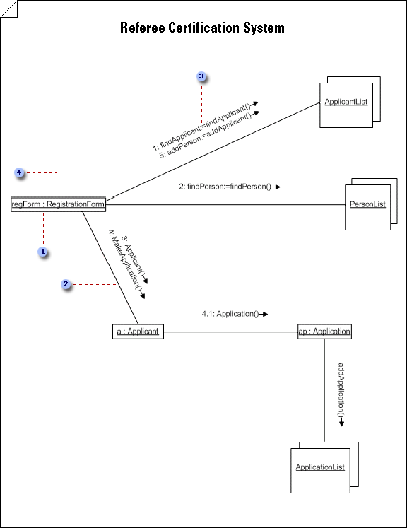
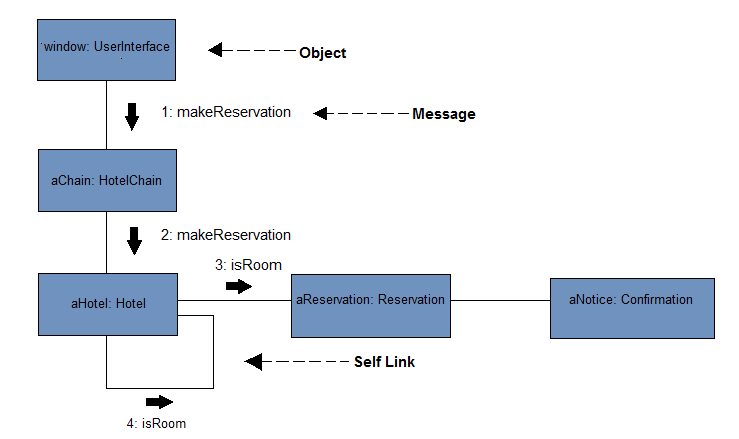
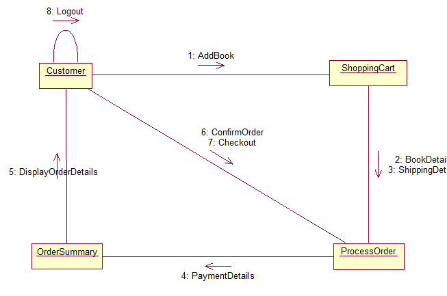
An Instance-Level UML Collaboration diagram. Use Instance-Level Diagrams To Explore Object Design Issues. Instance-level UML Collaboration diagrams, such as the one shown in Figure 1, depict interactions between objects (instances). Instance-level diagrams are typically created to explore the internal design of object-oriented software. UML - Sequence and collaboration diagram on ATM transactionWatch more Videos at https://www.tutorialspoint /videotutorials/index.htmLecture By: Mr. Arnab.
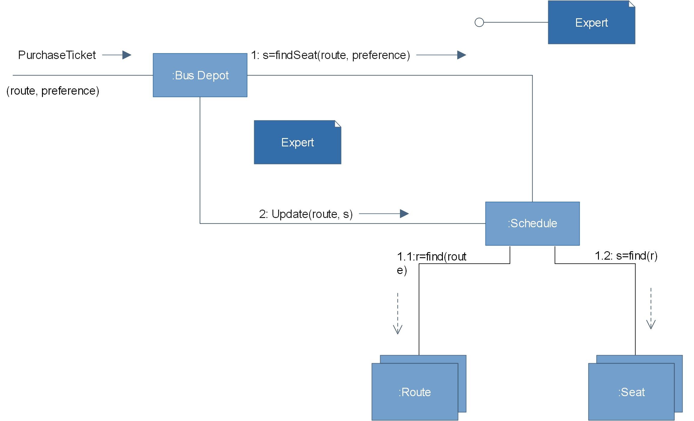
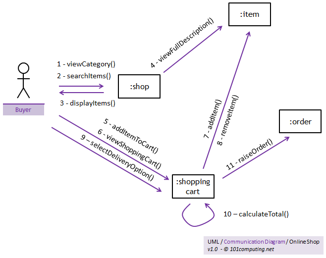
Collaboration diagrams ( known as Communication Diagram in UML 2.x) are used to show how objects interact to perform the behavior of a particular use case, or a part of a use case. Along with sequence diagrams, collaboration are used by designers to define and clarify the roles of the objects that perform a particular flow of events of a use case.

Collaboration diagram in uml
A collaboration diagram, also known as a communication diagram, is an illustration of the relationships and interactions among software objects in the Unified Modeling Language (UML). These diagrams can be used to portray the dynamic behavior of a particular use case and define the role of each object. UML Collaboration Diagrams Use a collaboration diagram (collaboration diagram: An interaction diagram that shows, for one system event described by one use case, how a group of objects collaborates with each other.) to show relationships among object roles such as the set of messages exchanged among the objects to achieve an operation or result.. UML Collaboration diagrams (interaction. Collaboration diagram yang jelas adalah bagian dari UML (unified modeling language), bagi kalian yang belum mengenal apa itu UML, dapat membaca tulisan saya sebelumnya terkait pengertian dan definisi UML lengkap.. Collaboration diagram dikenal dengan beberapa nama, seperti communication diagram dan interaction diagram, yang mana penggambaran interaksi dan hubungan antara objek dalam software.
Collaboration diagram in uml. UML collaboration diagrams are great tools for documenting the flow of messages between objects while providing a unique perspective?a view of the relationships between collaborating objects. At the very heart of any complex software application are business objects. As the user interacts with the software, business objects respond by carrying. A Sequence diagram is an interaction diagram that details about the operation that is carried out. The sequence diagram captures the interaction between the objects in the context of collaboration. Sequence diagrams are time focused and they show the order of the interaction visually by using the vertical axis of the diagram to represent time. Important: The UML Collaboration diagram is not available in Visio 2013 and newer versions. For information on UML diagrams in Visio 2013 and newer versions, see UML diagrams in Visio. In a Classifier Role shape, the object's designator string is underlined to indicate that the object is an instance. UML Distilled by Martin Folwler Chapter 5,6,7 presented by Robert Jakubov Interaction Diagrams: Sequence and Collaboration Diagrams. q Both specify the same information.. q Both explore the interaction among objects within a single problem domain.. q However, each emphasizes different aspects.. Sequence diagram is temporally-oriented
UML Collaboration Diagrams Use a collaboration diagram (collaboration diagram: An interaction diagram that shows, for one system event described by one use case, how a group of objects collaborates with each other.) to show relationships among object roles such as the set of messages exchanged among the objects to achieve an operation or result.. UML Collaboration diagrams (interaction. Collaboration Diagram is also called as the Communication Diagram. In collaboration diagram we show the different objects, how they are organized and what ar... UML Collaboration Diagram depicts the interactions between objects or parts in terms of sequenced messages and describes both the static structure and dynamic behavior of a system. ConceptDraw helps you to start designing your own UML Collaboration Diagrams with examples and templates. You can use the appropriate stencils of UML notation for. The Collaboration Diagram in UML is also called as a communication diagram. The purpose of a collaboration diagram is to emphasize structural aspects of a system, i.e., how various lifelines in the system connects. Timing diagrams focus on the instance at which a message is sent from one object to another object.
Activity Diagram (UML) Administration & Security; Amazon Web Services; Analytics; Android Mockups; Application Services; Block Diagram; Business Process Management; Chemical Chart; Cisco Network Diagram; Class Diagram (UML) Collaboration Diagram (UML) Compare & Contrast Diagram; Component Diagram (UML) Compute & Networking Communication Diagram - A Communication Diagram(known as Collaboration Diagram in UML 1.x) is used to show sequenced messages exchanged between objects. A communication diagram focuses primarily on objects and their relationships. We can represent similar information using Sequence diagrams,however, communication diagrams represent objects. Collaboration diagrams (known as Communication Diagram in UML 2.x) are used to show how objects interact to perform the behavior of a particular use case, or a part of a use case.Along with sequence diagrams, collaboration are used by designers to define and clarify the roles of the objects that perform a particular flow of events of a use case. UML Collaboration Diagram depicts the interactions between objects or parts in terms of sequenced messages and describes both the static structure and dynamic behavior of a system. Rapid UML solution provides templates, examples and libraries of stencils for quick and easy drawing all the types of system and software engineering diagrams according to UML 2.4 and 1.2 notations.
UML Collaboration. Collaboration extends both behaviored classifier and structured classifier to explain how a collection of cooperating instances achieve a joint task or set of tasks. Its primary purpose is to explain how a system works and, therefore, it typically only incorporates those aspects of reality that are deemed relevant to the explanation.
Collaboration diagram yang jelas adalah bagian dari UML (unified modeling language), bagi kalian yang belum mengenal apa itu UML, dapat membaca tulisan saya sebelumnya terkait pengertian dan definisi UML lengkap.. Collaboration diagram dikenal dengan beberapa nama, seperti communication diagram dan interaction diagram, yang mana penggambaran interaksi dan hubungan antara objek dalam software.
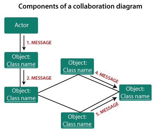
UML Collaboration Diagram. The collaboration diagram is used to show the relationship between the objects in a system. Both the sequence and the collaboration diagrams represent the same information but differently. Instead of showing the flow of messages, it depicts the architecture of the object residing in the system as it is based on object.
In the last article, we saw what Sequence diagrams are, the notations to be used in Sequence diagrams, their significance, and how to make a Sequence diagram using Poseidon.We then made a Sequence diagram for our Courseware Management System. The next in the dynamic diagrams in UML that we will cover is the Collaboration Diagram.
UML - Basic Notations. UML is popular for its diagrammatic notations. We all know that UML is for visualizing, specifying, constructing and documenting the components of software and non-software systems. Hence, visualization is the most important part which needs to be understood and remembered. UML notations are the most important elements in.
The UML collaboration diagram can be illustrated by designing objects in a structure and illustrating the connections between the objects as links. Given below is a step-by-step guide to creating a collaboration diagram with Edraw Max. Step 1: Open a UML Diagram template. Click on new, select Software and then pick UML Model Diagram..
Collaboration diagram- UML diagram 1. Duration: 3hrs 1 Ramakant Soni Assistant Professor Dept. of Computer Science B K Birla Institute of Engineering & Technology, Pilani, India Ramakant Soni @ BKBIET Pilani 2. Collaboration Diagram Definition Collaboration Diagrams captures dynamic behavior of the objects in the system (message-oriented)..
The collaboration diagram and sequence diagram shows similar information but in a distinct form. It can portray the architecture of an object inside the system. It can be used to depict the relationship among various objects within the system.
Communication diagrams, formerly known as collaboration diagrams, are almost identical to sequence diagrams in UML, but they focus more on the relationships of objects—how they associate and connect through messages in a sequence rather than interactions.
Collaboration Diagram [classic] Use Creately's easy online diagram editor to edit this diagram, collaborate with others and export results to multiple image formats. You can edit this template and create your own diagram. Creately diagrams can be exported and added to Word, PPT (powerpoint), Excel, Visio or any other document.
We have two types of interaction diagrams in UML. One is the sequence diagram and the other is the collaboration diagram. The sequence diagram captures the time sequence of the message flow from one object to another and the collaboration diagram describes the organization of objects in a system taking part in the message flow.
A Collaboration diagram is very similar to a Sequence diagram in the purpose it achieves; in other words, it shows the dynamic interaction of the objects in a system. A distinguishing feature of a Collaboration diagram is that it shows the objects and their association with other objects in the system apart from how they interact with each other.
2: Add UML Collaboration Diagram Shapes Drag and drop shapes from the "UML Collaboration Diagram" library on the left. Click here for more information about UML collaboration diagram shapes and symbols.Rulers and connecting dots will automatically appear on the shapes, all you need to do is to adjust the position and Edraw will tell you whether it is in the right position or not.
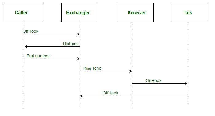
You often create a sequence diagram to model the logic of a use case. In this case a frame with the label alt is used along. A uml sequence diagram shows how messages go back and forth between. To build a sequence diagram, use a uml sequence template or starter diagram,. Q collaboration diagrams demonstrate how objects are .
A collaboration diagram, also known as a communication diagram, is an illustration of the relationships and interactions among software objects in the Unified Modeling Language (UML). These diagrams can be used to portray the dynamic behavior of a particular use case and define the role of each object.
In many ways, a communication diagram is a simplified version of a collaboration diagram introduced in UML 2.0. State Diagram Statechart diagrams , now known as state machine diagrams and state diagrams describe the dynamic behavior of a system in response to external stimuli.












0 Response to "40 Collaboration Diagram In Uml"
Post a Comment