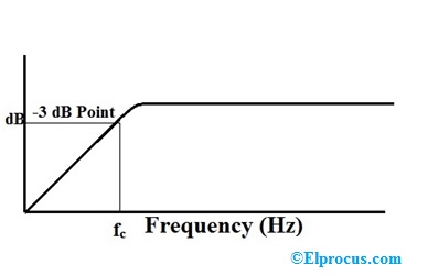
43 High Pass Filter Diagram
An RL high pass filter is a filter circuit, composed of a resistor and an inductor, which passes high-frequency signals and blocks low frequency signals. When an resistor is placed in series with the power source of the circuit and an inductor is placed in parallel to that same power source, as shown in the diagram circuit above, this type of. pass, or high-pass response. For ex-ample, ab 11== 0 leads to a low-pass filter (LPF), the focus of our study here. To realize higher-order filters, biquad sections can be cascaded. The Need for Complex Poles We typically begin the design of filters by deciding on the order and shape of
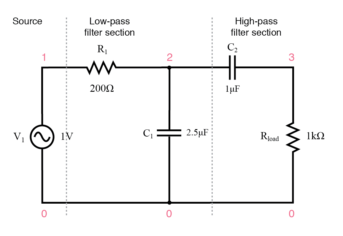
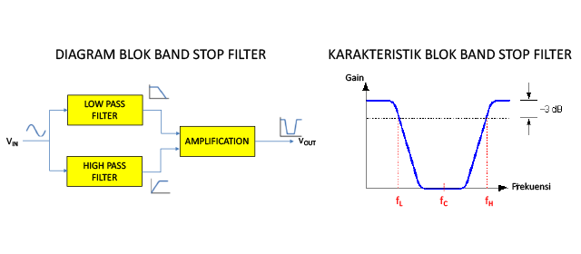
Filter circuits can be designed to accomplish this task by combining the properties of low-pass and high-pass into a single filter. The result is called a band-pass filter. Creating a bandpass filter from a low-pass and high-pass filter can be illustrated using block diagrams: System level block diagram of a band-pass filter.
High pass filter diagram
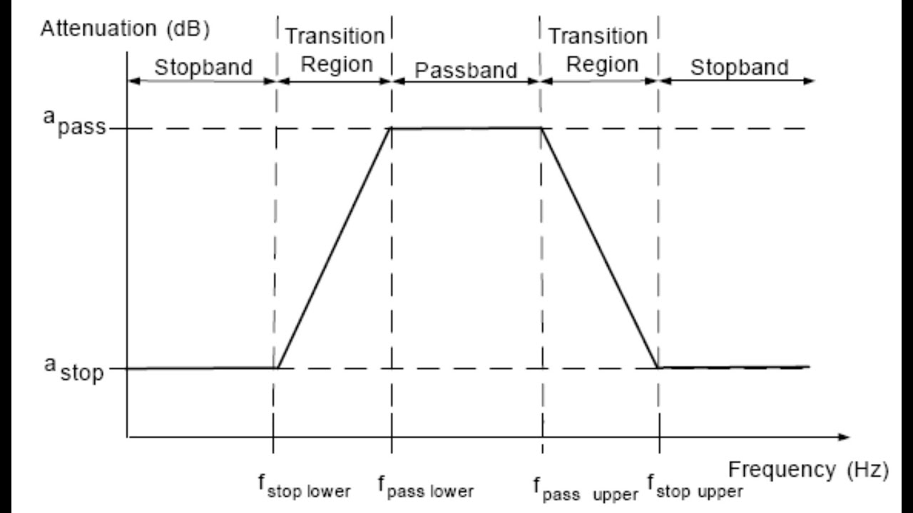
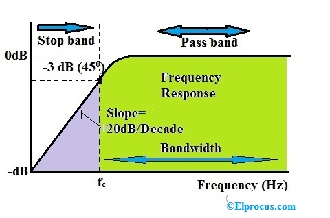
A high-pass filter (HPF) is an electronic filter that passes signals with a frequency higher than a certain cutoff frequency and attenuates signals with frequencies lower than the cutoff frequency. The amount of attenuation for each frequency depends on the filter design. A high-pass filter is usually modeled as a linear time-invariant system.It is sometimes called a low-cut filter or bass-cut. Feb 22, 2020 · The active band pass filter is a cascading connection of high pass and low pass filter with the amplifying component as shown in the below figure. Block Diagram of Active Band Pass Filter. The circuit diagram of Active Band Pass Filter is divided into three parts. The first part is for a high pass filter. Then the op-amp is used for the. 1) Pass band frequency: Frequencies that are allowed through the filter without/low attenuation are called passband frequencies. 2) Stop band frequency: Frequencies that are completely blocked faces high attenuation are called stopband frequencies. 3) Bandwidth: It is the range of particular frequencies Cutoff frequency (higher cutoff frequency/ lower cutoff frequency): The frequency at which.
High pass filter diagram. A high-pass filter (HPF) is an electronic filter that passes signals with a frequency higher than a certain cutoff frequency and attenuates signals with frequencies lower than the cutoff frequency. The amount of attenuation for each frequency depends on the filter design. A high-pass filter is usually modeled as a linear time-invariant system.It is sometimes called a low-cut filter or bass-cut. A sample circuit diagram of a simple passive Bandpass filter is shown below. The first half of the circuit is a High-Pass filter which filters the low frequencies and allows only the frequency that is higher than the set high cut-off frequency (fcHIGH). The value of this high cut-off frequency can be calculated using the formulae. Block diagrams may also be helpful in representing and understanding filter circuits. Consider these symbols, for instance: Which of these represents a low-pass filter, and which represents a high-pass filter? Explain your reasoning. Also, identify the new filter functions created by the compounding of low- and high-pass filter "blocks": Thus, the Active Low Pass Filter has a constant gain A F from 0Hz to the high frequency cut-off point, ƒ C.At ƒ C the gain is 0.707A F, and after ƒ C it decreases at a constant rate as the frequency increases. That is, when the frequency is increased tenfold (one decade), the voltage gain is divided by 10. In other words, the gain decreases 20dB (= 20*log(10)) each time the frequency is.
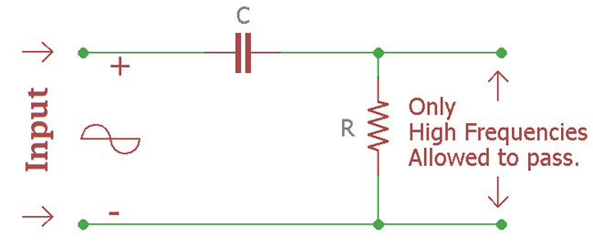
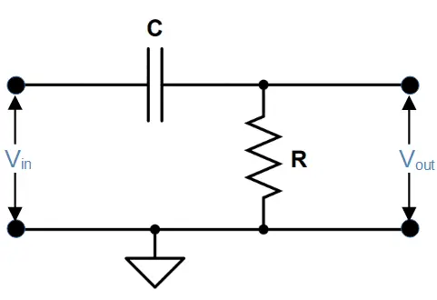
The picture goes on to explain where the pole zero diagram comes from and how you can relate natural resonant frequency (\$\omega_n\$) with zeta (\$\zeta\$). For your reference, zeta = 1/2Q. You will also find that the shape of the curve reverses (with a hump) for 2nd order high pass filters: - The high-pass filter picture came from here. Figure 2-2 - Ideal magnitude responses of (a.) low-pass, (b.) high-pass, (c.) bandpass, and (d.) bandstop filter. The second category of ideal filter is the high-pass filter and has a gain of 0 from 0 to ωT and a gain of 1 for all frequencies greater than or equal to ωT. The ideal high-pass filter is shown in Fig. 2-2b. High Pass Filter Circuit Diagram The characteristics of the high pass filter comes from the interplay of capacitive reactance and resistance, which both contribute to the total impedance. The impedance contributed by the resistor (i.e. resistance) doesn’t depend on the frequency, but the capacitive reactance is inversely proportional to the. A high pass filter composed of a resistor and a capacitor is called a high pass RC filter. And a high pass filter with a resistor and an inductor is called a high pass RL filter. We will go through both of these type of circuits on this page and show how both RC and LC high pass filters are constructed. Both circuits have the effect of passing.
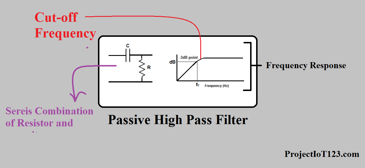
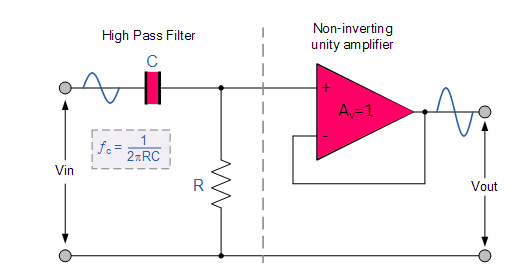
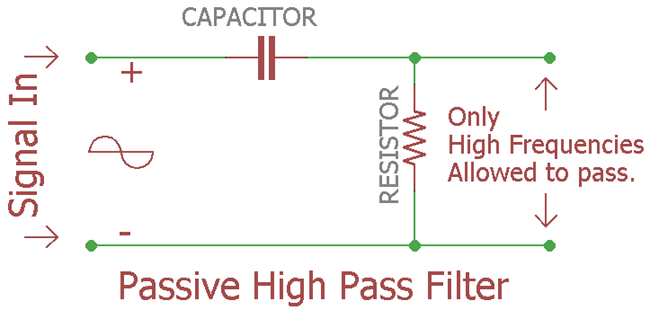
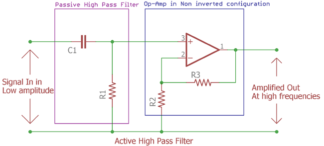
Previously we discussed Passive Low Pass Filter, now it is the time to look insight of passive high pass filter.. Same as like before, if you look into the name it shows "Passive", "High", "Pass" and "Filter". So, as the name suggests, it is a filter that will block Low frequencies, but pass the high frequency above the predetermined value, which will be calculated by the formula. An all-pass filter is a signal processing filter that passes all frequencies equally in gain, but changes the phase relationship among various frequencies. Most types of filter reduce the amplitude (i.e. the magnitude) of the signal applied to it for some values of frequency, whereas the all-pass filter allows all frequencies through without changes in level. Active High Pass Filter Circuit Diagram. It consists of a passive filter section followed by a non-inverting operational amplifier. The frequency response of the circuit is the same as that of the passive filter, except that the amplitude of the signal is increased by the gain of the amplifier. A high pass filter (also known as a low-cut filter or bass-cut filter) is an electronic filter that permits signals with a frequency higher than a certain cutoff frequency and attenuates signals with frequencies lower than that cutoff frequency. The inverse of a high-pass filter is a low-pass filter, which allows signals with frequencies lower.
High Pass Filter Electronics Reference
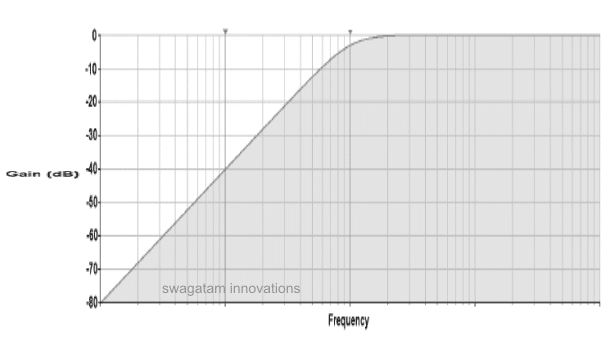
12+ High Pass Filter Diagram. At high frequencies, c has very low impedance, and the signal passes through unhindered. This is a diagram below showing what happens to low and high frequencies when fed into this high pass filter The actual amount of attenuation for each frequency varies from filter to filter and depends on the size of the.
Analog Band Pass Filter And Simulation In Multisim Part 1 2
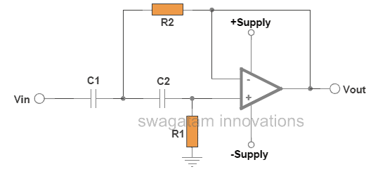
The above circuit uses two first-order filters connected or cascaded together to form a second-order or two-pole high pass network. Then a first-order filter stage can be converted into a second-order type by simply using an additional RC network, the same as for the 2 nd-order low pass filter.The resulting second-order high pass filter circuit will have a slope of 40dB/decade (12dB/octave).
High Pass Filter Definition Circuit Characteristics And
High Pass Filter Calculator Electronicbase. Second Order High Pass Erworth Filter Derivation. The Schematic Of Second Order En Key High Pass Active Filter Scientific Diagram. High Pass Filter Calculator. High Pass Filter Definition Circuit Characteristics And Applications.
High Pass Filter Definition Circuit Characteristics And
An audio pass filter attenuates an entire range of frequencies. There are two types of pass filters (Fig. 1). A high-pass filter (HPF) attenuates content below a cutoff frequency, allowing higher frequencies to pass through the filter. A low-pass filter (LPF) attenuates content above a cutoff frequency, allowing lower frequencies to pass.

High Pass Filter Passive Rc Filter Tutorial
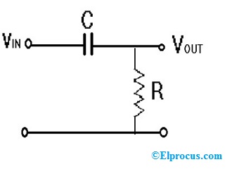
The circuit diagram of the high pass filter using op-amp is shown below. The passive RC HPF is connected to the non-inverting op-amp for amplification and voltage gain control. High Pass Filter using Op-Amp. The output is limited by the open-loop characteristics of the op-amp.
Passive High Pass Filter
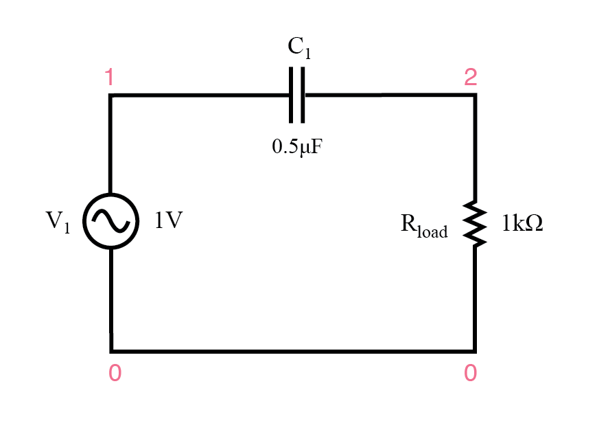
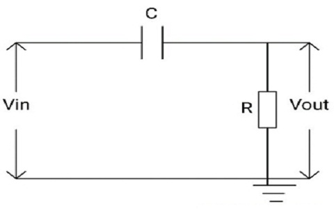
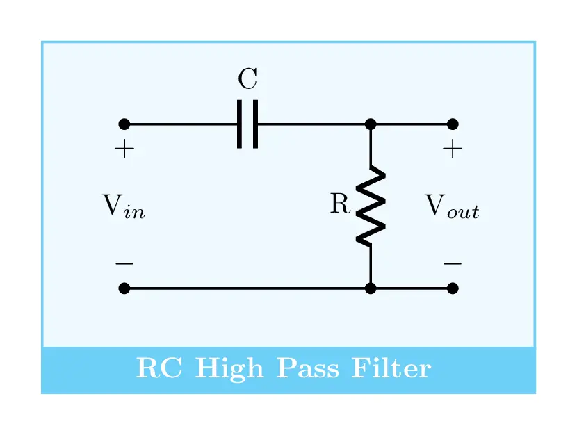
The basic High Pass Filter is built by a series connection of capacitor and resistor. While the input signal is applied to the capacitor, the output is drawn across the resistor. High Pass Filter Circuit. In this circuit arrangement, the capacitor has high reactance at lower frequencies so it acts as an open circuit to the low-frequency input.

Second Order High Pass Butterworth Filter Eeeguide Com
A high pass filter will allow the frequencies which are higher than the cut-off frequency and attenuate the frequencies lower than the cut off frequency. In some cases, this filter is also termed as 'Low-Cut' filter or 'Base-cut' filter. The amount of attenuation or the pass band range will depend on the designing parameters of the filter.

Low And High Pass Filter Circuit Electronic Circuit
Passive High Pass Filter. Order The High Pass Crossover 100 Hz 8 Ohm Soundimports. Passive High Pass Filter. Dayton Audio 3 5k Hpf 8 Speaker High Pass Filter 3500hz 12db Octave Ohm Audiophonics. Composite High Pass Filter Passive श क ष ट र नर In Tharapm Chennai Ohm Technologiees Id 3894115588. Passive Filter Design.

High Pass Filters Developer Help
low pass filters and CR high pass filters are also used in speaker systems to route appropriate bands of frequencies to different designs of speakers (i.e. ´ Woofers´ for low frequency, and ´Tweeters´ for high frequency reproduction). In this application the combination of high and low pass filters is called a "crossover filter".

Jobsheet Praktikum 8 High Pass Filter Pdf Download Gratis
Feb 22, 2020 · The active band pass filter is a cascading connection of high pass and low pass filter with the amplifying component as shown in the below figure. Block Diagram of Active Band Pass Filter. The circuit diagram of Active Band Pass Filter is divided into three parts. The first part is for a high pass filter. Then the op-amp is used for the.

High Pass Filter Wikipedia
High-Pass Filters Working. The opposite to the low-pass filter is the high-pass filter. High-pass filters pass chosen high-frequency current and reject low-frequency currents. The filter circuit includes a capacitor in series with the incoming signal voltage and an inductance shunt across the line, Figure 6.
High Pass Filters Filters Electronics Textbook
1) Pass band frequency: Frequencies that are allowed through the filter without/low attenuation are called passband frequencies. 2) Stop band frequency: Frequencies that are completely blocked faces high attenuation are called stopband frequencies. 3) Bandwidth: It is the range of particular frequencies Cutoff frequency (higher cutoff frequency/ lower cutoff frequency): The frequency at which.

20hz To 200hz Variable High Pass Filter
-High pass filter •Passes high frequencies, attenuates low frequencies -Band pass filter •Attenuates high and low frequencies, lets middle frequencies pass. M. Horowitz, J. Plummer, R. Howe 11 RC Low Pass Filters v in v out C=0.1 µF • Let's think about this before we do any math
Pengertian High Pass Filter Hpf Atau Tapis Lolos Atas
Active Band Pass Filter Circuit. This cascading together of a low and a high pass passive filters produces a low “Q-factor” type filter circuit which has a wide pass band. The first stage of the filter will be the high pass stage that uses the capacitor to block any DC biasing from the source.

High Pass Filter Passive Rc Filter Tutorial
A low-pass filter is a filter that passes signals with a frequency lower than a selected cutoff frequency and attenuates signals with frequencies higher than the cutoff frequency. The exact frequency response of the filter depends on the filter design.The filter is sometimes called a high-cut filter, or treble-cut filter in audio applications. A low-pass filter is the complement of a high-pass.

High Pass Filters Developer Help
Show the circuit diagram of a high and Low pass RC filter. Write an expression for the eout in each case, and explain how the low pass and high pass filter response to high and low frequency signals. Show a qualitative plot of the frequency response curve V-f both for the low pass and high

Low And High Pass Filter Circuit High Pass Circuit
RC High-pass Filter Design Tool. This page is a web application that design a RC high-pass filter. Use this utility to simulate the Transfer Function for filters at a given frequency or values of R and C. The response of the filter is displayed on graphs, showing Bode diagram, Nyquist diagram, Impulse response and Step response.

Passband Band Pass Filter Baseband Signal Low Pass Filter
The MFB filters are very commonly used in circuits due to the fact that they provide reasonable performance with the simplest circuit. They can be designed to obtain narrow bandwidth and high gain. They are suitable for the design of Band Pass filters since the bandwidth, mid-band frequency can be easily adjusted or varied. These circuits has an amplifier with more than one feedback and hence.
High Pass Filter Circuit Characteristics And Its Applications
High Pass Filter. The circuit diagram of the high pass filter is shown below. An HPF blocks the low-frequency signals & allows just high-frequency signals for flowing through it. Even though it provides reduction to high-frequency signal also however the attenuation issue is so little that it can be ignored.

Low And High Pass Filter Circuit High Pass Circuit
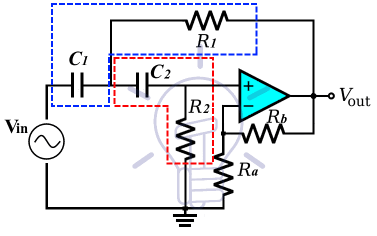
High Pass, Low Pass and band Pass from a Single Circuit A state variable filter such as the one shown below can generate three outputs: high pass, band-pass, and low pass. This is therefore an extremely flexible filter design, specially if the resonant frequency is featured to be adjustable.

High Pass Filter Hpf Filter Pasif Belajar Elektronika

High Pass Filter Audio Penjelasan Karakteristik Carakerja
Types Of Active High Pass Filter 1st Amp 2nd Order High Pass
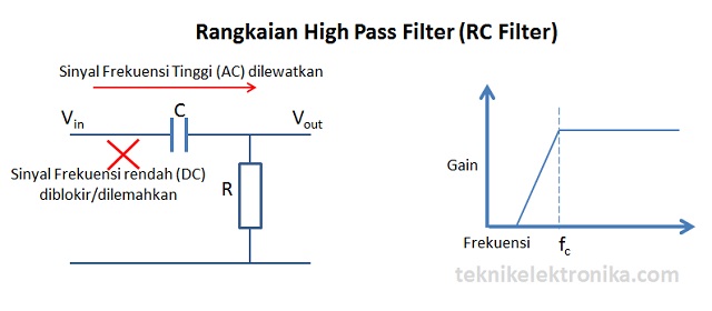
Pengertian High Pass Filter Hpf Atau Tapis Lolos Atas
Rc High Pass Filter Circuit In Tikz Circuitikz Tikzblog
Operational Amplifier Active High Pass Filter Projectiot123

Filter Low Pass Filter Elektronik Sirkuit Elektronik Filter
Active High Pass Filter Circuit Diagram And Operation
High Pass Filter Definition Circuit Characteristics And

High Pass Filter Auto Entuzijasta Hrvatska
Passive High Pass Filter

Band Pass Filter Bpf Rc
How To Design A High Pass And Low Pass Filter Circuits

Equivalent Circuit Of Passive High Pass Filter Download

High Pass Filter
Band Pass Filters Filters Electronics Textbook
Active High Pass Filter
How To Design A High Pass And Low Pass Filter Circuits

6 High Pass Filter Of Nth Order A Bode Plot A Amplitude
Pengertian Band Stop Filter Bsf Atau Notch Filter Teknik

High Pass Filter Types Applications Advantages


Filter Aktif High Pass Hpf
0 Response to "43 High Pass Filter Diagram"
Post a Comment