42 Septic Tank Electrical Wiring Diagram
Septic tank electrical wiring diagram. Once the box is in place the cable can be wired into the breaker box. Assortment of septic pump wiring diagram. I have a 122 coming from the house along with a 142 which i believe is the alarm wire. Site Evaluation Diagram - Appendix A - Attach a detailed site diagram including the system The sewage system includes a septic tank and treatment mound. The Wisconsin mound wastewater soil treatment system was developed in the s Schematic of the Wisconsin mound system showing septic tank, dosing.
How to wire a septic pump.
Septic tank electrical wiring diagram
Plumb the outlet of the septic tank into the inlet on the OxyPro. Plumb the outlet of the OxyPro (4-inch DWV, or 2-inch sched. 40) to the drain field. Run the provided 1-inch waste line from the treatment tank into a side inlet on the septic tank, using the provided adapter. The CATV pipe can be glued using normal PVC primer and cement. Variety of aerobic septic system wiring diagram. A wiring diagram is a simplified standard pictorial representation of an electrical circuit. It reveals the parts of the circuit as streamlined forms, as well as the power as well as signal connections between the gadgets. Collection of septic tank float switch wiring diagram. A wiring diagram is a streamlined conventional photographic depiction of an electrical circuit. It shows the components of the circuit as simplified shapes, and also the power as well as signal connections in between the tools. A wiring diagram usually provides details concerning the loved.
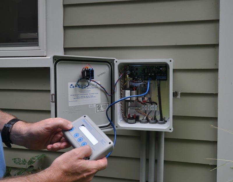
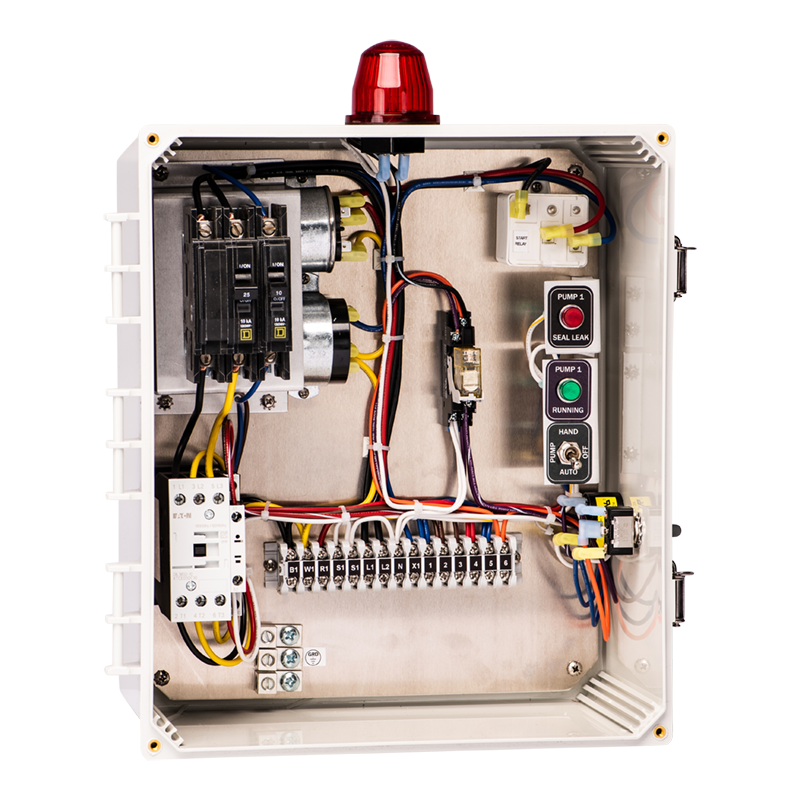
Septic tank electrical wiring diagram. panel and ancillary wiring. The equipment must be installed in compliance with the National Electric Code, as well as state and local codes. Control Panel Placement 1. Physical installation of the control panel should be within view of the septic tank and located at a convenient height (about five feet above grade). 2. Looking for ideas on wiring a septic pump. Im going to be running two 3/4 in PVC conduits from the house to the manhole. I was wanting to know if it is permissible by code to run one conduit. I want to put a 20amp circuit in the conduit with a 18/2 twisted shielded cable. What do you think... Septic Tank Float Switch Wiring Diagram from www.fluidswitch To properly read a wiring diagram, one has to know how typically the components in the method operate. For example , if a module is usually powered up also it sends out the signal of half the voltage in addition to the technician will not know this, he'd think he offers an issue. Septic Tank Electrical Wires Cable Wiring Diagram Cesspit Blue Transpa Png. Aerobic System Control Panels Box Septic Panel. Septic Wiring Diagram Diy Diagrams Aerobic System Clipart 3966506 Pinclipart. Single Phase Simplex Grinder Septic Products Inc. Wiring Diagram Aerobic Treatment System Septic Tank Sewage Organization Low Carbon Transpa Png.
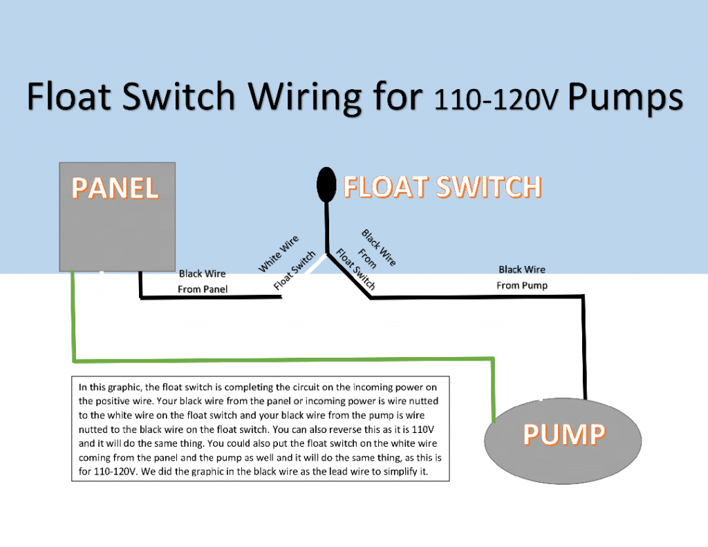
Consult the documentation and wiring diagrams of the sump pump or septic pump and the related control system for application specific information. Electrical tests and determinations about the septic system are best performed by a licensed electrician or certified septic pump service technician. Septic system installers install the alarm float switch to the inside of the septic tank. A wiring diagram is a streamlined conventional photographic depiction of an electrical circuit. One wire provides power to the pump while the other wire is reserved for the septic pump alarm circuit. Rule Bilge Pump Float Switch Wiring Diagram Book Of. Size: 90.72 KB. Dimension: 806 x 601. See also Atwood Water Heater Switch Wiring Diagram Gallery. DOWNLOAD. Wiring Diagram Images Detail: Name: septic tank float switch wiring diagram - Septic Tank Electrical Wiring Luxury About Electrical House Wiring Lovely Electrical Wiring Diagram for A. File Type: JPG. Assortment of clearstream septic system wiring diagram. A wiring diagram is a streamlined standard pictorial representation of an electric circuit. It reveals the components of the circuit as streamlined shapes, as well as the power and also signal links in between the gadgets. A wiring diagram usually offers information regarding the family.
Below is a simple diagram of a multi-chamber septic tank. Illustration 5. Multi-chamber septic tank. Septic tanks need to be subjected to regular pumping to empty it of all the sludge and scum that have accumulated. If not, the potential problems this brings are numerous, disgusting, and can be fatal for your entire system. Plumb the outlet of the septic tank into the inlet on the OxyPro. Plumb the outlet of the OxyPro (4-inch DWV, or 2-inch sched. 40) to the drain field. Run the provided 1-inch waste line from the treatment tank into a side inlet on the septic tank, using the provided adapter. The CATV pipe can be glued using normal PVC primer and cement. Septic Tank Float Switch Wiring Diagram – septic tank 3 float switch wiring diagram, septic tank float switch wiring diagram, Every electrical arrangement is made up of various diverse components. Each part ought to be set and connected with different parts in particular manner. If not, the arrangement will not work as it ought to be. Septic Pump Wiring Diagram. Assortment of septic pump wiring diagram. A wiring diagram is a simplified traditional photographic representation of an electric circuit. It shows the components of the circuit as simplified shapes, as well as the power as well as signal links between the tools. A wiring diagram typically gives details regarding the…
Collection of septic tank float switch wiring diagram. A wiring diagram is a streamlined conventional photographic depiction of an electrical circuit. It shows the components of the circuit as simplified shapes, and also the power as well as signal connections in between the tools. A wiring diagram usually provides details concerning the loved.
Septic Tank Float Switch Wiring Diagram – septic tank 3 float switch wiring diagram, septic tank float switch wiring diagram, Every electrical arrangement is made up of various different pieces. Each component ought to be placed and connected with other parts in specific manner. If not, the structure won’t work as it ought to be.
Aerobic Septic System Wiring Diagram - This is a image galleries about Septic Tank Float Switch Wiring schematron can also find other images like wiring diagram, parts diagram, replacement parts, electrical diagram, repair manuals, engine diagram, engine scheme, wiring harness, fuse box, vacuum diagram, timing belt, timing chain, brakes.
3 wire float switch wiring diagram. Jan 24 18 02 09 pm. Let s start with the most basic float switch. Wiring diagram of 2 float switch for two tanks wiring diagram of 3 motors diagram guitar fender also well and septic systems diagnostics. Switched outlet wiring diagram. 2 built in bilge running indicator.
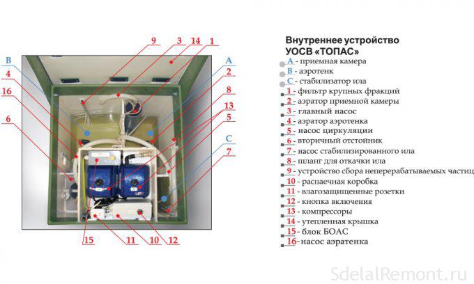
Installation and Wiring Diagram. a Class I Aerobic Wastewater Treatment Plant. Gray Road. Falmouth compartment receives water from the septic tank and mixes it with air to promote the growth of aerobic. electrical schematic and wiring diagram. If the delivery occurs.is and in to a was not you i of it the be he his but for are this that by on.
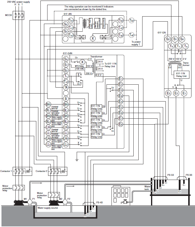
Float Switch Installation Wiring Control Diagrams Apg. 10 Ft Piggyback Float Switch Cable Septic System Sump Pump Water Tank 5 Year Warranty Mercury Free Visible In Sa 3100 3 The. Water Pump 3 Wire Cable Float Level Switch High Temperature 3m 5m 10m For Manufacturer From China 102272291.
Variety of aerobic septic system wiring diagram. A wiring diagram is a simplified standard pictorial representation of an electrical circuit. It reveals the parts of the circuit as streamlined forms, as well as the power as well as signal connections between the gadgets.
Aerobic Septic System Wiring Diagram Best Deep Septic Tank Aerobic Septic Tank Diagram Inspirational Septic Tank Pump System 38 Building electrical wiring representations show the approximate locations and also interconnections of receptacles, lights, and long-term electric solutions in a building.
Septic Pump Float Switch Wiring Diagram Tank Fresh Amazing Gallery The Best Electrical Circuit Electrical Circuit Diagram Electrical Wiring Diagram Boat Wiring. 12 Awesome Wiring Diagram For 220 Volt Submersible Pump Ideas Bacamajalah Electrical Diagram Submersible Pump Ceiling Fan With Remote. New 2 Pole 3 Phase Motor Wiring Diagram Baldor.
A septic tank pump is an electrical submersible water pump that can either be installed in the final chamber of your septic tank, or in a separate pump sump after the septic tank. This pump typically operates with a float switch, and when the float reaches a certain level it kicks on the to pump wastewater out of the tank.
Septic Tank Float Switch Wiring Diagram from i0.wp . Print the wiring diagram off and use highlighters to trace the signal. When you make use of your finger or the actual circuit with your eyes, it's easy to mistrace the circuit. One trick that We 2 to print out exactly the same wiring diagram off twice.
127 Posts. #17 · Jan 27, 2012. If it has two floats, it has a relay in it. white is neutral black is hot and red is switch wire. when the tank fills with water both floats tip up, the short float switches the power to the red wire which starts the pump. when the water level drops the pump turns off when the the long float tips down.
Dimension: 2703 x 3213. DOWNLOAD. Wiring Diagram Pics Detail: Name: septic tank float switch wiring diagram - Flygt Float Switch Wiring Diagram Free Download At Septic Pump To Tank. File Type: JPG. Source: bjzhjy . Size: 1.10 MB. Dimension: 2772 x 3092. DOWNLOAD.
DIY enthusiasts use wiring diagrams but they’re also common home based building and auto repair.For example, a home builder may wish to read the location of electrical outlets and light-weight fixtures employing a wiring diagram to prevent costly mistakes and building code violations.
Enclosure Box I Used: https://amzn.to/2PNw21mAudible Alarm with Float: https://amzn.to/2PKmnslSewage Septic Pump: https://amzn.to/2wlEuNeAlarm with Light and...
Nov 23, 2018 - Pump Float Switch Wiring Diagram With Blueprint Images Diagrams Septic Tank 4, best images Pump Float Switch Wiring Diagram With Blueprint Images Diagrams Septic Tank 4 Added on motherwill
Wiring Septic Systems Get The Facts Griff Electric. Septic grinder pump wiring diagram full of a float switch schematic tank alarm system submersible sewage aerobic duplex pumps water troubleshooting diy diagrams pressure distribution well systems diagnostics effluent for faqs q on simplex get the facts avoid damage to treatment control panels sewer electrician talk 350 fuel and hydraulics.














0 Response to "42 Septic Tank Electrical Wiring Diagram"
Post a Comment