42 Ct Cabinet Wiring Diagram
Overview. One of the most requested items of information that we receive is for wiring diagrams for the meters we sell. This page contains circuit type and wiring diagrams for all the form #'s of meters, sockets and pans; with and without CT's and PT's, for Wye, Delta, and Network circuits. ct cabinet wiring diagram schema wiring diagram. Architectural wiring diagrams produce a result the approximate locations and interconnections of receptacles, lighting, and unshakable electrical facilities in a building. Interconnecting wire routes may be shown approximately, where particular receptacles or fixtures must be upon a common circuit.
Can't seem to find my answer anywhere at the moment, but do I have to bond both service grounded conductors to ct cabinet. or will one suffice? Also, can I land GEC on seperate lug in ct, or do they have to tie together (I know the MBJ cannot be seperate, either wire, screw, buss, etc..)

Ct cabinet wiring diagram
current transformer wiring diagram & instructions note: we supply these meters on the assumption that they will be installed by a qualified electrician familiar with the installation of metering equipment ensure all current transformers are installed as per wiringdiagram (which can also be Get Ct Cabinet Wiring Diagram Images. Added 240/480v, 3 wire to wiring diagram prohibited condulets and junction boxes elevation is inspecting authority requirement, not fpl. Use the pcb placement guideline below to place pcbs in the correct slots. Ct Cabinet Wiring Diagram Free Download. Ct Cabinet Wiring Diagram. Ct Cabinet Wiring Diagram from 1.bp.blogspot Source: Ct Cabinet Wiring Diagram from
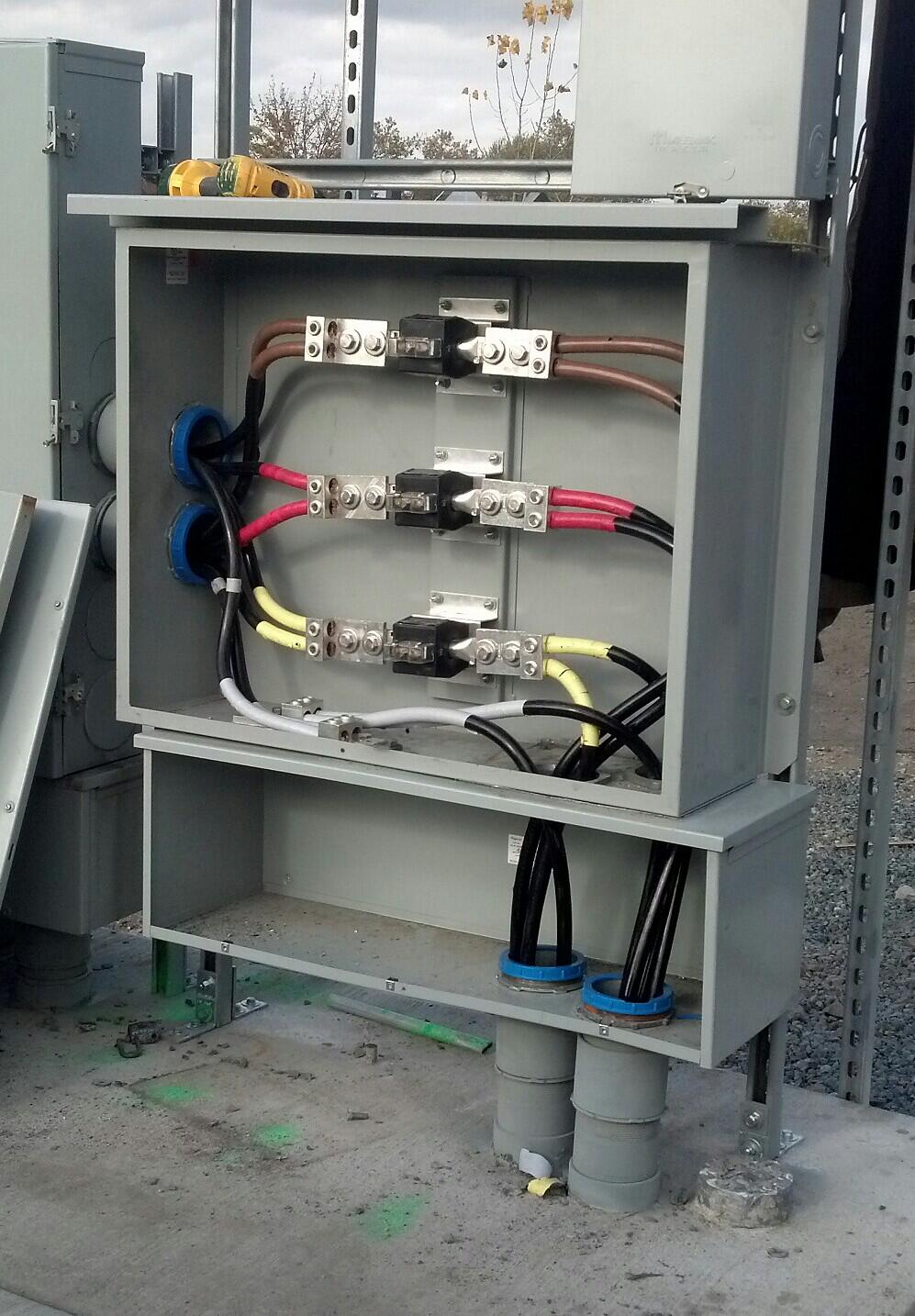
Ct cabinet wiring diagram. - pepco - single phase, 3 wire 120/240 volt meter wiring diagram 200amp oh service FIGURE 16 - PEPCO - SINGLE PHASE, 3 WIRE, 120/240 VOLT METER WIRING DIAGRAM 320 AMP vid jus shows the making up of a ct cabinet 3 phase. vid jus shows the making up of a ct cabinet 3 phase. Cur Transformer Physical Wiring Diagram Hqew Net. 47 ways to wire your power meter wrong negative kw readings electric tech amp connection roughrider cooperative inc lt ac three phase four panel how is the 11kv energy wiring cur transformer electricity 33kv bulk metering unit rockwill chint dtsu666 h with fusion solar app ct can and cabinet baldwin emc eme series faqs installation 3 via. Joined May 18, 2015. ·. 3 Posts. #5 · May 27, 2015. 120/208V 400 Amp 3 phase 4 wire coming in from street underground in Rigid steel conduit. Hits a 400amp non fused disconnect then the CT cabinet then the 400amp MCB Panel. No building steel (wood framed) with a 1 1/2" water service coming in near it - metal pipe.
Source: Ct Cabinet Wiring Diagram from www.ablegroup Source: Ct Cabinet Wiring Diagram from tse3.mm.bing Source: Ct Cabinet Wiring Diagram from www.hobut.co.uk Source: Ct Cabinet Wiring Diagram from umlusecasediagram.dominique-tiberi.fr Source: Ct Cabinet Wiring Diagram from i203.photobucket Source: Ct Cabinet Wiring Diagram CT/PT CABINET INSTALLATION FOR UNDERGROUND SERVICE DRAWING 11.8-4 August 2010 First Electric NOT TO SCALE Cooperative Corporation Main Disconnect: Readily accessible to Cooperative at all hours with no notice. 1. All material, except instrument transformers, meter, and meter socket, are to be furnished, installed, and maintained by the Member SERVICE EQUIPMENT 5-1-1 SEPT 2015 SIM-ESIG SIM-ESIG: 5-1 METER AND SERVICE EQUIPMENT 1. General Rules and Regulations. (a) To avoid unnecessary delay or expense, the customer or the customer's representative shall consult the appropriate DTE Electric Service Center before starting any wiring. (See pages 1-2-1 through 1-2-4 for Service Center locations.) 5.3 CURRENT TRANSFORMER METERS A current transformer meter mounting is to be installed for 4-wire loads for conductors sizes larger than the following: #3/0 AWG copper, Type RH; or # 4/0 AWG copper, Type R or T; or 250 Kcmil aluminum. The distance between a current transformer cabinet and the associated meter
120/240 volts, 3 wire single phase, 240 volts 3 phase 3 wire, 120/240 3 phase 4 wire, 120/208 3 phase 4 wire, 277/480 volts 3 phase 4 wire. Service voltages higher than 480 volts are available only by negotiation with the company. The size and type of the customer’s load must warrant such an installation. It is unusual for A. Single phase 2 wire 120 V B. Single phase 3 wire 120/240 V. NEC and the appropriate wiring diagram in the included in this drawings document. 5.4 CURRENT TRANSFORMER (CT)... 5.6 CT CABINETS CT cabinets will be furnished by HEC and will be padlocked and sealed by HEC. - pepco - single phase, 3 wire 120/240 volt meter wiring diagram 200amp oh service. figure 16 - pepco - single phase, 3 wire, 120/240 volt meter wiring diagram 320 amp oh & ug service. figure 17 - pepco - three phase, 4 wire, 120/208 volt meter wiring diagram 400 amp. figure 18 - pepco - three phase, 4 wire, 265/460 volt meter wiring diagram. Cabinets - CT Rated...70 - 71 CT Enclosures With Lift Off Covers... Wiring Diagrams .....62 - 64 Table of Contents B-Line series meter mounting equipment 1 Eaton. Eaton's B-Line Business 509 West Monroe Street Highland, Illinois 62249-0326 ...
Electric Service And Digital Meter Installation Requirements
CT (Current Transformer) Wiring connections for commercial Form 9S electric meter installation. Showing wiring from a current transformer in a cabinet to th...
Current Transformer Cabinet 400a 4000a Wall Mount On
In the above diagram i shown three ammeters current transformers, in the above CT wiring diagram i common a wire of all CT s, my means that i connect CT one connection with one another. I can also do it without connection with one anther but the main reason behind this is that in real life we do our wiring like above diagram in our main power.
Electric Service Installation Requirements Meter
Ct Cabinet Wiring Diagram Source: www.palmetto.coop Read cabling diagrams from negative to positive in addition to redraw the circuit being a straight collection. All circuits usually are the same : voltage, ground, single component, and changes.

Current Transformer Metering Ct Metering Overview B
fault current from the point of a ground fault on a wiring system to the electrical supply source. Figure 250-3 Author's Comment: In : Figure 250-3, EGC represents the equipment grounding conductor [259.118], MBJ rep-resents the main bonding jumper, SNC represents the

Lt Ac Three Phase Four Wire Panel Mounted Static Kwh Meter
Equipment Bond - supply side of Service and Main Bonding Jumper (CT Cabinets) Table 250.66. NEC 250.96, NEC 250.102 and NEC 250.142 . It is not necessary to run the bond from the CT cabinet back to the service disconnect if the CT cabinet is located on the supply side of the disconnect.
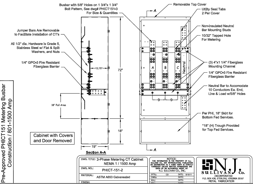
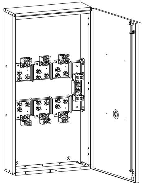
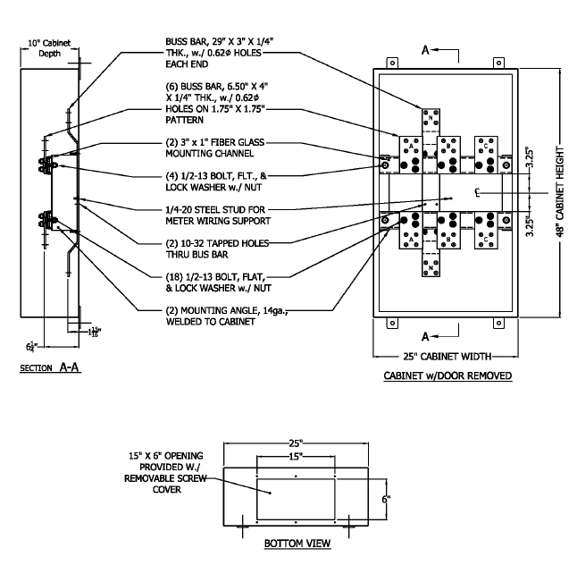
Ct Cabinet 3 Phase Metering Nema 1 N J Sullivan
Main service is comming into the ct cabinet in pvc, leaving the cabinet to a metal trough also pvc, out of the trough to the 800 amp main panel also pvc. I'll have to check on grounding the ct cabinet with the power company but I still need to ground the trough bonding will be done in main panel. Wire is 500 copper.

23 Circuit Amp Wiring Diagrams Ideas House Wiring Electrical
Ct Cabinet Wiring Diagram Free Download. Ct Cabinet Wiring Diagram. Ct Cabinet Wiring Diagram from 1.bp.blogspot Source: Ct Cabinet Wiring Diagram from
Service Amp Metering Requirements
CT rated meters are also typically demand meters as well. When CT's and PT's are used in a metering installation, the installation is known as being transformer-rated. Some people refer to the meters that use a CT PT combination or just CT's as a current transformer meter. Transformer-rated services run in parallel with the service.
Pin On Electrics Electronics
current transformer wiring diagram & instructions note: we supply these meters on the assumption that they will be installed by a qualified electrician familiar with the installation of metering equipment ensure all current transformers are installed as per wiringdiagram (which can also be
My Document
Current Transformer Types. There are four typical types of current transformers: window, bushing, bar, and wound.The primary winding can consist merely of the primary current conductor passing once through an aperture in the current transformer core (window- or bar-type), or it may consist of two or more turns wound on the core together with the secondary winding (wound type).
Pepco 400 To 800 Amp Nema 3r Ct Cabinet Phict83 N J Sullivan
Get Ct Cabinet Wiring Diagram Images. Added 240/480v, 3 wire to wiring diagram prohibited condulets and junction boxes elevation is inspecting authority requirement, not fpl. Use the pcb placement guideline below to place pcbs in the correct slots.
Lt Ac Three Phase Four Wire Panel Mounted Static Kwh Meter
The CT cabinet is on the supply side of the service and even though it is just a pass through CT (some are not) it is part of the service on the supply side and it, along with the service disconnect cabinet equals 2 enclosures.. With 500MCM wire, a minimum of a 1/0 must be used to bond the CT cabinet. Thank you Chris Kennedy. Till next time.....

Meter Sockets
DIY enthusiasts use electrical wiring diagrams however they are also common in home building plus auto repair. For example, a residence builder will would like to confirm typically the physical location of electrical outlets in addition to light fixtures utilizing a wiring diagram in order to avoid costly faults and building code violations.

How Do Ct Chambers Work Ct Chambers
Here we install the CT cabinet that Bob posted the photo of, unless we have a transformer mounted Ct's, in which we use a junction box, with lugs in it, but I have seen a few installs where both sets of 2/0 go up the riser pipe and the Ct's hang on the conductors at the weather head, with another 1" RMC stubbed up there with a weather head back.

Who Needs A Ct Chamber Ct Chambers
Ct Cabinet Wiring Diagram. Ct meter can and cabinet baldwin emc pt installation for underground service drawing 11 8 4 first electric cooperative corporation cur transformer metering n j sullivan parallel bonding electrician talk pepco 400 to 800 amp nema 1 phict81 ringless tranformer mmi electrical contractors resources electricians roughrider.
Comm 16
Ct Cabinet Wiring Diagram Source: www.palmetto.coop Read wiring diagrams from bad to positive in addition to redraw the routine like a straight range. All circuits are usually the same : voltage, ground, individual component, and switches.
Addc Guidelines For Energy Meter Installation
CT's Figure 11. Current Transformer Cabinets Overhead or Underground, Service Window Type CT's and PT's 277/480 Volt Figure 12. Current Transformer Cabinet Free Standing Overhead to Underground Service Figure 13. Pad-Mount Transformer Metering Installation Figure 14. Meter Installation from Pad-Mount Transformer using Bushing Type CT's
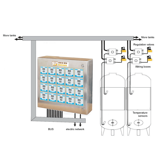
Cttcs A12s Fully Equipped Temperature Control System For 12 Pcs Of Cooling Zones With Central Controller Cabinet
CTSS - CT Cabinet and Switch are in separate enclosures which mount together (wired together in field by contractor). Can be configured for either underground or overhead service conductors; CABINETS MUST BE CONFIGURED TO SPECIFIC UTILITY METERING REQUIREMENTS (CONSULT FACTORY FOR SPECIFIC APPLICATIONS)
Ringless Metering Current Tranformer Metering
3 Hr 2 Min from Winged Horses. Jan 24, 2018. #2. The CT cabinet should be bonded to the service neutral/grounded conductors. Sometimes a jumper is used if the neutral bus is isolated from the cabinet. You could have the GEC to the ground ring connected there also if you desired. Here is a set up like that: S.
Current Transformer Cabinet 400a 4000a Wall Mount On

Karins Notes Electrical Are 5 0 Community
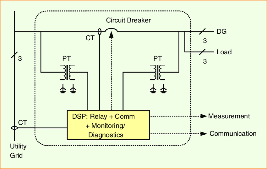
Schematic Diagram Of Circuit Breaker Opening And Closing

Safely Isolating A Single Phase On A Ritherdon Ct Chamber
Electric Service Equipment

System Wiring Diagram Smartlogger2000 User Manual Huawei

Cttcs A25s Cabinet Tank Temperature Control System For 25 Cooling Zones
Instrument Rated
Oliveri Electric On Twitter 400 Amp Ct Cabinet Http T
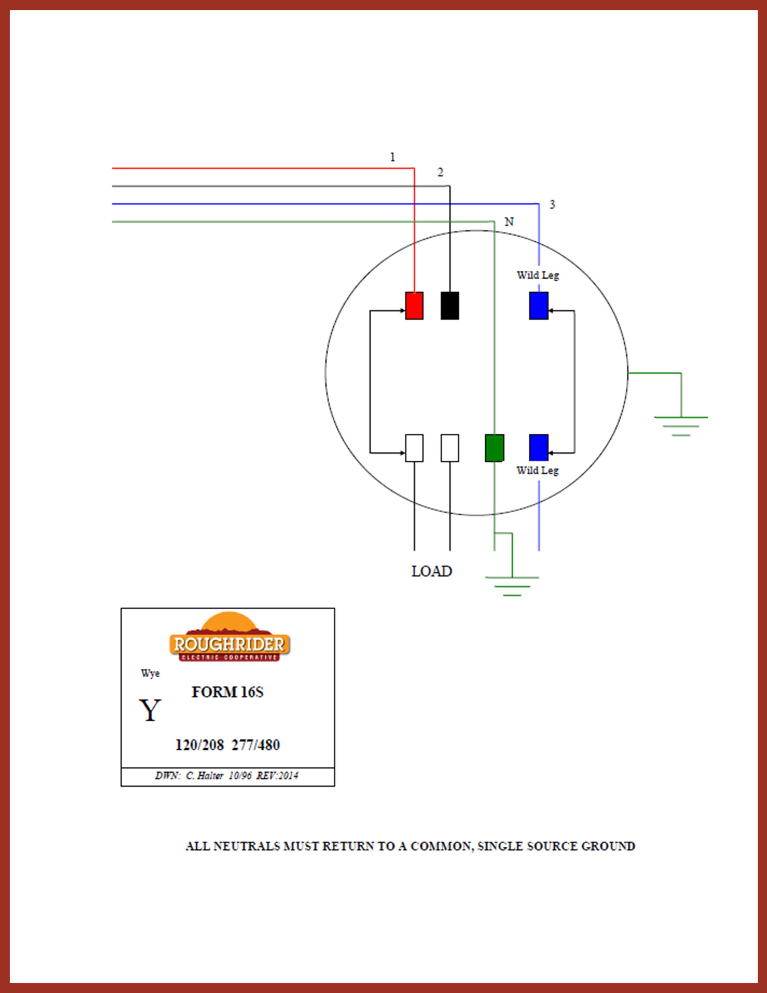
Resources For Electricians Roughrider Electric Cooperative Inc

Service Amp Main Bonding Jumpers
Comm 16
Butler County Rural Electric Cooperative
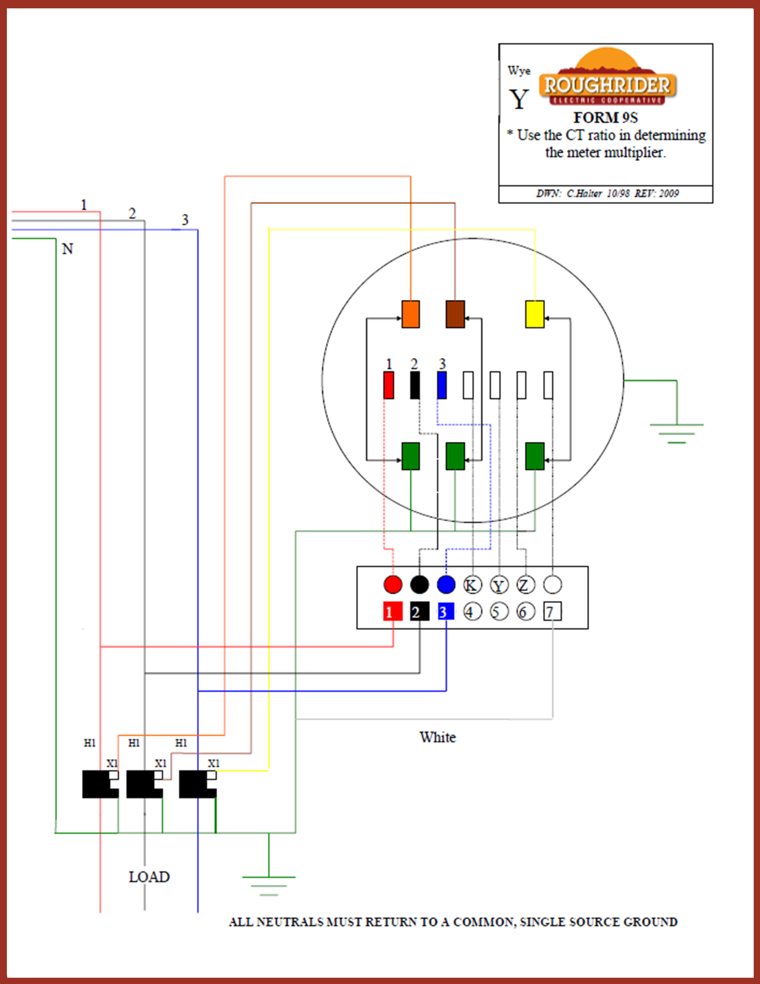
Resources For Electricians Roughrider Electric Cooperative Inc

Ct Cabinet With Only 2 Ct S In It Ecn Electrical Forums

Drilling Rigs Power Supply Methods To Enhance The
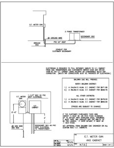
Ct Meter Can And Cabinet Baldwin Emc

Inspirational Ge Motor Starter Wiring Diagram Washing
My Document
Con Edison Equipment Con Edison Approved Meter Sockets

Complications In Disaggregation Of Electrical Feeds
2020 Guide To Metering
F Mep Amp Procedures Mes 298 1 Bus And Cabinet Details For
0 Response to "42 Ct Cabinet Wiring Diagram"
Post a Comment