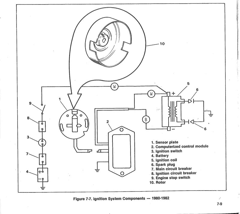
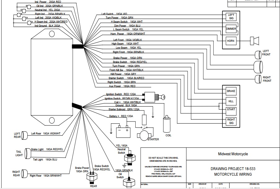
40 Harley Ignition Module Wiring Diagram
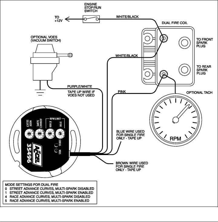
3. Coil connection. Typically, there is a white wire from the Run/Stop switch on one of the coil primary terminals. On the same terminal, there Is a second white wire going to the stock ignition module. These wires are the +12V supply to the coil and the +12V supply wire to the stock ignition module. The S&S Ignition Installation Kit for 1999-2003 Harley-Davidson® Twin Cam 88® (S&S #55-1012 See Picture 1) is intended only for installation of S&S Intelligent Spark Technology (IST) Ignition Module. See Picture 2. S&S Ignition System Installation Kit #55-1012 contains the following items (See Picture 1): CAUTION
wiring diagram: fxs shovel kick/electric, no turn signals ignition switch hi-lo horn horn switch tach speed hi beam oil light neutral light oil switch neutral switch electronic distributor alternator headlight run switch starter switch voltage regulator starter motor starter solenoid 30 a breaker battery bus starter relay taillight 30 long.

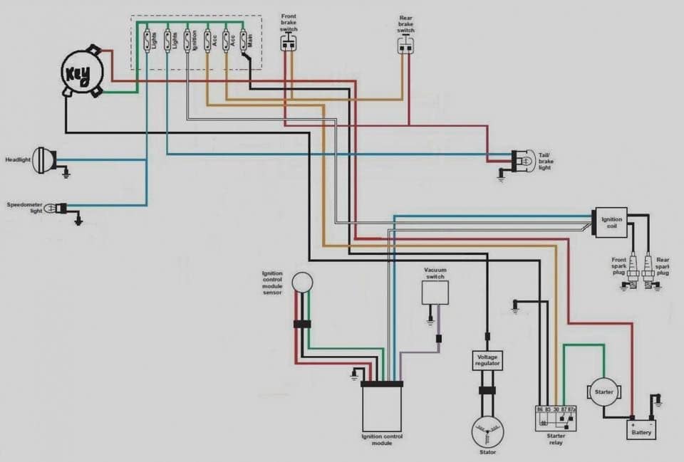
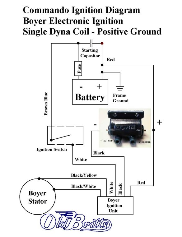
Harley ignition module wiring diagram
Fuse/Relay LocationFuse Amp RatingPassenger Compartment Fuse Panel Description115AAdjustable Pedals2-Not Used3-Not Used420APower Point Instrument Panel5-Not Used620ATrailer Tow Turn/Stop Relay730AHigh Beam Headlamps/Flash to Pass815ABackup Lamps (Diesel Engine Only)920AHeated Mirrors1010AA/C Clutch1120ARadio (MAin)1220ACigar Lighter / OBD II135APower. Sep 10, 2009 · Bypassing Ignition Switch on 1979 Dodge Ramncharger I want to bypass the current ignition switch and be able to use toggle switches to control ignition, assecories, etc. 110 Quad Wiring Diagram For Ignition Switch 110cc pocket bike wiring diagram pinterest, motorcycle diagrams page 38 circuit wiring diagrams, how to bypass an. S&s Ignition Wiring Diagram. Consult an appropriate service manual for your motorcycle for correct The HI- 4N ignition system is intended for use on Harley-Davidson®. Read online or download PDF • Page 8 / 14 • S&S Cycle IST Ignition System for S&S V-Series Engines with Flywheel Machined for Crank Trigger User Manual. Installation.
Harley ignition module wiring diagram. The Twin Tec TC88 ignition replaces the original equipment (OE) ignition module on 1999-2003 Harley-Davidson( motorcycles with carbureted Twin Cam 88( engines.. If you are making your own wire harness, please note that H-D® wiring diagrams show an incorrect view of the MAP sensor and mating connector. Please refer to the TC88 Tech FAQ on... I need to replace my ignition module and the original part is not made any more. It was 32414-84a. The newer part has a plug on it that doesn't match the current connections on the bike so I am trying to track down a good wiring diagram for the ignition module. Any advice is appreciated. This Screamin' Eagle ignition module is intended for A Service Manual for your motorcycle is available from your. Harley-Davidson. My ICM (screaming eagle) has 7 wires. If the ignition coil has two terminals, it's a dual fire coil meaning both cylinders fire together every Do you have a factory service manual with wiring diagram for either an. How to Wire A Coil On A Harley. - Encouraged to help my weblog, in this occasion I am going to show you about how to wire a coil on a harley.. And now, this is the first photograph: Electrical Wiring Diagram Motorcycle With images from how to wire a coil on a harley , source:pinterest . XX 7178] Ignition Coil Wiring Diagram Harley.
Nov 24, 2019 · Dyna s ignition wiring diagram harley. 5%. You’ve already determined ground and tail wire colors in your 3-wire brake/tail light. Use as reference only. e. #5 · Mar 13, 2017. This tail lamp fits numerous models and platforms from 1999 up to the current year.. but I can almost bet it is the module. All of the Harley... I would like a 2002 Harley Davidson wiring diagram of an electronic igintion, ie., how to install/I am changing points to an electronic ignition. I have one that has 2 wires coming from it and another with 3 wires. 99949-01_en - 2001 Wiring Diagrams. Specification. 2001 ALL XL 1200S DOMESTIC and INTERNATIONAL MODELS, MAIN HARNESS, SHEET 1 OF 5. 2001 ALL SPORTSTER DOMESTIC and INTERNATIONAL MODELS, STARTING & CHARGING, SHEET 2 OF 5. 2001 ALL XL 1200S DOMESTIC and INTERNATIONAL MODELS, IGNITION CIRCUIT, SHEET 3 OF 5. S&s Ignition Wiring Diagram. Consult an appropriate service manual for your motorcycle for correct The HI- 4N ignition system is intended for use on Harley-Davidson®. Read online or download PDF • Page 8 / 14 • S&S Cycle IST Ignition System for S&S V-Series Engines with Flywheel Machined for Crank Trigger User Manual. Installation.
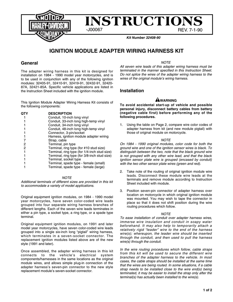
Calterm Illuminated 12-Volt DC/20 Amp Rocker Switch, Red (18) Model# 40310. Building Electric Trim Tabs Since Switch wiring kit with Deutsch Remove Bennett actuators, and install Lenco Wiring diagram and installation. [email protected] [email protected] Brand new 40 ton Manitex 124' boom truck crane on PEterbilt 567 Tri-drive truck for sale. before installing the new ignition module. When replacing the early style ignition module on 1984 - 1990 model year vehicles, however, a new adapter wiring harness must also be installed to allow plug-in connection with the new ignition module. See your Harley-Davidson dealer regarding availability of Ignition Module Adapter Wiring Harness Kit. Feb 19, 2016 · The voltages used on these circuits are very small and hard to test. The easiest way to test a computer module is by verifying its power and ground connections are correct. To test your module's power and grounds: Find the wiring diagram for your year's Sportster in a service manual, or from your local Harley dealership. Refer to Figure 3. Remove OE ignition module and wire harness (items 1-4). You will disconnect two wires at the coil, a wire going to the VOES (Vacuum Operated Electrical Switch), ans a ground wire at the module, and the 3 pin plug (20) that connects to the sensor plate. Refer to shop manual for locations. 3. Remove ignition cover plates and.
Harley Ignition Module Wiring Diagram. Effectively read a electrical wiring diagram, one offers to know how typically the components within the system operate. For example , if a module is powered up also it sends out a signal of fifty percent the voltage plus the technician would not know this, he'd think he provides an issue, as this.
Wiring diagram of ignition module plug and witch wires should power up with the key on Read full answer Be the first to answer Apr 13, 2011 • 2000 Harley Davidson FLHTCUI Electra Glide...
FXR Wiring, Charging, & Ignition Systems — FXR Division. FXR Division Stainless Steel FXR Side Panels w/ Well Nut Kit. 179.99. MotoGadget M.Unit- Basic.
Harley 32449-95a Color Code Wiring Diagram. When this window passes the Hall Effect sensor an electrical pulse is. the ignition module from the stock HD# A to a FXRP IGNITION MODUEL Harley's position on this is pretty clear from this statement, dated Color Code. .
Oct 19, 2021 · Touring Models - 2015 Electra glide FLHTP WIRING ignition and brake accessory - Hello! I am the owner of a new to me 2015 Electra Glide FLHTP. I am trying to wire accessories into the ignition wire and have no clues what color wire I need to splice into. I am trying to install dash cams and am at a loss. Where can I...
The Wolf came up with this basic wiring diagram as he was putting this bike together from the frame up. I thought it was the coolest thing I had ever seen s...
Wiring Power To New Dyna 2000i Ing Module Harley Davidson Forums 2006 all dyna dom. Sportster dyna 2000 ignition wiring diagram. Models lighting circuit sheet 6 of 12.. Harley Dyna Ignition Switch Wiring Diagram Wiring Diagram Online Amazon Com Dynatek 2000 Hde Programmable Digital Ignition System
1995 Harley davidson dyna service manual free download 1996 harley dyna 1997 service manual download 1998 harley dyna had oil on spark plug what is cause 1999 harley dyna super electrical troubleshooting how to fix cylinder knock 2000 harley dyna fxdf how to rebuild a 2001 harley dyna carburetor ignition module sensor wiring diagram for 2002 harley dyna pdf dyna fxd 2003 repair manual dyna.
Sep 10, 2009 · Bypassing Ignition Switch on 1979 Dodge Ramncharger I want to bypass the current ignition switch and be able to use toggle switches to control ignition, assecories, etc. 110 Quad Wiring Diagram For Ignition Switch 110cc pocket bike wiring diagram pinterest, motorcycle diagrams page 38 circuit wiring diagrams, how to bypass an.
Turn off the ignition to exit the module selection menu.. If neither side displays 12 volts, there is a problem with the ignition switch or the wiring between the fuse and ignition switch. Figure 2. The fuse box diagram. Figure 3. The fuse box is near the battery.... A wiring diagram of the stator and voltage regulator.
Understanding The Ignition System Electronic Ignition Module Kit K2543 Electronic Ignition Overview Electronic Ignition For Old Cars Electrical Diagram Circuit. 1d809 Harley Single Fire Ignition Wiring Diagram Digital Resources Ford Electronic Ignition Wiring Diagram 1983 Automotive Wiring
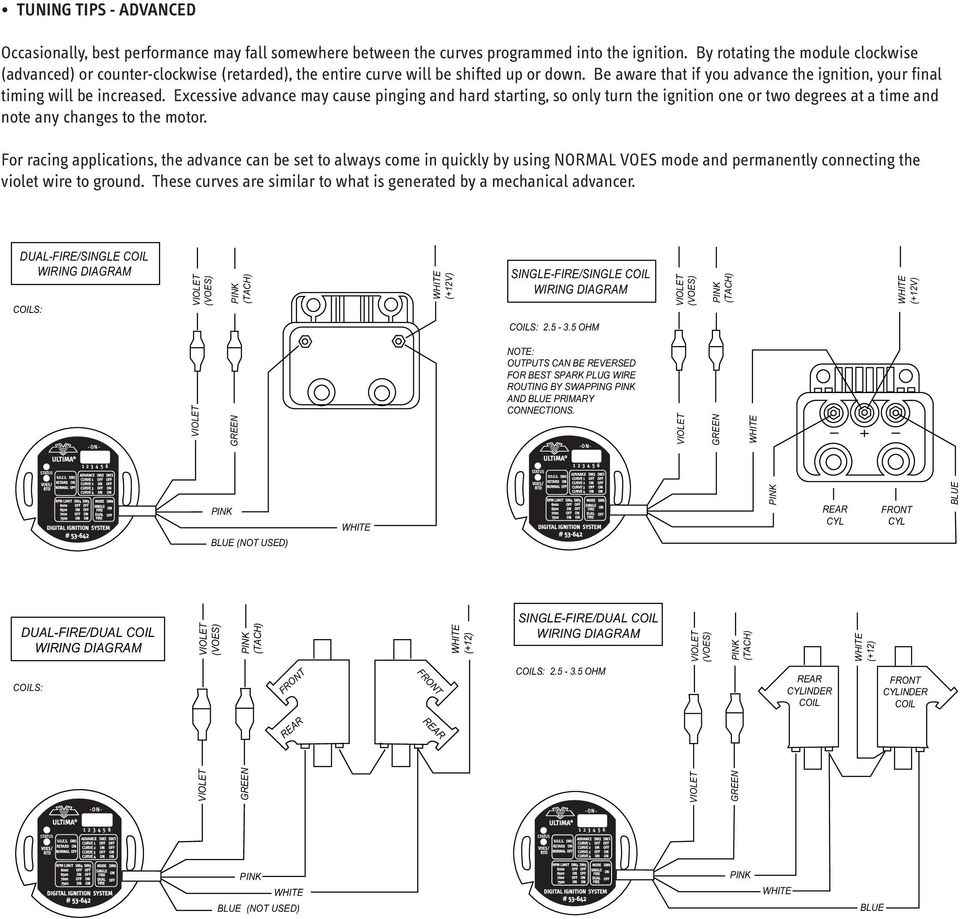
ULTIMA® #53-644 Programmable Digital Ignition System • DESCRIPTION The Ultima® Digital Ignition is designed to provide the correct curves and total timing for Ultima enginesand other larger cubic inch or high performance engines. These units will also replace the OEM HD® factory ignition module and sensor used on 1983 and later Harley-Davidson EVO motors.
Harley Ignition Switch Wiring Diagram Download. harley ignition switch wiring diagram - Exactly What's Wiring Diagram? A wiring diagram is a kind of schematic which utilizes abstract photographic symbols to show all the interconnections of parts in a system. Circuitry diagrams are made up of two points: signs that represent the elements in the circuit, and…
The 12 volt wire from the ignition switch is also connected to that end of one of the coils. Connect the red wires from the DYNA S to that same end of one of the coils. 12: Connect the black wire to the other end of the coil for the front cylinder. 13. Connect the white wire to the other end of the coil for the rear cylinder. 14.
Fuse/Relay LocationFuse Amp RatingPassenger Compartment Fuse Panel Description115AAdjustable Pedals2-Not Used3-Not Used420APower Point Instrument Panel5-Not Used620ATrailer Tow Turn/Stop Relay730AHigh Beam Headlamps/Flash to Pass815ABackup Lamps (Diesel Engine Only)920AHeated Mirrors1010AA/C Clutch1120ARadio (MAin)1220ACigar Lighter / OBD II135APower.
Peterbilt 579 (Stock #2684) Cab & Cab Parts / Interior Misc Parts. 0 By John Lee (HELLBOYs) https://www. 5kb: Download: Peterbilt 348 Schematics wiring diagram. pmd 10 5/27/2004, 7:59 pm We have a 2009 Peterbilt model 386 and need a wiring diagram so we can figure out the headlights. He is not perfect but the log is error-free.
Stock 97 Evo motor has 3 wire (red,green, black) with triangle plug coming from cam plate ignition. How do I run these to a coil? Does it require a separate electronic module? I have not even begun any wiring nor have I acquired any components other than the plug in rectifier/regulator. I need a simple diagram and some instruction.
The wire from the ignition switch to the ignition coil primary terminal plastic grommet (10) over the black and red wires from the ignition module and push it into. Evo Classic Models - Wiring Diagram for Compu-fire HD-2 Coil - I'm trying to install a Compu-fire HD-2 single fire coil on my '95 evo.
Harley Davidson Softail Ignition Switch Wiring Diagram Source: wiringall . Read electrical wiring diagrams from unfavorable to positive and redraw the circuit like a straight range. All circuits are the same ~ voltage, ground, individual component, and buttons. Harley Davidson Softail Ignition Switch Wiring Diagram Source: w7.pngwing .
Screaming Eagle Ignition Module Instructions The SE ignition module was rebuild a harley dyna carburetor ignition module sensor wiring diagram Screamin' Eagle ignition module for 86 to 93 Sportster XL/ Pro - Series Ignition instructions: SE module part # is and SE module part # is and for the rpm limit modules.
Nov 05, 2021 · Hi, does anyone have a wiring diagram for lexmoto assault efi 2019, the ignition switch they sell on cmpo doesn't fit to wiring loom on bike:))). They is a 6 pin plug with red, black and brown on bike and an 6 pin plug with red, black, green, black/white on ignition switch all of them in completely different positions.
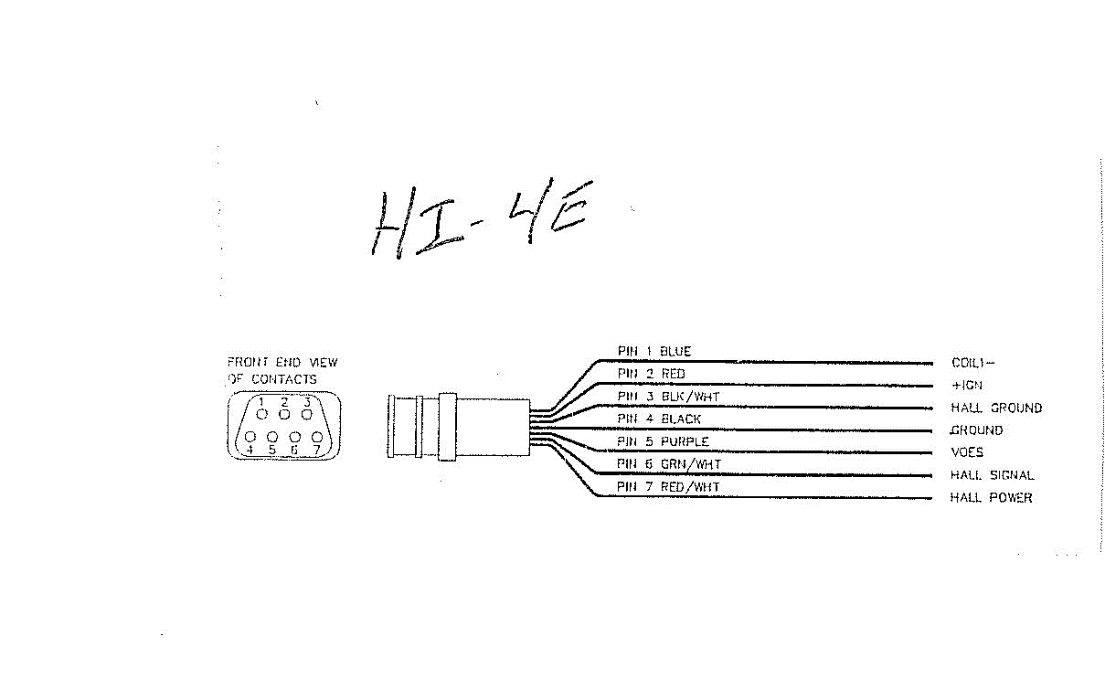
Harley-Davidson® motorcycles. The HI-4 replaces the original equipment (OE) electronic ignition system on 1978 and later models as well as the points and mechan-ical advance on early models. HI-4 Single Fire Race Ignitions (P/N 8-2100 ignition module only and P/N 8-4100 ignition kit) are true single fire, even at cranking speed.
The DYNA 2000i Digital Ignition is designed to replace the factory ignition module and sensor used on 1983 and later Harley-Davidson EVO motors. It is also an ideal upgrade for early electronic and breaker-point systems that require a mechanical advancer. The entire ignition fits inside the engine in place of the cam sensor or point plate
Harley Ignition Module Wiring Diagram from www.shaunmayfield Effectively read a cabling diagram, one provides to know how typically the components inside the program operate. For example , in case a module is powered up and it also sends out a signal of 50 percent the voltage and the technician does not know this, he would think he provides.
Nov 02, 2021 · When and How to Use a Wiring Diagram Feb 06, 2019 · Harley ignition switch wiring diagram collection harley davidson ignition switch wiring diagram lovely unique. Free Johnson Outboard Wiring Diagram Pdf. com Force Wiring Diagram 2 from ignition switch wiring diagram on a 60 hp mercury outboard , source:obd2. Super high amount of views.
SOURCE: wiring diagrams for a ignition module on a yamaha. Hi and welcome to FixYa, The post is under an 81 Yamaha XJ650 and the need is for the wiring diagram (of the ignition module). Should you be interested, here is the wiring diagram of the entire bike. Good luck and thank you for asking FixYa. Posted on Dec 07, 2009
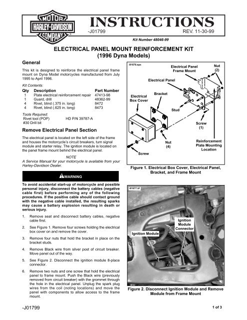
Faulty ignition module operation may result from wiring harness problems. If this Screamin' Eagle ignition system malfunction exists, inspect the motorcycle's wiring harness to determine if it is faulty. If the existing wiring harness is faulty, repair or replace it before installing the new ignition module. NOTE
Jan 01, 2014 · It only takes a short period of time to burn up the module using a coil with the wrong resistance. When you select a coil for any High power CD ignition box like the Mallory Hyfire CD boxes, the Mallory Hyfire CD boxes MUST always use a coil with LESS than 1 Ohm of primary resistance.











0 Response to "40 Harley Ignition Module Wiring Diagram"
Post a Comment