39 Jockey Pump Piping Diagram
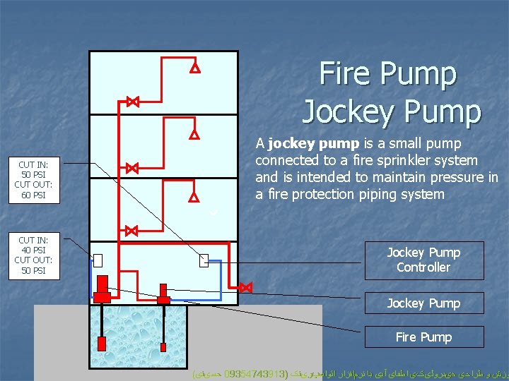
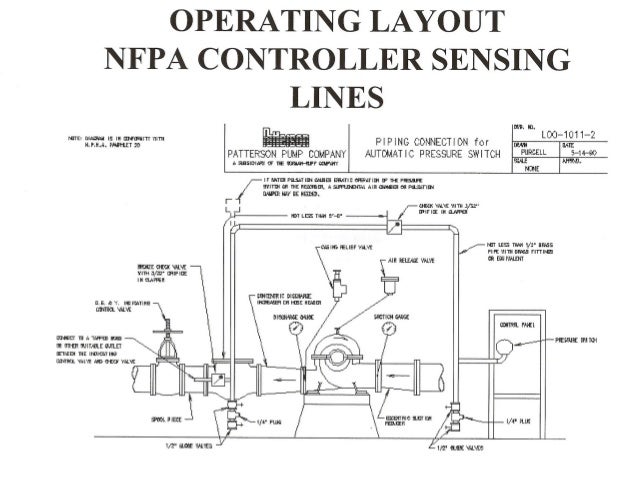
Jockey Pump Piping Diagram. A jockey pump is a small pump connected to a fire sprinkler system and is intended to maintain pressure in a fire protection piping. Questions about the orifice checks in the SENSING LINES has come up quiet often. The above capture is an age-old drawing covering sensing lines for a jockey pump and fire pump controller. Directions for Installing Sensing Lines in Jockey and Fire Pump Systems. March 12th, 2019. Both fire pump system and jockey pump control panels get their run signal the exact same way through a half inch non-ferrous pipe commonly referred to as a sensing line.. Sensing lines should be piped the exact same way on both the fire and jockey pumps.
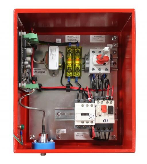
STANDARD JOCKEY PUMP CONTROLLER NEMA TYPE 3R ENCLOSURE A TYPICAL STANDARD JOCKEY PUMP CONTROLLER ELECTRICAL SCHEMATIC PS1 L2A/N 0.33 - 2 240/1/60 (1) #14 AWG (1) [2 MM SQ.] HAND OF F AUT O Patterson Jockey Pump Control Panel Model No. Voltage H.P. Rating Serial No. Encl. Type FLA. A SUBSIDIARY OF THE GORMANN-RUPP COMPANY MADE in U.S.A. 12.01
Jockey pump piping diagram
facilitate isolation of the jockey pump controller (and sensing line) for maintenance without having to drain the entire system. [See Figures A-7-5.2.1 (a) and (b).] A-7.5.2.1(e) The pressure recorder should be able to record a pressure at least 150 percent of the pump discharge pressure under no-flow conditions. The Jockey Pump, an Important Part of a Fire Pump System. August 1, 2009 Rev. No. 2 A Jockey Pump is an important component of a fire pump system. The Jockey. Choosing a PMP for an interior piping system, supplied by a fire pump system taking suction directly from a water supply without any underground, is a very A jockey pump is a small pump connected to a fire sprinkler system to maintain pressure in the sprinkler pipes. This is to ensure that if a fire-sprinkler is activated, there will be a pressure drop, which will be sensed by the fire pumps automatic controller, which will cause the fire pump to start.
Jockey pump piping diagram. A jockey pump is a small pump connected to a fire sprinkler system to maintain pressure in the sprinkler pipes. This is to ensure that if a fire-sprinkler is activated, there will be a pressure drop, which will be sensed by the fire pumps automatic controller, which will cause the fire pump to start. JPx Series - Jockey Pump Controllers. Designed to control jockey pumps which maintain water pressure in fire pump serviced systems. Prevents unnecessary starting of the fire pump due to small leaks in the sprinkler system piping. HP rated fuse-less thru-the-door main disconnect switch. A jockey pump, also know as a pressure maintenance pump, maintains the pressure in the fire sprinkler system to avoid non-emergency starting of the main fire pump. This keeps the main fire pump from short cycling, which shortens its life span. The jockey pump is designed to start before Name: fire pump controller wiring diagram - Fire Pump Piping Diagram Inspirational Jockey Pump Piping Diagram; File Type: JPG; Source: kmestc ; Size: 105.58 KB; Dimension: 800 x 541; Essential Tips for Safe Electrical Repairs. Repairing electrical wiring, over another household project is all about safety. Install an outlet properly and it.
Master Model JPCE, Jockey Pump Controllers, are used in installations designed to NFPA-20, Standard for the Installation of Stationary Fire Pumps for Fire Protection. They are designed to maintain the system pressure so the fire pump does not start due to small leaks in the system. Figure A-10-5.2.1(a) Piping connection for each automatic pressure switch (for fire pump and jockey pumps). If water is clean, ground-face unions with non-corrosive diaphragms drilled for 3/32-in. orifices can be used in iretrol jockey pump controller ockey pump brass sensing line ire pump brass sensing line 'retrol fire pump controller w.- supply rundfos cri-12 60 hrtz 3550 jockey pump supply with o.s.& jockey pump discharge with atterson mma fire pump ratel 6" discharge 20 rl-l transfer switch 3 phase jockey pump eck valve and o.s.& y. ) for 1000 gpm @ 125 psi any mechanical difficulties with the pump or motor. The 384 pump was properly aligned, if supplied with a motor, at the factory. However, since the pump base is flexible, it may spring and twist during shipment. Do not pipe the pump until it is realigned. Realign the base after piping is completed and after the pump is grouted in and bolted down.
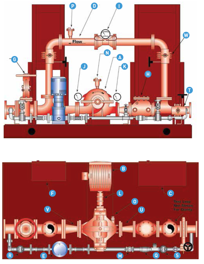
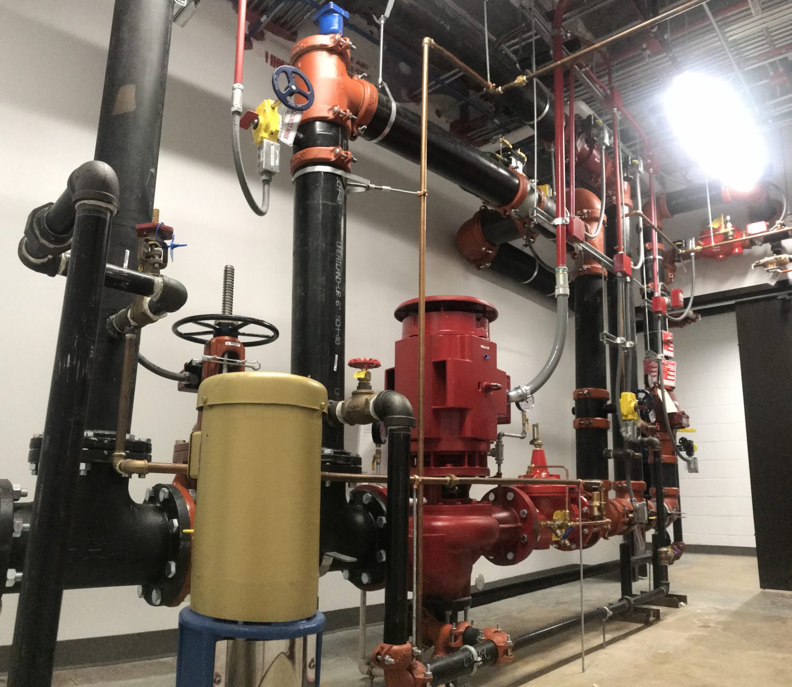
Jockey pumps are an optional addition. NFPA20. ULR. Fully NFPA 20 & NFPA 13R compliant. Flow rates range from 50 to 1500 GPM with pressures up to 160 PSI. System options include test headers, flow loops, city bypass loops, jockey pumps, and an array of controllers to choose from. This photograph fire and jockey pump controller sensing lines mike trumbature with regard to fire pump wiring diagram. Obviously power to fire pump motor must be supplied by a reliable single source or by reliable multiple sources. D = Jockey Pump Controller C D A B January 2009 From Supply To System F E FIRE PUMPS ΠSENSING LINES Most commonly the pump controller is connected to the fire protection system by means of piping know as a sensing or pilot line. Each pump, including the jockey pump, shall have its own individual A jockey pump, also known as a pressure-maintenance pump, is a small apparatus that works together with a fire pump as part of a fire-protection sprinkler system. It is designed to keep the pressure in the system elevated to a specific level when the system is not in use, so that the fire pump doesn't have to run all the time and the system.
Design Of A Building Fire Pump System With Integrated Parallel
Jockey pumps mitigate false alarms by compensating for small pressure fluctuations in system piping and return the system to its normal static pressure range under non-fire conditions. As with a fire pump, the jockey pump installation will include a controller with a pressure switch.

Fire Water Pump Station Design Piping Instrumentation
ZJBetter Jockey pump installation instructions. Pump should be installed in well-ventilated anti-freezing. pump and motor away from the obstacles of at least 150mm. to ensure the smooth motor cooling. Minimize the extent to import pipe friction losses, water piping should be as short as possible, and a larger size pump caliber.

Fire Water Pump Station Design Piping Instrumentation
The Jockey Pump, an Important Part of a Fire Pump System. August 1, 2009 Rev. No. 2 A Jockey Pump is an important component of a fire pump system. The Jockey. Choosing a PMP for an interior piping system, supplied by a fire pump system taking suction directly from a water supply without any underground, is a very
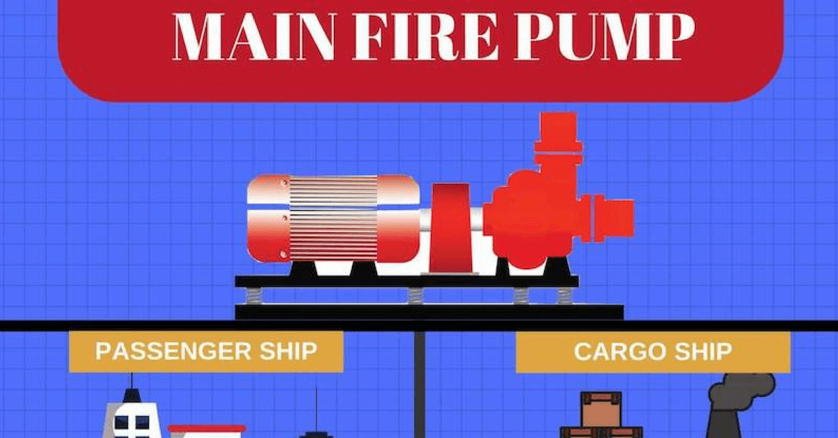
A Guide To Fire Pumps On Ship
facilitate isolation of the jockey pump controller (and sensing line) for maintenance without having to drain the entire system. [See Figures A-7-5.2.1 (a) and (b).] A-7.5.2.1(e) The pressure recorder should be able to record a pressure at least 150 percent of the pump discharge pressure under no-flow conditions.
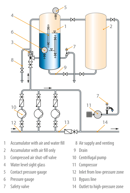
Accumulator Ksb
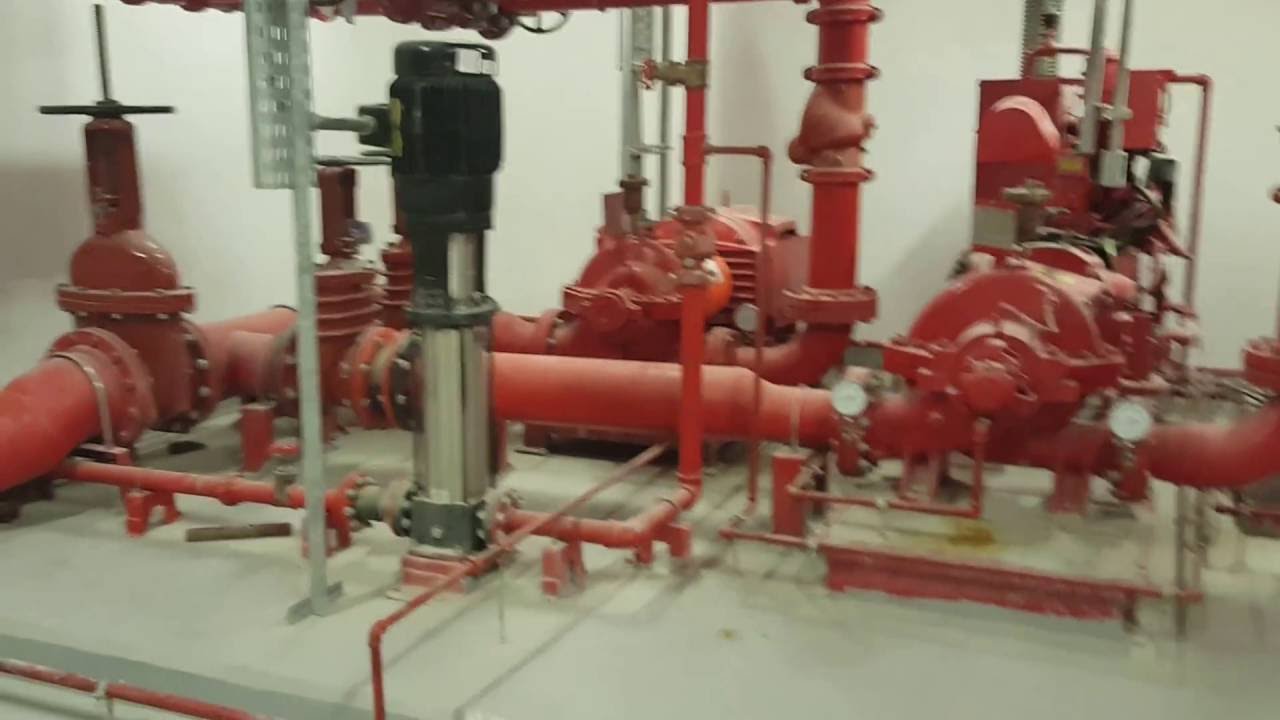
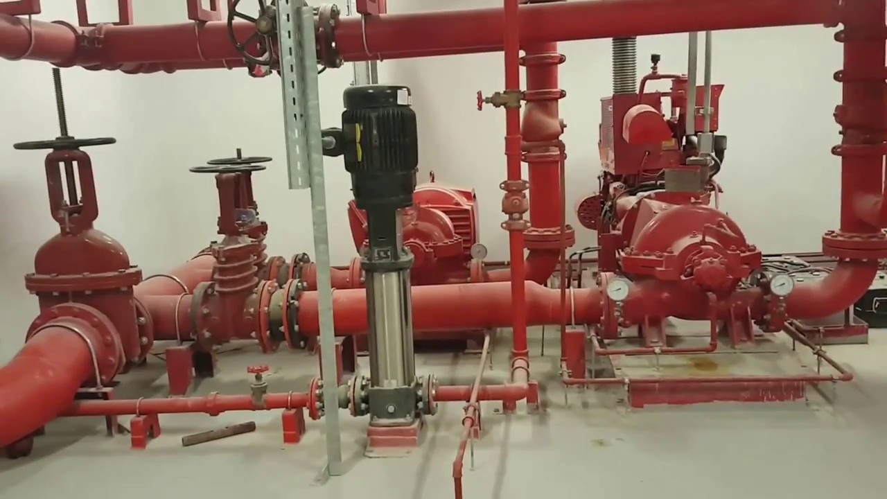
Hence the name "jockey pump." The purpose of a jockey pump is to maintain pressure in a fire protection piping system so the larger fire pump does not need to run. A jockey pump package consists of a pump, motor and controller. Two Types of Pumps. There are two types of pumps available for jockey pump applications.

69275070 Nfpa20 Presentation Fire Pumps Pdf Document
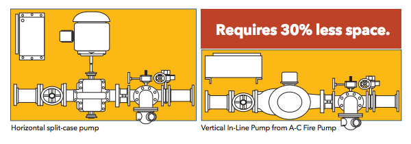
These pumps require significantly more space, and present special layout considerations. The pump suction line for side suction pumps shall have a minimum straight run of three pipe diameters (for non-API pumps) or five pipe diameters (for API pumps) between the suction flange and the first elbow, tee, valve, reducer and permanent strainer.
Fire Pump System
Pumps should never support the suction or discharge piping. Any stress on the pump casing by the piping system greatly reduces pump life and performance. Keep in mind that increasing the performance of the pump will help to make up for piping mistakes made on the discharge side of a pump.
National Fire Protection Agency Nfpa N N A
1- For situations where the jockey pump serves only above ground piping for fire sprinkler and standpipe systems: The jockey pump should be sized to provide a flow less than a single fire sprinkler. The main fire pump should start and run (providing a pump running signal) for any water flow situation where a sprinkler has opened, which will not.
Fw Pump Basis Nfpa
2.4.3 Refer to fire pump panel and jockey pump panel wiring diagrams for additional switch/alarm connections. 2.5 MISCELLANEOUS CONNECTIONS 2.5.1 Certain items are shipped loose and are intended to be field installed. Items that may be shipped loose are: hose header and valves, muffler, 10ft fuel tank vent pipe, ball drip valve. If applicable
.jpg)
Yuta News Amp Events The Importance Of Pressure Reducing
Main fire pump and Jockey pump sensing lines totally independent of each other and connected to their respective controllers in accordance with NFPA 20 9-5.2.1. & (a), Figures A-7-5.2.1 (a) & (b). 2.
304 2437 Brandschutz En Rz Layout 1
JPCV and PMCVE Drawings. Dimensionals. 10605 - JPCV: NEMA 2, Variable Speed Jockey Pump Controller. 24180 - PMCVE: NEMA 2,12 Variable Speed Pressure Mainenance Controller. External Wiring. 10604 - JPCV: Three Phase Variable Speed Jockey Pump Controller.

Piston Typ Druckminderer Und I Formige Wasserschlagdampfer
Diagrams --Typical Pump Installations. The information provided here is for educational purposes only. Technically qualified personnel should install pumps and motors. We recommend that a licensed contractor install all new systems and replace existing pumps and motors. Failure to install in compliance with local and national codes and.
التخفيف كربون إيقاف Nfpa Fire Pump Installation Diagram
Piping 5 Setting the Pressure Switch 6. The controller is intended to be mounted to a wall or a welded structure that is part of the pump package. Refer to the Outline Diagram for mounting hole sizes and locations. If the controller is... The jockey pump controller has a Hand-Off-Auto selector switch on the right hand side of the

Fire Pumps Sensing Line Fire Protection Specialists
Layout arrangement for Centrifugal Pump Piping 1. GENERAL. The design of a piping system can have an important effect on the successful operation of a centrifugal pump.Such items as pump design, suction piping design, suction and discharge pipe size and pipe supports must all be carefully considered.
Installation And Operation Instructions
35 jockey pump piping diagram jobs found, pricing in USD First 1 Last. Need a class diagram 6 days left. VERIFIED I have a code just need a class diagram thats it. I will send my code to you just make a class diagram and send back to me..

General Design Amp Consulting Gdc Posts Facebook
The Jockey pump is fitted with a pressure switch, which will cut in a cut off time. The jockey pump won't start unless there is a leak and the pressure in the pipe line decrease. While the pressure decreases, the cut in pressure is reached and the motor starts. When the required pressure reaches the cut off pressure, then the motor stops.
304 2437 Brandschutz En Rz Layout 1
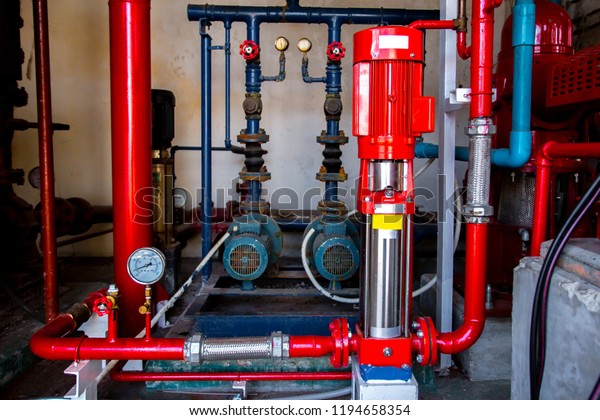
Jockey Pump Fire Pump Industrial Fire Stock Photo Edit Now
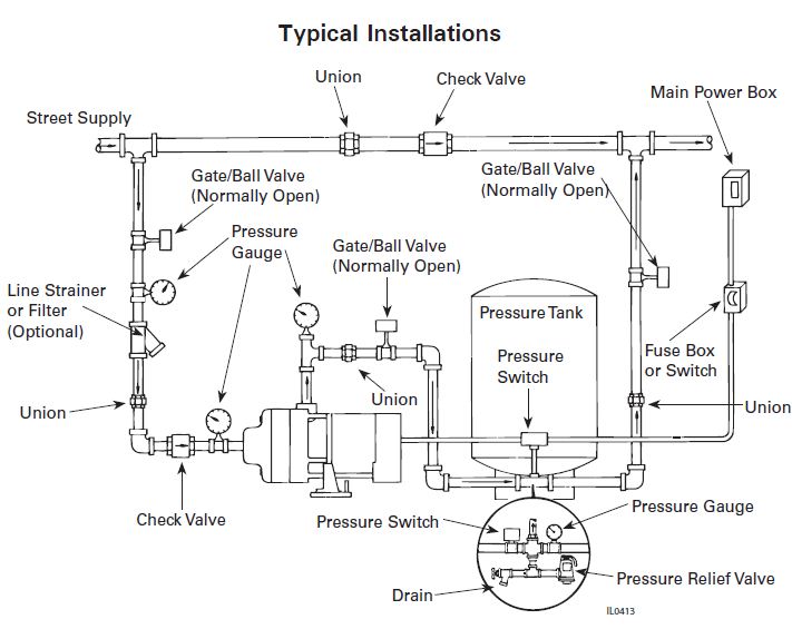
Flint And Walling Typical Piping Diagrams
Consulting Specifying Engineer Nfpa 20 Fire Pump Design
Tank Amp Pumpset Piping Amp Instrumentation Diagram Tank

Pumps Nfpa20 Presentation Latest
Instruction Installation Maintenance And Repair Manual
Fire Pumps Installation Details

Nzs 4515 Fire Sprinkler Systems For Life Safety In Sleeping
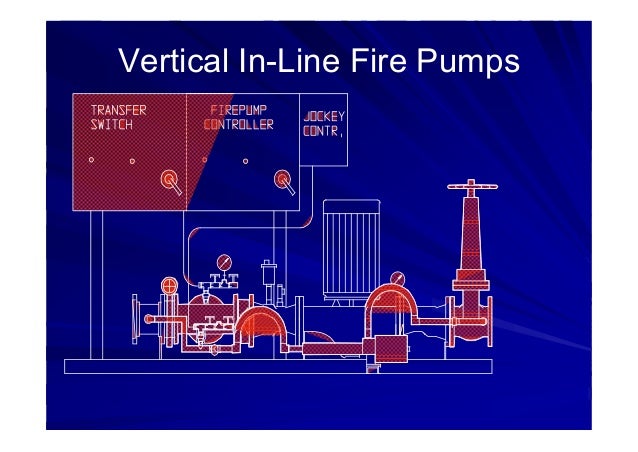
1580 Series Vertical In Line Fire Pumps Ac Fire Pump
L L L Listed

Examples Of Proper Fire Pump Equipment Installations Steven

Acse Co Ltd Pressure Sensing Piping Line Connection For

Understanding Fire Pumps Consulting Specifying Engineer

Fire Water Pump Station Design Piping Instrumentation
Fire Pump Design Calculate Appilcation For Andriod

Firefighting Pump Suction Components Nfpa 20 Fire
Jpx Series Jockey Pump Controllers Tornatech

Fire Pump Room Autocad Drawings Dwg Layouts For Pump Room

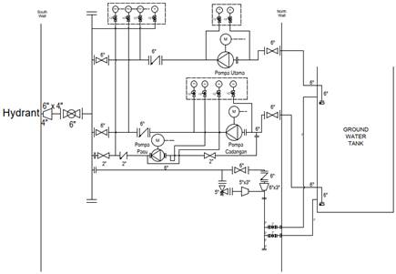
Piping Sensing Line Layout Of Fire Pump And Jockey Pump Pdf

Komponen Hydrant Dan Fungsinya Sesuai Standar Sni

Examples Of Proper Fire Pump Equipment Installations Steven
Fire Pumps
0 Response to "39 Jockey Pump Piping Diagram"
Post a Comment