39 Draw A Ray Diagram For The Following Situation Involving A Converging Lens
Jul 22, 2021 · (c) a lens holder, a screen holder and a scale. (d) a convex lens , a screen, holders for the m and a scale. Question 5: After perform in g the experiment to determ in e focal length of a convex lens by focuss in g a distant object , a teacher asked Asha to draw a j ray diagram of her experiment and show where did she place the. A draw a ray diagram for the following situation an object far from the lens involving a diverging lens. Step by step method for drawing ray diagrams. If an object is located between the focal point and converging lens the image will be. Through the center of the lens. Also draw the image on the ray diagram where the three principal rays converge.
Online Physics Curriculum. 0 m/s/s, up To explain the rules for drawing a free-body diagram. Thus far we have seen via ray diagrams that a real image is produced when an object is located more than one focal length from a converging lens; and a virtual image is formed when an object is located less than one focal length from a converging lens (i.
Draw a ray diagram for the following situation involving a converging lens
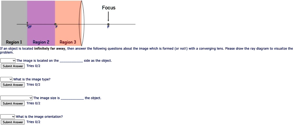
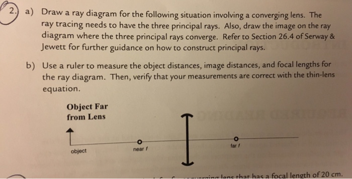
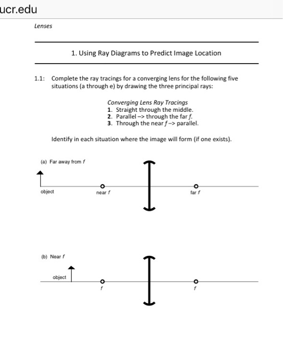
Question: a) Draw a ray diagram for the following situation involving a converging lens. The ray tracing needs to have the three principal rays. Also, draw the image on the ray diagram where the three principal rays converge. b) Use a ruler to measure the object distances, image distances, and focal lengths for the ray diagram. These three rules will be used to construct ray diagrams. A ray diagram is a tool used to determine the location, size, orientation, and type of image formed by a lens. Ray diagrams for double convex lenses were drawn in a previous part of Lesson 5. In this lesson, we will see a similar method for constructing ray diagrams for double concave. We always make sure that writers follow all your instructions precisely. You can choose your academic level: high school, college/university, master's or pHD, and we will assign you a writer who can satisfactorily meet your professor's expectations.
Draw a ray diagram for the following situation involving a converging lens. (a) Draw a ray diagram for the following situation involving a converging lens. The ray-tracing needs to have three principal rays. Also, draw the image on the ray diagram where the three principal rays converge. (b) Use the ruler to measures the object distances, image distances, and focal lengths of the ray diagram. then, verify that your. Academia.edu is a platform for academics to share research papers. A) Draw a ray diagram for the following situation (an object far from the lens) involving a diverging lens.The ray tacing needs to have the three principal rays.Also draw the image on the ray diagram where the three principle waves converge.. B) Use a ruler to measure the object distances, image distances, and focal lengths for the ray diagram. These three rules will be used to construct ray diagrams. A ray diagram is a tool used to determine the location, size, orientation, and type of image formed by a lens. Ray diagrams for double convex lenses were drawn in a previous part of Lesson 5. In this lesson, we will see a similar method for constructing ray diagrams for double concave.
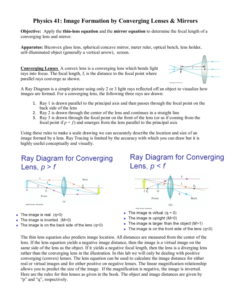
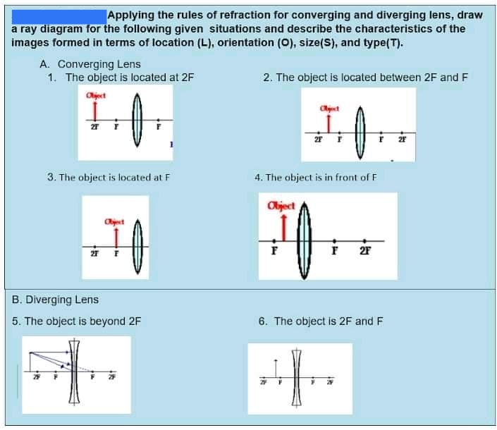
Ray Diagram for Object Located in Front of the Focal Point. In the three cases described above - the case of the object being located beyond 2F, the case of the object being located at 2F, and the case of the object being located between 2F and F - light rays are converging to a point after refracting through the lens. In such cases, a real image is formed. The graph of the derivative f?' of a function f is shown.. n what interval is f increasing?(Enter your answer using interval notation.) Lens formula is defined as the relationship between object distance (u), image-distance (v) and the focal length (f). Following is the mathematical representation of lens formula: 1 f = 1 v − 1 u 1 f = 1 v − 1 u. Where, f is the focal length of the lens. v is the distance of the image from the optical centre of the lens. Ray Diagrams for Lenses. The image formed by a single lens can be located and sized with three principal rays. Examples are given for converging and diverging lenses and for the cases where the object is inside and outside the principal focal length. The "three principal rays" which are used for visualizing the image location and size are:
A draw a ray diagram for the following situation an object far from the lens involving a diverging lens. The ray tracing needs to have the three principal rays. There is one ray of light passing through the center of the lens. 2 give me a thumbs up for this video. 11 draw a ray diagram for a diverging lens that has a focal length of 108 cm when. We offer assignment help in more than 80 courses. We are also able to handle any complex paper in any course as we have employed professional writers who are specialized in different fields of study. From their experience, they are able to work on the most difficult assignments. The following are some of the course we offer assignment help in. Power of a converging lens – The reciprocal of the focal length of the lens. Precision – An indication of the agreement among a number of measurements made in the same way (a measure of exactness). Pressure (P) – force per unit area acting on a surface. Principal axis – Line through the focal point of a lens and the center of the lens. Now, we draw the ray diagram as follows: (i) Draw a horizontal line to represent the principal axis of the convex lens. (ii) Centre line is shown by DE. (iii) Mark two foci F and F' on two sides of the lens, each at a distance of 2 cm from the lens. (iv) Draw an arrow AB of height 1 cm on the left side of lens at a distance of 5 cm from the lens.
Question: a) Draw a ray diagram for the following situation involving a converging lens. The ray tracing needs to have the three principal rays. Also, draw the image on the ray diagram where the three principal rays converge. b) Use a ruler to measure the object distances, image distances, and focal lengths for the ray diagram.
Draw a ray diagram for the following situation involving a diverging lens. 11 draw a ray diagram for a diverging lens that has a focal length of 108 cm when an object is placed 324 cm from the lenss surface. Ray diagrams for converging lens you are here trick to drawing ray diagrams for converging lens. 12 draw a ray diagram for an object.
We provide solutions to students. Please Use Our Service If You’re: Wishing for a unique insight into a subject matter for your subsequent individual research;
You are watching: Draw a ray diagram for the following situation involving a converging lens See more: R&Amp;R Gun Shows - The R Project For Statistical Computing Description of exactly how to draw ray diagrams because that diverging lenses because that grade 10 science.
A) Draw a ray diagram for the following situation ( an object far from the lens) where the three principle waves converge. B) Use a ruler to measure the object distances, image distances, and focal lengths for the ray diagram. Then verify that your measurements are correct with the thin-lens equation.
Get 24⁄7 customer support help when you place a homework help service order with us. We will guide you on how to place your essay help, proofreading and editing your draft – fixing the grammar, spelling, or formatting of your paper easily and cheaply.
Ray diagram for object located in front of the focal point. A draw a ray diagram for the following situation an object far from the lens involving a diverging lens. Posted one year ago. Through the focal point in front of the lens. A draw a ray diagram for the following situation an object far from the lens involving a diverging lens.
a) Draw a ray diagram for the following situation involving a converging lens. Subject: Physics Price: 2.85 Bought 3. Share With. a) Draw a ray diagram for the following situation involving a converging lens. The a) ray tracing needs to have the three principal rays. Also, draw the image on the ray diagram where the three principal rays converge.
Question: a) Draw a ray diagram for the following situation involving a converging lens. The ray tracing needs to have the three principal rays. Also, draw the image on the ray diagram where the three principal rays converge. b) Use a ruler to measure the object distances, image distances, and focal lengths for the ray diagram.
a Draw a ray diagram for the following situation involving a converging lens. The two arms of a Utube are not identical one having 2... A new car manufacturer advertises that their car can go quotfrom zero to sixty in 8 squot ...
Convex (converging) and concave (diverging) lenses are drawn as, V W To understand image formation we use ray diagrams. Here is an example for aconvex lens: F The image of the top of the object is formed where the light rays cross. In a perfect lens all the rays from a point on the object will meet at one other point - so we only need to draw.
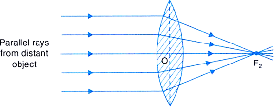
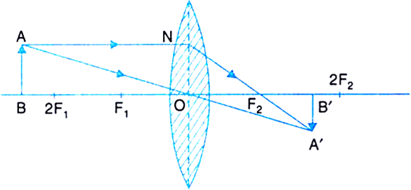
In order to draw a ray diagram, take two rays of light from the object. Ray 1: A ray parallel to the principal axis. Ray 2: A ray passing through the pole . After reaching the lens, ray 1 will bend and pass through the focus. Ray 2 will pass without any deviation. The two rays will converge at a point and recreate an image.
A draw a ray diagram for the following situation an object far from the lens involving a diverging lensthe ray tacing needs to have the three principal raysalso draw the image on the ray diagram where the three principle waves converge. Parallel to the principal axis of the lens. From the tip of the object arrow.
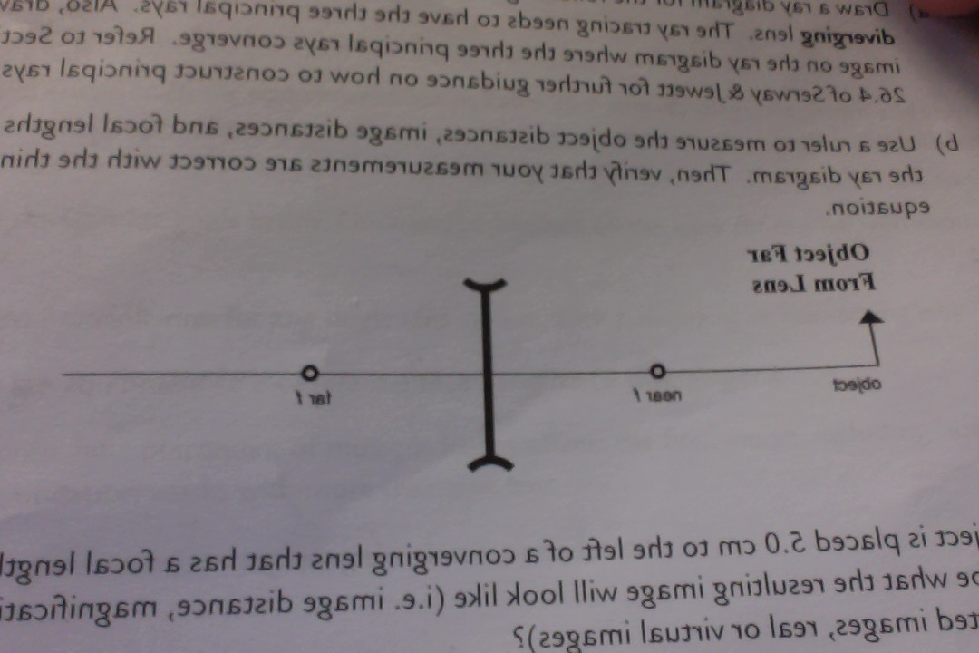
A) Draw a ray diagram for the following situation ( an object far from the lens) involving a diverging lens. The ray tracing needs to have the three principal rays. B) Use a ruler to measure the object distances, image distances, and focal lengths for the ray diagram. Then verify that your measurements are correct with the thin-lens equation.
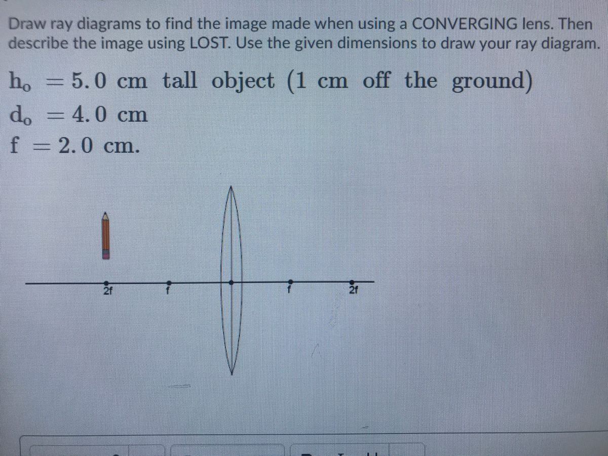
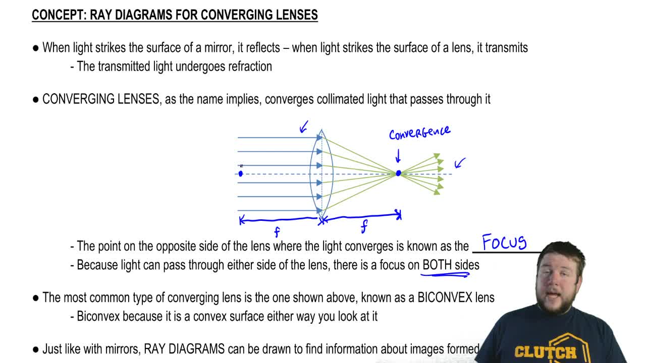
To explain how to draw the diagrams, there are two key things to remember. 1 A converging lens refracts the light so that any ray of light parallel to the principal axis (the thick horizontal line) is turned to pass through the focal point. Rays of light parallel to the principal axis are all refracted through the focal point.
Get 24⁄7 customer support help when you place a homework help service order with us. We will guide you on how to place your essay help, proofreading and editing your draft – fixing the grammar, spelling, or formatting of your paper easily and cheaply.
A lens is considered to be thin if its thickness t is much less than the radii of curvature of both surfaces, as shown in.In this case, the rays may be considered to bend once at the center of the lens. For the case drawn in the figure, light ray 1 is parallel to the optical axis, so the outgoing ray is bent once at the center of the lens and goes through the focal point.
We always make sure that writers follow all your instructions precisely. You can choose your academic level: high school, college/university, master's or pHD, and we will assign you a writer who can satisfactorily meet your professor's expectations.
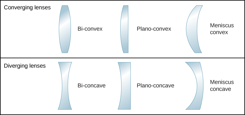
(The axis is defined to be a line normal to the lens at its center, as shown in Figure 1.) Such a lens is called a converging (or convex) lens for the converging effect it has on light rays. An expanded view of the path of one ray through the lens is shown, to illustrate how the ray changes direction both as it enters and as it leaves the lens.
Draw a ray diagram for the following situation (an object far from the lens) involving a diverging lens. The ray tracing needs to have the three principal rays. Also, draw the image on the ray diagram where the three principal rays converge. Refer to Section 26.4 of Serway & Jewett for further guidance on how to construct principal rays.
ALL YOUR PAPER NEEDS COVERED 24/7. No matter what kind of academic paper you need, it is simple and affordable to place your order with Achiever Essays.
When drawing ray diagrams for lenses, there are a few more important things to note. Firstly, lenses can either be drawn as lens shapes or as lines with arrows on them. The convention is that a diverging lens has inwards pointing arrows and a converging lens has outwards pointing arrows, mimicking the shapes of the lenses.
About Indiana Jones. Indiana Jones, also known by his full name, Dr. Henry Walton Jones Jr., spent most of his childhood traveling the world with his parents and meeting famous historical figures. As an adult, Indiana was a professor of ancient civilizations, although he would often embark on adventures to recover lost or stolen artifacts.













0 Response to "39 Draw A Ray Diagram For The Following Situation Involving A Converging Lens"
Post a Comment