37 Single Wire Alternator Wiring Diagram
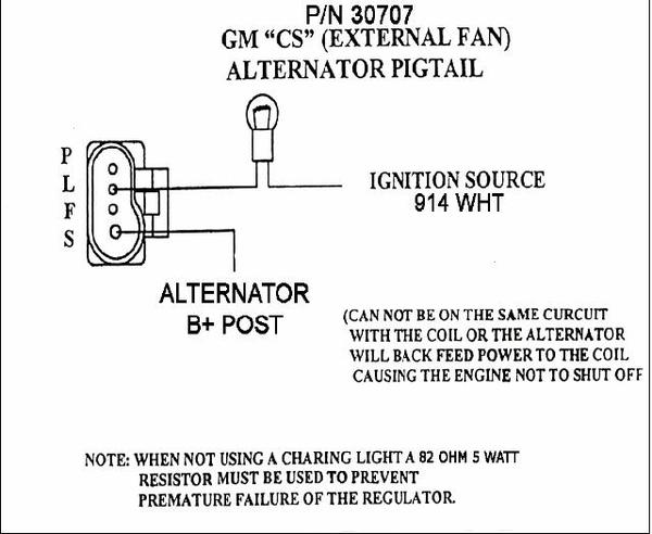
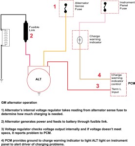
Jul 24, 2021 · Interactive electrical wiring diagram for DIY camper van conversion (skoolie, RV). Hover your mouse / click on any product to learn more. Nov 23, 2013 · GM alternator wiring GM alternator wiring. GM has many different alternators and each has its own alternator wiring diagram and alternator symptoms. One of the key differences is how the internal voltage regulator determines charge rate. Does it check the vehicle’s voltage internally or from an outside source? The PDF shown here is for a GM.
Diese Webseite verwendet Affiliate-Links. Erfolgt Single Wire Alternator Wiring Diagram eine Bestellung oder ein Kauf über diese Links, erhält trusted eine Provision vom jeweiligen Anbieter. Das ermöglicht es uns, Ihnen unseren Service und unsere Inhalte kostenlos zur Verfügung zu stellen.
Single wire alternator wiring diagram
Note: the alternator charge wire routes direct to the battery and not through any switch connection, the alternator will not operate correctly if not connected direct to battery or directly through the ammeter. Note: the wiring that comes with our kits should be used as it is sized to handle the amperage. 2 Wire Alternator Wiring Diagram - 2 wire alternator wiring diagram, ac delco 2 wire alternator wiring diagram, bosch 2 wire alternator wiring diagram, Every electric arrangement is made up of various distinct pieces. Each part ought to be set and connected with different parts in particular manner. How do I wire my marine alternator? Many alternators require ignition voltage to initiate charging. You must verify that all required connections are connected to the proper terminal and have the correct voltage in order for the alternator to operate properly. Below you will find the most common alternator circuits used on marine applications.
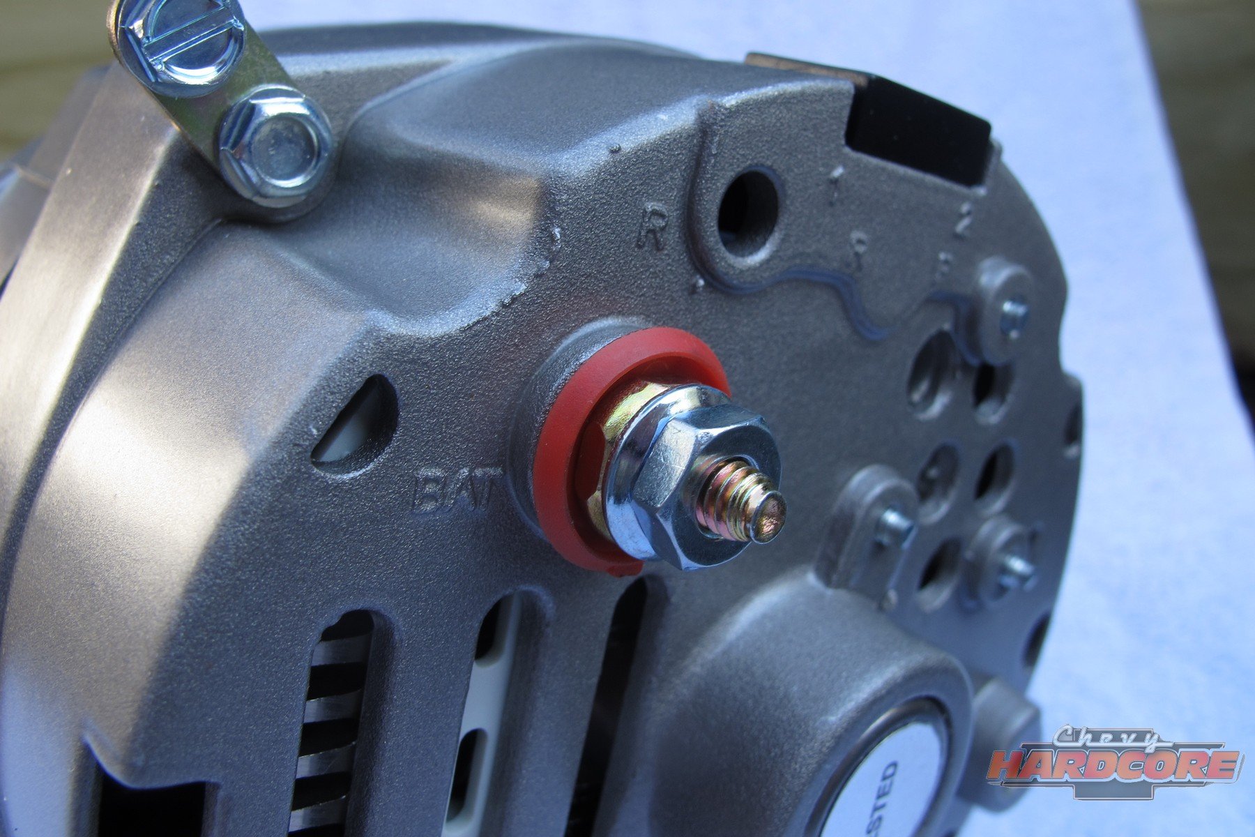
Single wire alternator wiring diagram. WIRING INSTRUCTIONS GM SI Alternator (One Wire or OE Hookup) Tech Dept. (630) 957-4019 Tech@powermasterperformance Replaces these OEM Alternators GM 10DN Externally Regulated GM 10SI Internally Optional Charge Indicator Light Function: Your Powermaster Alternator is designed to work as a 1 wire without any connections to the plug in. The Self-Exciting Alternator makes no need for Alternator Wiring Diagram The Self-Exciting alternator is an alternator that has a special voltage regulator that doesn't need an ignition wire to activate it.This is usually based on a chevy alternator type and only requires a battery wire connected to the battery terminal. Oct 21, 2018 - In Alternator Diagram Wiring, best images In Alternator Diagram Wiring Added on Wiring Diagram - floraoflangkawi Delco Remy alternator, and so except for wiring, the up-grade is a "bolt-on. Basic wiring schematic with a GM 10Si alternator. From a Farm Tractor Web Site. Original Amphicar wiring schematic with a. How to Wire 120V & 240V Main Panel? Breaker Box Installation; How to Wire 240V, 208V & 120V, 1 & 3-Phase, High Leg Delta Main Panel? These are the general setup and may vary (i.e. the further wiring depends on the appliance requirement) e.g. neutral wire may be needed in both single phase and three phase 208V circuits as shown in the fig below.
2 Wire Alternator Wiring Diagram - 2 wire alternator wiring diagram, ac delco 2 wire alternator wiring diagram, bosch 2 wire alternator wiring diagram, Every electric arrangement is made up of various distinct pieces. Each part ought to be set and connected with different parts in particular manner. Chevy One Wire Alternator Wiring – Wiring Diagram Detailed – One Wire Alternator Wiring Diagram. Wiring diagram also gives useful ideas for tasks which may need some added equipment. This book even includes suggestions for additional provides that you could want to be able to end your projects. 9 - If installing an alternator with OEM wiring connections, reconnect alternator wires and battery ground cable. If installing a 1-wire alternator, see wiring instructions at upper right. 10 - Make sure battery is fully charged before starting engine. 11 - Reconnect the ground cable, start the engine and using a VOM meter, verify that the. Wiring Diagram Single Phase Motors. on off with 6 pin quora 3 control using plc ladder logic tutorials point sot reversing plcs net interactive q drum to wire mgr electrical controller dpdt wiring huimultd electronic systems facebook clear project box... Nippon Denso Alternator Wiring Diagram.
3 4l gm alternator wiring wiring diagram schema. how to install a 1 wire gm alternator it still runs installing a one wire gm alternator makes the process of adding an alternator to a vehicle originally equipped with a generator very simple one wire alternators are also used by people in the performance car field to help make the car lighter as there are fewer wires to add weight to the. One Wire Alternator. More generator alternator conversion best way to a 1 wire gm single wiring mg changing from 2 one the cj2a catalog help page farmall cub ls swap information question 1947 official cvf install round how keeps draing my please chevy with internal regulator cs130 cs144 3 diagram frequently asked questions faq voltage regulation 101 1997 saturn problem charging system vs. Gm Single Wire Alternator Diagram - Wiring Diagrams Hubs - One Wire Alternator Wiring Diagram Chevy. Wiring Diagram not only provides comprehensive illustrations of what you can do, but also the procedures you ought to follow although performing so. Not only is it possible to find different diagrams, however, you may also get step-by-step. Mecc Alte Generator Wiring Diagram. Aligning the drive motor to the B3B14 alternator. Aligning winding as shown in the figures beside and in the wiring diagrams. Code: en_GB. generator can be wired in several configurations to produce 3-phase or split single phase current. MeccAlte NPE32 E/4. wire terminal block diagrams.
Single Wire Alternator Wiring Diagram. Print the wiring diagram off plus use highlighters to trace the signal. When you make use of your finger or perhaps the actual circuit with your eyes, it is easy to mistrace the circuit. 1 trick that We 2 to printing a similar wiring plan off twice. Upon one, I'll trace the current movement, how it.
1961 Cub Cadet Original. Circle of Safety: Y. Re: 1 wire alternator wiring diagram. Postby Slim140 » Mon May 15, 2017 12:34 pm. In case anyone is wondering here's the best true one wire alternator. It can be ran straight to the battery via the amp gauge and won't drain it. It's $71.39 with free shipping.
Single Wire Alternator Diagram – wiring diagram is a simplified conventional pictorial representation of an electrical circuit. It shows the components of the circuit as simplified shapes, and the capacity and signal friends together with the devices. A wiring diagram usually gives opinion approximately the relative incline and understanding.
The diagram above is the 5 pin relay wiring diagram. There are different kinds of relays for different purposes. It can be used for various switching. Relay can be the best option to control electrical devices automatically. 5 pin is compromised of 3 main pins and an SPDT (single pole double throw).
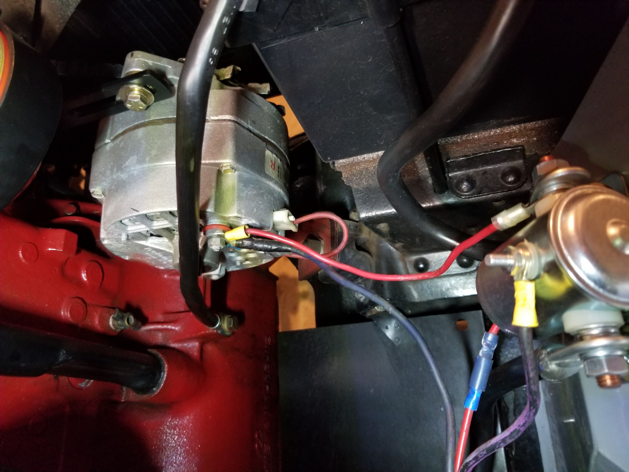
This video shows you how to wire a Single Wire Alternator on Tractors.We are showing this example on an MF 35 Deluxe Tractor but the same wiring will work on...
Gm Alternator Wiring Diagram Internal Regulator - As soon as you learn a couple of basics they are really very easy to study, though a car wiring diagram may seem daunting. The first thing you will require to discover is what every single icon means. To read through it, initially establish the circuit in question, then beginning from its terrain reference position, stick to it following that.
This connector is manufactured so it may be inserted into the connector socket on the alternator one way only. If you are able to look at a manufacturer's diagram of the alternator's connectors, the wire that slides over Pin 1 of the alternator leads to the positive (+) connection on the vehicle's battery and senses voltage.
Feb 22, 2009 · Well, here are a few more wiring diagrams for Jeep Wrangler – this time for the Jeep YJ series years 1987 to 1994. The PDF includes ‘body’ electrical diagrams and Jeep YJ electrical diagrams for specific areas like: air conditioning units, typical jeep charging unit wiring diagrams, typical emission maintenance reminder wiring diagrams, front end lighting wiring diagrams and switches.
Single Wire Alternator Wiring Diagram - wiring diagram is a simplified up to standard pictorial representation of an electrical circuit. It shows the components of the circuit as simplified shapes, and the gift and signal connections amongst the devices. A wiring diagram usually gives recommendation nearly the relative slope and settlement of.
Single Phase 120V/230V Distribution and Panel Board Wiring in Home. Single Phase wiring installation is the most common wiring in residential buildings. In Single Phase supply (230V in UK, EU and 120V & 240V in the US & Canada), there are two (one is Line (aka Phase, Hot or Live) and the other one is Neutral) incoming cables from the utility poles to the kWh energy meter and then directly.
1 wire alternator wiring diagram. If installing a 1 wire alternator see wiring instructions at upper right. Wiring instructions gm si alternator one wire or oe hookup tech dept. Here is a picture gallery about 1 wire alternator wiring diagram complete with the description of the image please find the image you need.
Feb 03, 2019 · 02.03.2019 02.03.2019 7 Comments on Dometic 3 Wire Thermostat With Controll Kit Wiring Diagram Dometic RV Air Conditioner Single Zone LCD Thermostat and Control Kit Yes it will replace the standard analog thermostat. this one only uses three wires. the old control Panel and you will see what wires are what on the wiring diagram.
Alternator Exciter Wire Diagram | Wiring Library - Alternator Exciter Wiring Diagram. The diagram offers visual representation of an electrical arrangement. However, the diagram is a simplified variant of this structure. It makes the process of assembling circuit simpler. This diagram provides information of circuit's components in addition.
April 15, 2020 · Wiring Diagram. by Anna R. Higginbotham. one wire alternator wiring diagram - You will need an extensive, professional, and easy to comprehend Wiring Diagram. With this kind of an illustrative guidebook, you'll have the ability to troubleshoot, stop, and total your projects easily.
Alternator Wiring Kit 555 -10510 100 Amps 8 gauge 150 Amps 6 gauge 200 Amps 4 gauge It is very important to use the correct wire size to connect the alternator to the battery. A wire size too small can allow the wire to overheat, melt the insulation and cause a fire or worse. Dependin g upon the maximum output of the alternator, use the.
Ford alternator wiring diagram internal regulator. Among all the Ford alternator wiring diagrams above, this is the most complicated one. It consists of ignition switch, fuse panel, engine compartment relay box, instrument cluster and many more. It requires advanced knowledge to fix an alternator with this diagram.
Below given are some alternator wiring diagrams that are used for different purposes.Let's have a look at their connections. 3 Wire Alternator Wiring Diagram Source: www.carparts This is a three-wire alternating wiring diagram showing the connections between the different components of a circuit.
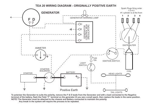
Taking all the above into account, here is how I scribbled up my copy of that wiring diagram, try it yourself on your wiring diagram, it will start to make a lot of sense and soon, you'll be designing your own tractor's conversion. Recap: 1. The alternator wire will be a number 10 wire run to the ammeter. Must reverse the poles on the ammeter.
Wiring Diagrams : One Wire Alternator Conversion Kit Delco Remy, size: 800 x 600 px, source: www.sconseteer . Below are several of the top drawings we get from various sources, we really hope these images will serve to you, and also ideally very pertinent to just what you desire regarding the Single Wire Alternator Conversion Diagram is.
Alternator Specs In addition to wiring diagrams, these guides also provide information on Alternator Identification and procedures for an engine replacement with a new Briggs & Stratton engine that utilizes a different style alternator (output connector).
WIRING INSTRUCTIONS GM SI Alternator (One Wire or OE Hookup) Tech Dept. (630) 957-4019 Tech@powermasterperformance Replaces these OEM Alternators GM 10DN Externally Regulated GM 10SI Internally Optional Charge Indicator Light Function: Your Powermaster Alternator is designed to work as a 1 wire without any connections to the plug in. The
How do I wire my marine alternator? Many alternators require ignition voltage to initiate charging. You must verify that all required connections are connected to the proper terminal and have the correct voltage in order for the alternator to operate properly. Below you will find the most common alternator circuits used on marine applications.
Typical Trailer Wiring Diagram and Schematic. The 2 above wire diagrams fit the needs of most trailers. The first image shows a single axle trailer, and the second, wiring for Tandem Axles. Only the (blue) brake and (white) ground wires are different. You can expand the same conditions for more axles.
Skip the “please review my diagram” on online forums or Facebook groups. Our wiring diagram is designed with flexibility in mind. Any sub-system can be deleted (monitor, inverter, solar, alternator, shore) or added later. Keep a copy at all time in your van so you, or someone else, can refer to it if anything happen.
Common Delco SI Series Alternator Wiring Diagram. by David Smith Sep 22, 2016. We are commonly asked how to wire the Delco SI series alternators upon maintenance or upgrading from an older generator. While this series of unit often runs as a self exciting one wire, agricultural applications also used 3 wire connections to the alternator.
Note: the alternator charge wire routes direct to the battery and not through any switch connection, the alternator will not operate correctly if not connected direct to battery or directly through the ammeter. Note: the wiring that comes with our kits should be used as it is sized to handle the amperage.
Understanding the Alternator • Four wires connect the alternator to the rest of the charging system. • B is the alternator output wire that supplies current to the battery. • IG is the ignition input that turns on the alternator/regulator assembly. • S is used by the regulator to monitor charging voltage at the battery.








0 Response to "37 Single Wire Alternator Wiring Diagram"
Post a Comment