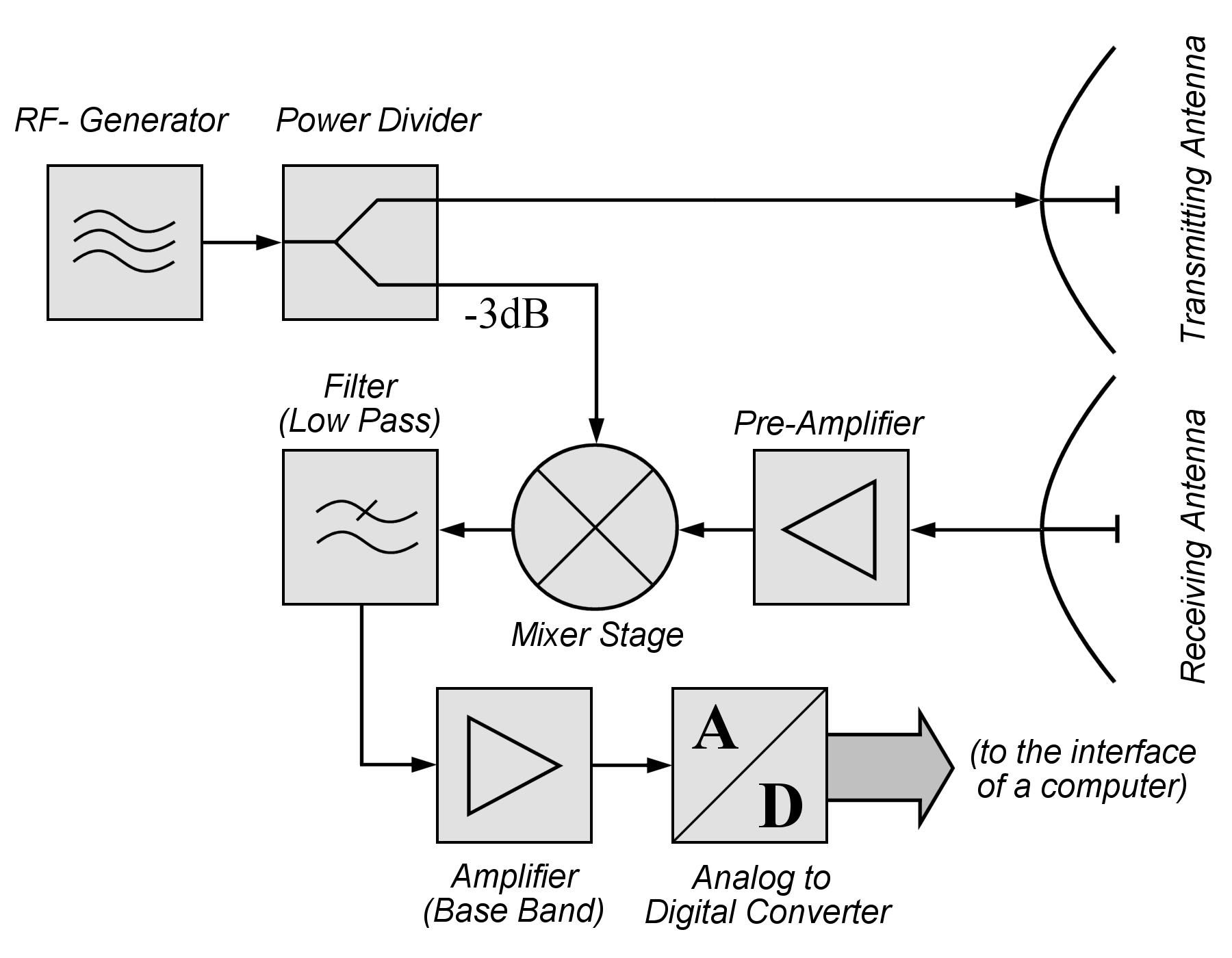
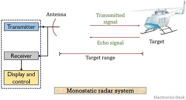
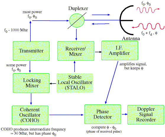
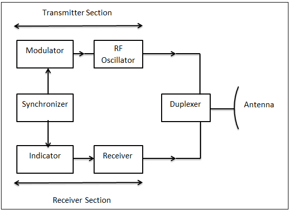
43 Radar System Block Diagram
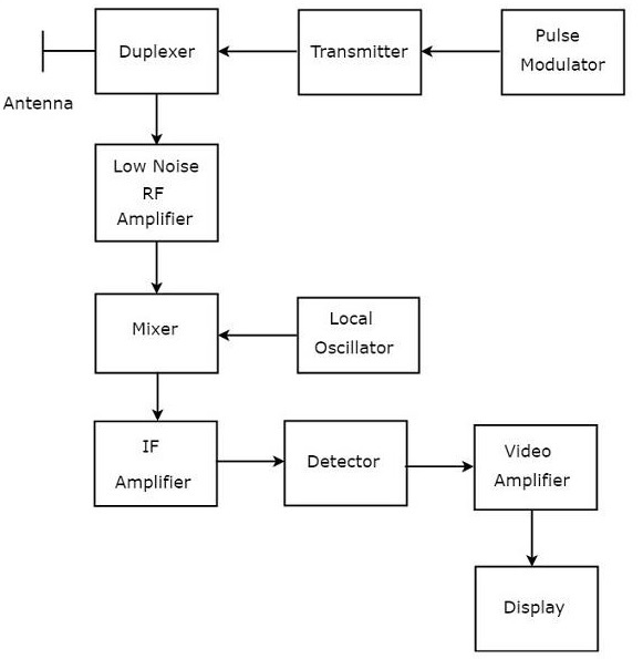
-- Figure 3-11: Radar System Block Diagram -- Receiver Transmitter The receiver transmitter contains all of the circuitry to gener-ate the RF pulse and to listen for its return. It sends this data to the display in many different ways, depending on the system.-- Figure 3-12: Block Diagram of Pulse Radar. Pulse Radar uses single Antenna for both transmitting and receiving of signals with the help of Duplexer. Following is the block diagram of Pulse Radar −. Let us now see the function of each block of Pulse Radar −. Pulse Modulator − It produces a pulse-modulated signal and it is applied to the Transmitter.
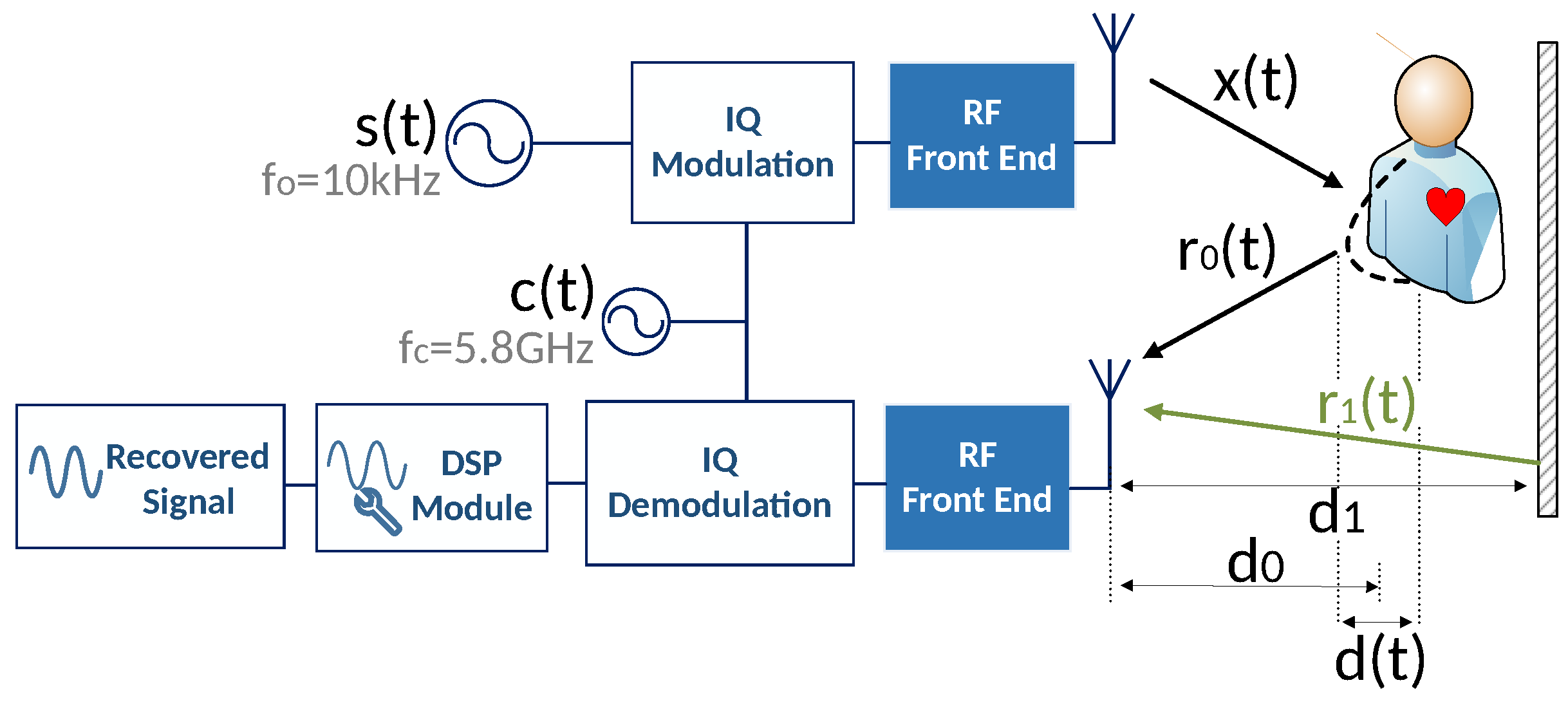
The baseband in-phase (I) and quadrature-phase (Q) signals are digitized using a pair of A/D converters The synchronous detector is also referred to as a quadrature channel receiver, quadrature detector, I/Q demodulator, or coherent detector. Well, If I turn the whole construct by 90°.
Radar system block diagram
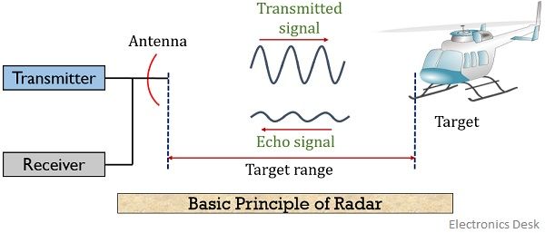
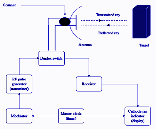
Block Diagram of Radar System. The typical block diagram of radar system is shown in Figure. The essential elements of a radar system are: The timer device is used for coordinating the action of the transmitter, receiver, and indicator, to ensure synchronized operation.. Radar Principle. The electronic principle on which radar operates is very similar to the principle of sound-wave reflection. If you shout in the direction of a sound-reflecting object (like a rocky canyon or cave), you will hear an echo. If you know the speed of sound in air, you can then estimate the distance and general direction of the object. Content: Radar System. History; Principle; Block Diagram; Applications; History. Radar was invented for military purpose before world war II in order to secretly detect the presence of unknown objects. Initially, the transmitting tubes were not that much powerful thus worked at a very low frequency of about 60 MHz.. But further development in the field and use of magnetrons has extended the.
Radar system block diagram. Content: Radar System. History; Principle; Block Diagram; Applications; History. Radar was invented for military purpose before world war II in order to secretly detect the presence of unknown objects. Initially, the transmitting tubes were not that much powerful thus worked at a very low frequency of about 60 MHz.. But further development in the field and use of magnetrons has extended the. In this video, i have explained RADAR Tracking with following aspects.1. RADAR Tracking2. Basics of RADAR Tracking3. Parameters of RADAR Tracking4. Block Dia... Radar Systems Course 1 MTI 1/1/2010 IEEE AES Society Radar Systems Engineering. Block Diagram of Radar System Antenna. Propagation. Medium. Target. Radar. Cross. Section. Transmitter. General Purpose Computer. Tracking.... Block Diagrams of CW and Pulse Radars. Basic Continuous Wave (CW) Radar. Basic Pulse Radar. CW. Transmitter. T/R. FIGURE 1.1 An example of a Real-Time system Figure 1.2 shows a block diagram of an air traffic control system. The system displays aircraft tracks obtained from radar sites. It accepts radar data on tracks locations, and operator inputs to establish tracks or to change the location of a specified track. The system periodically extrapolates
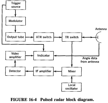
The radar antenna transmits radio wave pulses that bounce off any object in their path. The object returns a portion of the wave received by the receiver which is in line of sight with the transmitter. This Arduino RADAR project aims to achieve a radar system prototype based on an Arduino board, capable of detecting stationary and moving objects. Pasternack's library RF and microwave block diagram are designed to provide engineers and designers with examples of common RF systems schematics while illustrating the RF products and where they fit into the system's design.. Radar System. Radar Chip-Set. 13.75 - 14.5 GHz VSAT Radio. 28 - 31.5 GHz VSAT Radio. 71 - 81 GHz E-Band Radio. Pulsed Radar System Block Diagram: A very Pulsed Radar System Block Diagram set was shown in Figure 16-1. A more detailed block diagram will now be given, and it will then be possible to compare some of the circuits used with those treated in other contexts and to discuss in detail those circuits peculiar to radar. Block diagram and description: The sub-level block diagram shown in Figure 3 displays the EW digital radar receiver in more detail than Figure 1. Block 1 mixes an analog RF signal with an analog LO frequency from Block 2 to produce an analog intermediate frequency (IF). The IF signal is sampled by Block 3 to be processed by Block 4. In addition, Block 4 controls the LO.
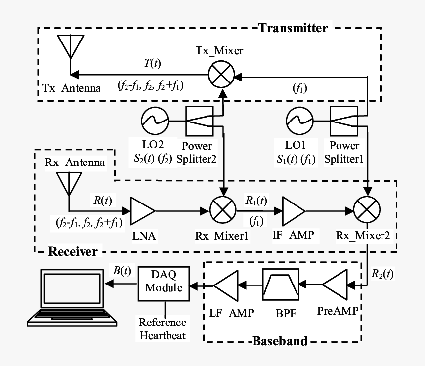
that the Vayyar EVK was the most promising candidate radar system. You can see a block diagram of the system in Figure 2 below. SDDEC18-18 6 Figure 2 Our back-up (and chosen) plan was to use a radar system only for object detection and to use a camera for object identification. The radar system would provide the range, angle, and power of the Radar Principle. The electronic principle on which radar operates is very similar to the principle of sound-wave reflection. If you shout in the direction of a sound-reflecting object (like a rocky canyon or cave), you will hear an echo. If you know the speed of sound in air, you can then estimate the distance and general direction of the object. Radar Block Diagram • This receiver is a superheterodyne receiver because of the intermediate frequency (IF) amplifier. (Similar to Figure 1.4 in Skolnik.) • Coherent radar uses the same local oscillator reference for transmit and receive. The question is 'In this block diagram of a radar system, what does each of the letters represent? Thanks in advance A320. If the British Empire and its Commonwealth last for a thousand years, men will still say, 'This was their finest hour.' USER_MINI_PROFILE. A320ajm. Posts: 587; Joined: Sat May 20, 2006 11:57 pm
Block Diagram of Radar: The transmitter can be a power amplifier such as klystron, travelling wave tube etc. It can also be a power oscillator such as magnetron. The radar signal is produced at low power by a waveform generator which is then amplified by the power amplifier. The output of the power amplifier is delivered to the antenna by a.
Radar System Modeling. This example shows how to set up a radar system simulation consisting of a transmitter, a channel with a target, and a receiver. For the Aerospace Defense industry, this is an important multi-discipline problem. RF Blockset™ is used for modeling the RF transmitter and receiver sections.
Figure 1: Universal Block Diagram of Pulse Radar This block diagram may be used for your own lessons but there are no block labels in the animation and there is no background image (landscape). These block labels can be placed in an own layer over the animation in e.g. MS-PowerPoint with text boxes in your own language version.
Block Diagram Of The 2 4 Ghz Doppler Radar Integrated On Printed Scientific. One Chip Radar Detection Circuit Measuring And Test Diagram Seekic Com. Block Diagram Of The Radar Sensor Circuit Uses A Branch Line Power Scientific. Projects Build A Small Radar System Capable Of Sensing Range Doppler And Synthetic Aperture Imaging Mit Opencourseware.
Rendezvous Radar System Block Diagram. TRANSPONDER ANTENNA. The transponder utilizes two antenna systems, (Figure Below) a dipole antenna array and two dual spiral antennas. The selected antenna system is connected to the transponder by an antenna select switch. The dipole antenna array is located on an extendable boom which is retracted until.
System Block Diagram: Figure 2. Block Diagram of Radar System. Figure 2 represents the system's block diagram. Here, it can be seen how the work flow in this radar system. The sensor is going to sense the obstacle and determine the angle of incident and its distance from the radar. The servo motor is constantly rotating to and fro, hence
block diagram of a pulse radar in chapter 1 (fig. 1-4). Relate the function blocks in figure 1-4 to the basic units. off-the-shelf radar system was not designed to use
operation of the radar. The functional block diagram (fig 2) depicts the eight major systems of the TTR which are: synchronizing system, transmitting system, RF (monopulse duplexer) and antenna system, receiver system, ranging system, antenna position system, presentation system, and RF and IF testing system. A
Block Diagram Showing CW RADAR Radar Range Equation. There are different kinds of versions available for the radar range equations. Here, the following equation is one of the fundamental types for an only antenna system. When the object is assumed to be in the middle of the antenna signal, then the highest radar detection range can be written as
The below figure represents a typical system for traffic radar. For multi-piece radars the antenna is usually separate from the rest of the electronics. Figure D-1-- Radar Block Diagram. Antenna GAIN Antenna gain (G) can be expressed in terms of wavelength (Lambda) and effective antenna area (A e). Effective antenna area is physical area (A.
RADAR SYSTEM BLOCK DIAGRAM. Circulator Receiver Protector Synchronous I/ Q Detector ADC and Signal Processor Display Pulse Generator Mixer Mixer Coupler Coupler Oscillator LO PA Radar LNA. ISO 9001 : 2008 Registered Pasternack Enterprises, Inc. P.o. Box 16759, Irvine, CA 92623 Phone: (866) 727-8376 or (949) 261-1920 Fax: (949) 261-7451
Basic Radar Block Diagram. A basic radar block diagram is shown in Fig. 1. The pulse repetition frequency is controlled by the timer (also called trigger generator or synchronizer) in the modulator block.The pulse-forming circuits in the modulator are triggered by the timer and generate high-voltage pulses of rectangular shape and short duration.
Block Diagram of Radar System. The typical block diagram of radar system is shown in Figure. The essential elements of a radar system are: The timer device is used for coordinating the action of the transmitter, receiver, and indicator, to ensure synchronized operation..
2 System Overview 2.1 Block Diagram Figure 1. SRR System Block Diagram 2.2 Highlighted Products 2.2.1 AWR1642 Single-Chip Radar Solution The AWR1642 is an integrated single-chip, frequency modulated continuous wave (FMCW) sensor capable of operation in the 76 to 81 GHz frequency band. The device is built with TI's low-power, 45-nm
Radar range equation for search (S/N = signal to noise ratio) • S/N of target can be enhanced by – Higher transmitted power P. av – Lower system losses L – Minimize system temperature T. s. R k T L P A t S/N. s 4 av e s. Ω = 4π σ. The design of radar transmitter/receiver affects these three parameters directly. P. av = average power.
MIT IAP 2011 Radar Instructions-1. GLC 8/28/2012 . MIT Lincoln Laboratory . MIT IAP 2011 Laptop Based Radar: Block Diagram, Schematics, Bill of Material, and Fabrication Instructions* Presented at the 2011 MIT Independent Activities Period (IAP) *This work is sponsored by the Department of the Air Force under Air Force Contract #FA8721-05-C-0002.
Details about the overall block diagram for the superheterodyne radio receiver: major circuit blocks, functions, overall operation, & electronic circuit design considerations. The superhet radio receiver is used in many forms of radio broadcast reception, two way radio communications and the like. It is useful to have an understanding of the.
UWB Radar working operation. The radar system which uses signal having UWB characteristics is known as UWB radar. The UWB signal occupies much wider frequency compare to conventional radar system. Moreover it uses very low power which is less than thermal noise signal power. The figure depicts typical UWB transmitter and receiver block diagram.
The block diagram of the FMCW Radar looks similar to the block diagram of CW Radar. It contains few modified blocks and some other blocks in addition to the blocks that are present in the block diagram of CW Radar. The function of each block of FMCW Radar is mentioned below.












0 Response to "43 Radar System Block Diagram"
Post a Comment