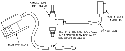
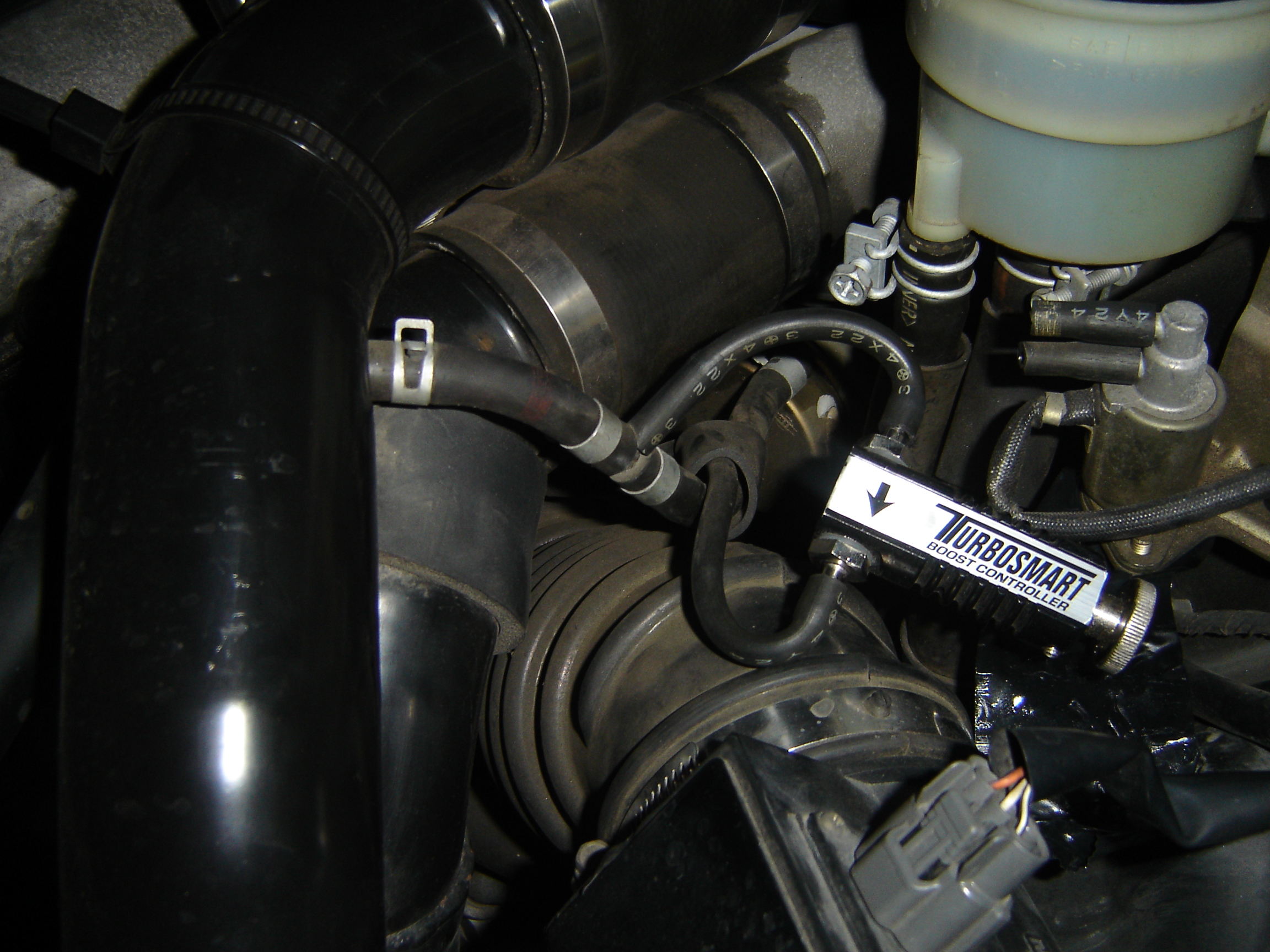
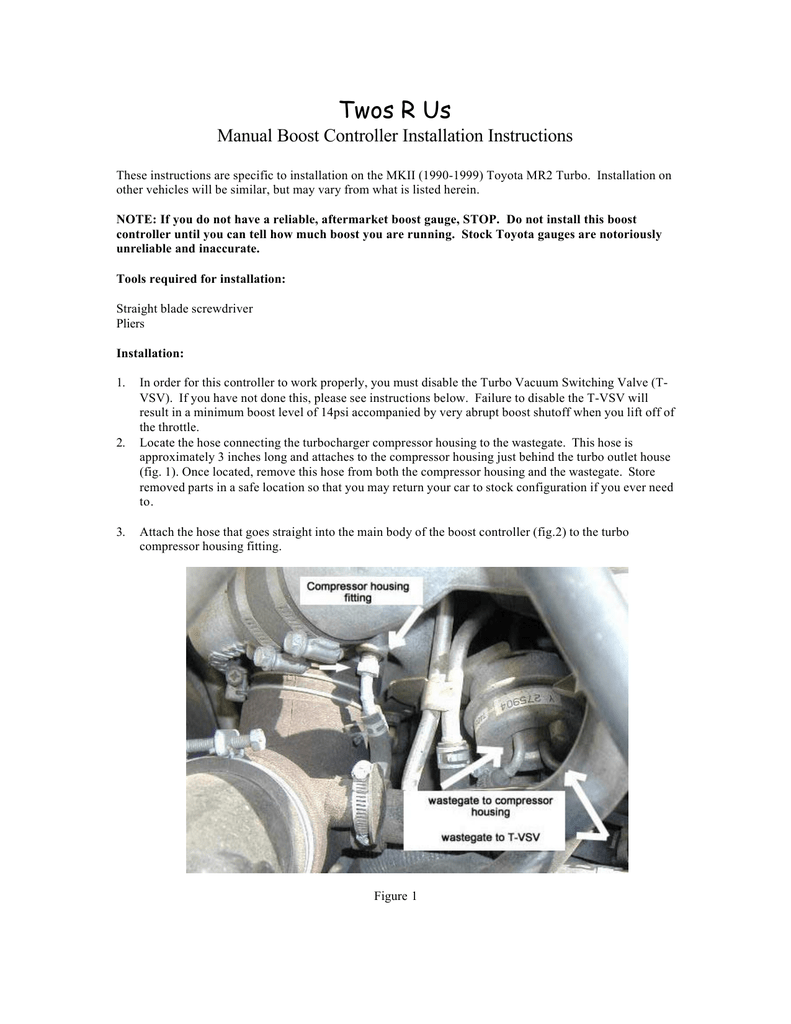
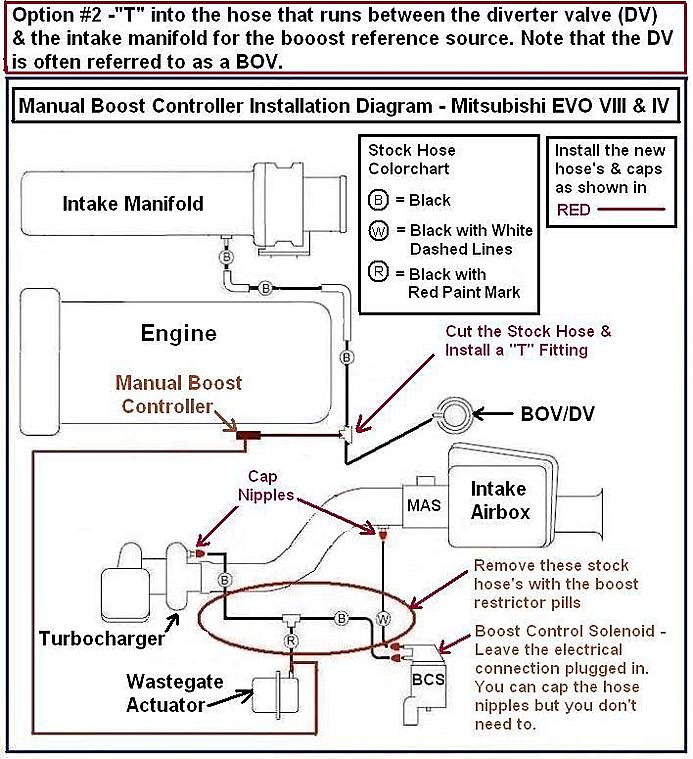
43 Manual Boost Controller Diagram
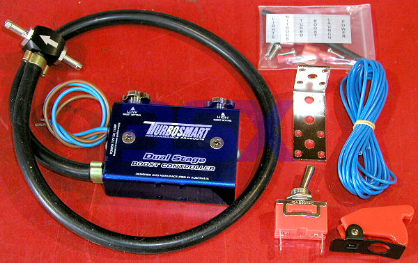
Manual boost control is achieved by bypassing the ECU controlled Solenoid Valve to have total control via a Needle Valve from inside the vehicle. The Needle Valve controls the rate of turbo spool and the TDi Dawes Valve controls maximum boost to a moderate 18psi at full throttle and 4000rpm. This system eliminates boost spikes to over 25psi as. Turbosmart product fitting Instructions provide important information regarding products, spring charts, tech drawings and graphs.
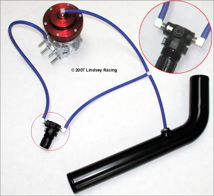
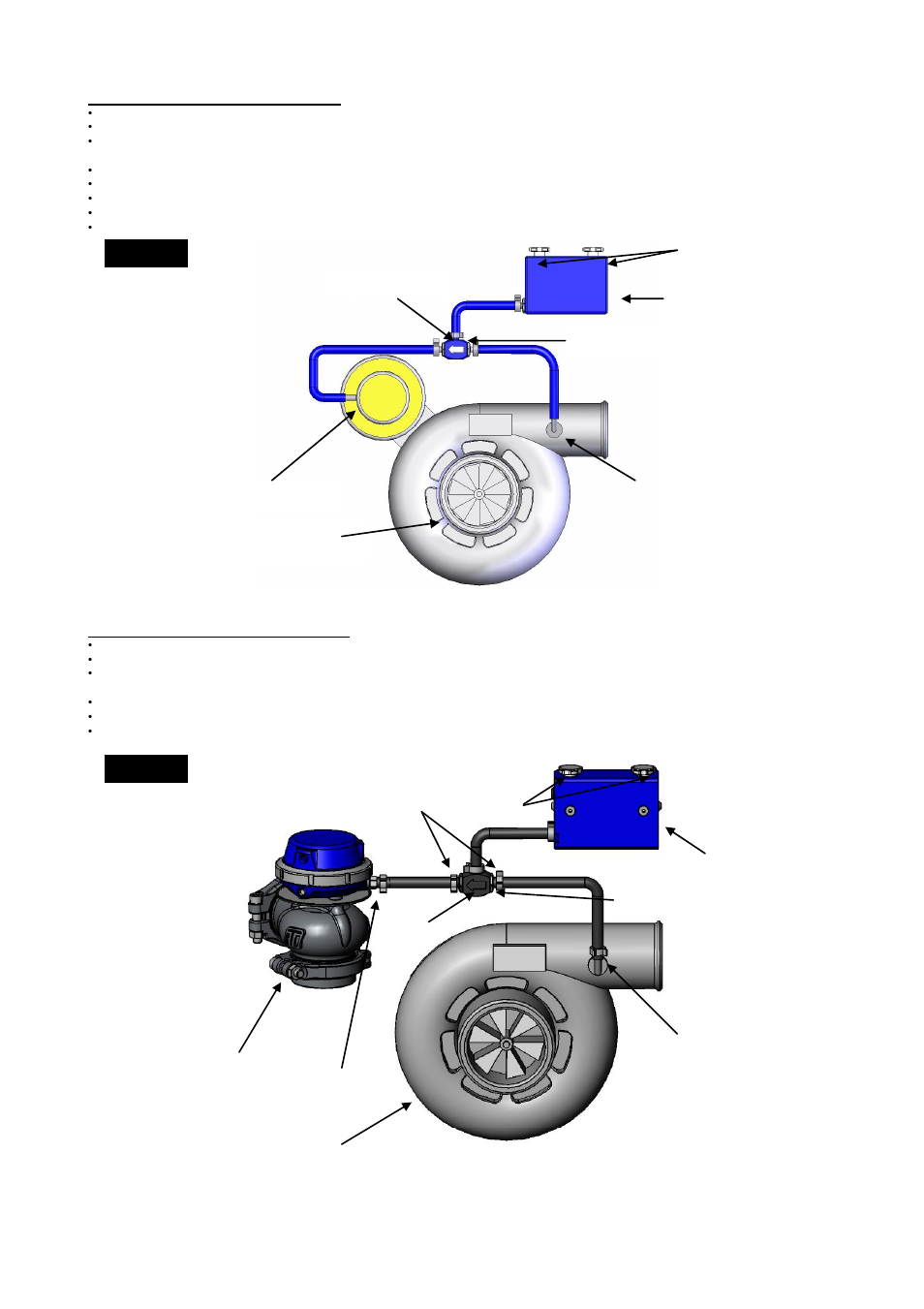
MANUAL BOOST CONTROLLER w/DUAL PORT WASTEGATE. Installation Diagram: To give you a visual of the hose connections for a Manual Boost Controller with Lindsey Racing Dual Port Wastegate set-up. The hoses in this diagram are "short" only to demonstrate the connections. The "enlargement" gives a clear picture of the arrow on the controller.

Manual boost controller diagram
Boost Controller Updated May 14, 2002 Here is a boost controller that incorporates quick spool up, minimal spikes, and minimal hassle.You will merely have to clean it once in a while, or else put a tiny filter in front of it so that dirt never reaches it. Then set it, and forget it. Manual The AEM Tru-BoostX Controller Gauge is a stand-alone boost controller that features a four-digit central readout with 24 sweeping LED's, providing immediate reference to the boost reading in real-time. An AEMnet (CAN bus) output is included and can be used with AEM devices such as the Dash Displays. Features controller. - Configurable boost modes: LO, HI, and SCRAMBLE. - Adjustable SET%, START BOOST and GAIN% settings ensure stable boost curves. - Warning function when exceeding the preset boost value. - Limiter control function: to decrease boost when above the alarm setting.
Manual boost controller diagram. Input Wiring Diagrams External Boost Scramble Control Wiring Overview Boost scramble settings are activated by pulling the associated input to ground when using an external control switch. A momentary push button, on/off push button, or toggle switch can be used for activation depending on your application requirements. Compatible Cortex EBC Inputs All of our Manual Boost Controllers are shipped with step-by-step installation instructions that include easy to understand illustrated diagrams. The NXS MBC takes about 15 minutes to install and requires only a basic set of tools. If you can perform simple maintenance services to your vehicle (e.g. changing the oil, air filter, or spark plugs. Boost Controller Updated May 14, 2002 Here is a boost controller that incorporates quick spool up, minimal spikes, and minimal hassle.You will merely have to clean it once in a while, or else put a tiny filter in front of it so that dirt never reaches it. Then set it, and forget it. simple manual boost controller diagram i made on paint. hope it helps!!!
7.0 Wiring Diagram 12 7.1 Charging Only One Battery 13 7.2 Charging Two Batteries 13 8.0 Operating Instructions 14 8.1 Power Up 14 8.2 Setting the Battery Type and Charging Profile 15 8.3 Battery Charging Profile Chart 16 8.4 Maximum Power Boost Technology™ 17 8.5 Viewing the Controller Display Information 18 A manual boost controller is one of the best ways to control the boost pressure your turbo is producing. They are easy to install and inexpensive when compared to an electronic style controller. They do require a little effort (which is where the manual part of the name comes in). But are the most fun you can have for under $100. Manual Boost Controller, Simple Diagram Install Needed!!! Jump to Latest Follow 1 - 7 of 7 Posts. A. allaboutboost · Registered. Joined Jul 23, 2005 · 345 Posts. Discussion Starter · #1 · Sep 29, 2005. I have done the searches on this thread and found many very technical "high", "low" boost diagrams, but nothing meant anything to me.. All turbocharged engines have some form of factory boost control, all of which work on a pneumatic system. To understand how a boost controller works, we must first look at this system. Ultimately, the boost pressure is determined by the wastegate, which on most factory turbos, is integrated into the exhaust (turbine) housing.
Application Diagram V batt 1) LDO: Low-Dropout Linear Regulator 2) SMPR: Switch-Mode Post-Regulator Safety Path System Supply TLF35584 Tracker 1 Tracker 2 Tracker Sensors Window- & Q/A-Watchdog Boost/Buck Pre-Reg StdBy LDO ˜C LDO ˜C Ref LDO Sensors FlexRay CAN SMPR2) LDO1) Com LDO UV-/OV-/Error-Monitoring Safe State Controller View and Download Emerson Unidrive sp user manual online. Universal Variable Speed AC Drive for induction and servo motors. unidrive sp controller pdf manual download. controller. - Configurable boost modes: LO, HI, and SCRAMBLE. - Adjustable SET%, START BOOST and GAIN% settings ensure stable boost curves. - Warning function when exceeding the preset boost value. - Limiter control function: to decrease boost when above the alarm setting. Manual The AEM Tru-BoostX Controller Gauge is a stand-alone boost controller that features a four-digit central readout with 24 sweeping LED's, providing immediate reference to the boost reading in real-time. An AEMnet (CAN bus) output is included and can be used with AEM devices such as the Dash Displays. Features
Wlr Racing T2 Universal Adjustable Manual Gauge Turbo Boost Controller 1 150 Psi Jdm For Sr20det Sr Wlr5811
Manual Boost Controllers may lack the extra features of an EBC (Electronic Boost Controller), but they get the job done! When you need simple, reliable, set-and-forget boost control, a Manual Boost Controller is hard to beat. Installation is as simple as connecting a couple of hoses, and setup is as easy as turning the adjustment until you hit.
1. Attach supplied mounting bracket to manual boost controller using a 3mm hex wrench. 2. Find a proper location in the engine bay to mount the manual boost controller. You can either use the included bolt and nut (for through hole mounting), reuse a factory bolt, or use a zip tie to attach the boost controller.
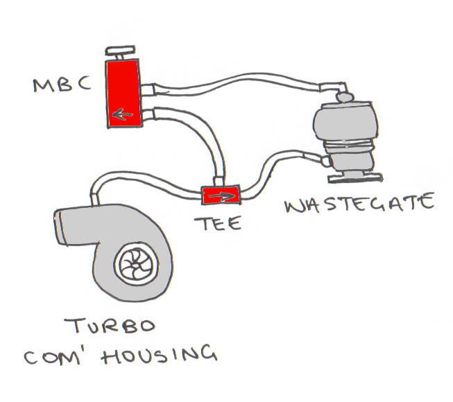
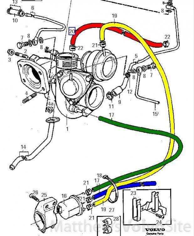
Below is a diagram of the basic turbocharger setup. You'll see the blue manual boost controller depicted inline with the vacuum system. This is a simple and easy to read manual boost controller basics diagram that will show you what's going on. As the exhaust side of your turbo spins, it builds positive boost to your engine.
Complete Diagnosis & Tests Technical Manual with electrical wiring diagrams for John Deere Tractors 5045E, 5055E, 5065E & 5075E (North Amereca), with all the shop information to maintain, test, and service like professional mechanics.. John Deere Tractors 5045E, 5055E, 5065E & 5075E (FT4) workshop Diagnosis & Tests technical manual includes: * Numbered table of contents easy to use so.
Boost pressure can be bled off in a few ways, using a mechanical bleeder type system with a needle and a seat, a small opening or bleed hole, or the more reliable and accurate way using an electromechanical solenoid. Manual Boost Controllers Starting with one of the simplest forms of boost control, lets look at a Manual Boost Controller.
controller is adjusted to create a 2 psi differential then you will have 12 psi of boost. Since you can control the differential, you can add boost beyond what your stock actuator is capable of producing. Referring to figure 1 will show a diagram of the valve and the proper connections for installation.
Methanol Wideband Diagram; MicroTech Accessories; Mitsubishi Applications; MT/LT12 WIRING DIAGRAMS; MT/LT8 WIRING DIAGRAMS; MT2/4 WIRING DIAGRAMS; My account; My Account; Nissan Applications; Odometer Function; PB; PD; PD5; power hub 16; Power Hub 16; Power Shifter; Print Repair-Reconfigure Form; Pro Boost Controller Guide & Diagram; Purchasing.
GFB Electronic boost controller instruction manual Go Fast Bits P/L P.O. Box 1017 Riverwood NSW 2210 Australia Ph: +61 (0)2 9534 0099 Fax: +61 (0)2 9534 3999
NXS Motorsports Manual Boost Controller - Diagram B: Modifying the Controller: The NXS Motorsports Manual Boost Controller will support boost levels in excess of 25 psi. Should you find that you cannot reach your desired boost level, the boost controller may be modified by stretching the spring. This will allow the boost controller to support a.
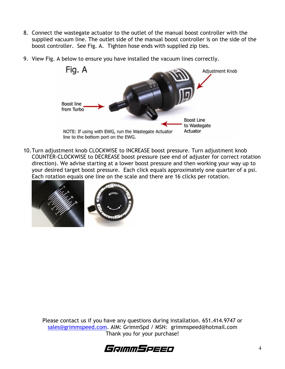
the boost controller) Adjusting the Boost Pressure - Adjustment to the boost controller is made by tuning the boost dial (see diagram below) - Turn in a clockwise direction to increase boost and anti-clockwise to decrease boost - Before making any adjustments install a boost gauge - Before any adjustments are made turn the boost controller dial.

Hypertune Universal Adjustable Manual Turbo Boost Controller Kit 1 30 Psi Dalam Kabin Meningkatkan Kontrol Ht3123
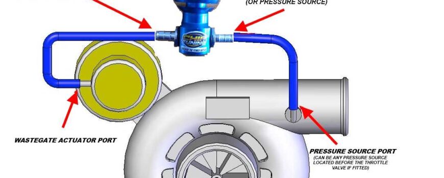
Allow the engine to cool down before installing your boost controller. Locate the pressure source port and the wastegate actuator port on the turbocharger assembly.; Remove the factory boost control solenoid if fitted from the boost pressure supply port while leaving the solenoid connected to the ECU.; Install your boost controller in the wastegate pressure line with the wastegate arrow.
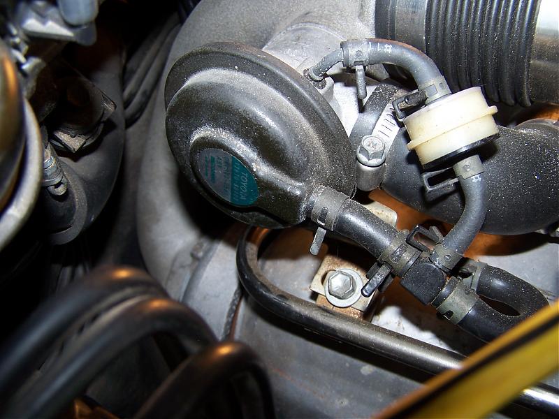
The boost controller interrupts the pressure line that runs into the wastegate actuator, allowing you to increase boost over stock levels. Step 1: Find your wastegate actuator which is usually attached to the turbo, unless you are using an external wastegate. The wastegate actuator will have a vacuum line port that runs to a boost source.
linearity between duty cycle and boost. They usually have reduced control authority compared to a dual port wastegate. Dual port wastegates are easier to tune because of reasonable linearity between control pressure and boost pressure, have better control authority than the single port style (especially if used with an external pressure
A Manual Boost Controller As you modify your RX-7 by opening the intake and exhaust, your boost will rise unless you reduce the restriction of the boost control vacuum line. By replacing the restrictor pills with needle valves you can control the boost level and amount of pre-spool the secondary turbo receives (which causes the boost spike at.
Manual Boost Controller. I bought the Grimmspeed manual boost controller. I really liked the features of adjustability on this manual boost controller overt the others I looked at. So far so good been holding pressure real nice. I am using it for my low boost Honda Build. Holds 10psi just fine no spikes.
P1197 Low voltage in the circuit of the oxygen controller installed after the catalyst P1211 Pressure controller reading above or below normalized parameters P1217 Code 1217 reports an intermittent signal from the pedal position sensor. It is necessary to check the integrity of the devices and their contact, as well as wiring.
Boost pressure adjuster 1 Hall-effect sensor, camshaft 1 Rail pressure control valve Throttle valve Volume control valve: F02: 20: M57, TU: Solenoid valve, exhaust gas recirculation Oil level sensor Electric changeover valve, swirl flaps Preheating control unit Electrical changeover valve, engine mount Heating, crankcase breather Boost pressure.
Voodoo Inline MBC. Voodoo Inline MBC - Universal Manual Boost Controller All Anodized Billet Aluminum Manual Boost Controller Add some Black Magic to your Turbo!... $24.95. Sale: $19.95. Save: 20% off.
www.pridemobility Q-Logic Controller Q-Logic Controller Features Figure 1 provides information on the Q-Logic components and connections. Use this diagram to familiarize yourself with the function and location of each component before using the Q-Logic Controller. The following functions are available with the Q-Logic Controller: Joystick.
Product Description: Electronic Boost Controller Product Number: TS-03011001 to TS 1013.. - Refer to the following table and diagram for detail on wiring the e-Boost2. Wire Connect to RED + 12 Volts switched through ignition – connect via 5 Amp fuse supplied
Install the boost control solenoid using new vacuum lines. Mount the boost solenoid away from any direct heat sources and route all vacuum lines away from heat or moving parts. If the factory setup includes a restrictive mechanical control or an electric solenoid, they will need to be bypassed for the boost controller to work as intended.
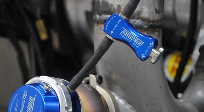
Turbosmart Manual Boost Controllers Tee Installation Tutorial How-To Installhttp://www.jegs /p/Turbosmart/Turbosmart-Manual-Boost-Controllers/3487224/1000...
Mechanical (Manual) Boost Controllers. A mechanical boost controller (also known as a manual boost controller) is a set-and-forget type of setup. You dial-in the exact amount of boost you want via manual knob, close the hood, and the controller will maintain that level regardless of throttle position, engine speed, or atmospheric conditions.
Mechanical (or manual) boost controllers offer up to two boost settings set by the driver and controlled via a switch. They are easy to fit, simple in operation and require little maintenance. Electronic boost controllers are a far more sophisticated solution offering a host of boost settings mapped against different triggers like gear change.
Mar 05, 2020 · The Holley EFI electronic boost controller uses one input & two outputs for the dual boost solenoid control type. The "Boost −" solenoid is the "Vent" solenoid, and the "Boost +" solenoid is the "Fill" solenoid. Both are Outputs. The solenoid +/− "Output Type" is selected in the Inputs/Outputs screen of the Boost ICF, then Pin-Mapped.












0 Response to "43 Manual Boost Controller Diagram"
Post a Comment