43 Ls1 Pcv System Diagram
I have a stock LS1 Carburated with the Edelbrock/ MSD Kit. My valley tray does not have a breather like other later LS motors. I need to set up a PCV system for it but not sure whats the best way to. I don't want pressure problems and start blowing seals or have the motor running like trash. I also have a catch can with an optional breather that can be plugged. 5,669 Posts. #5 · Sep 7, 2013. 65ChevyIINova said: I am putting an LS1 intake on my 5.3 and I am not sure if my plan for the PCV hose routing is 100% correct. My drivers side valve cover has the hole for the PCV hose. This originally just went to an opening on the top of the truck intake. There is also a port on the passenger side valve cover.
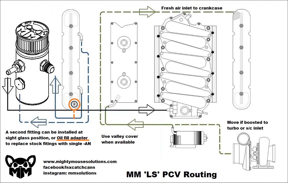
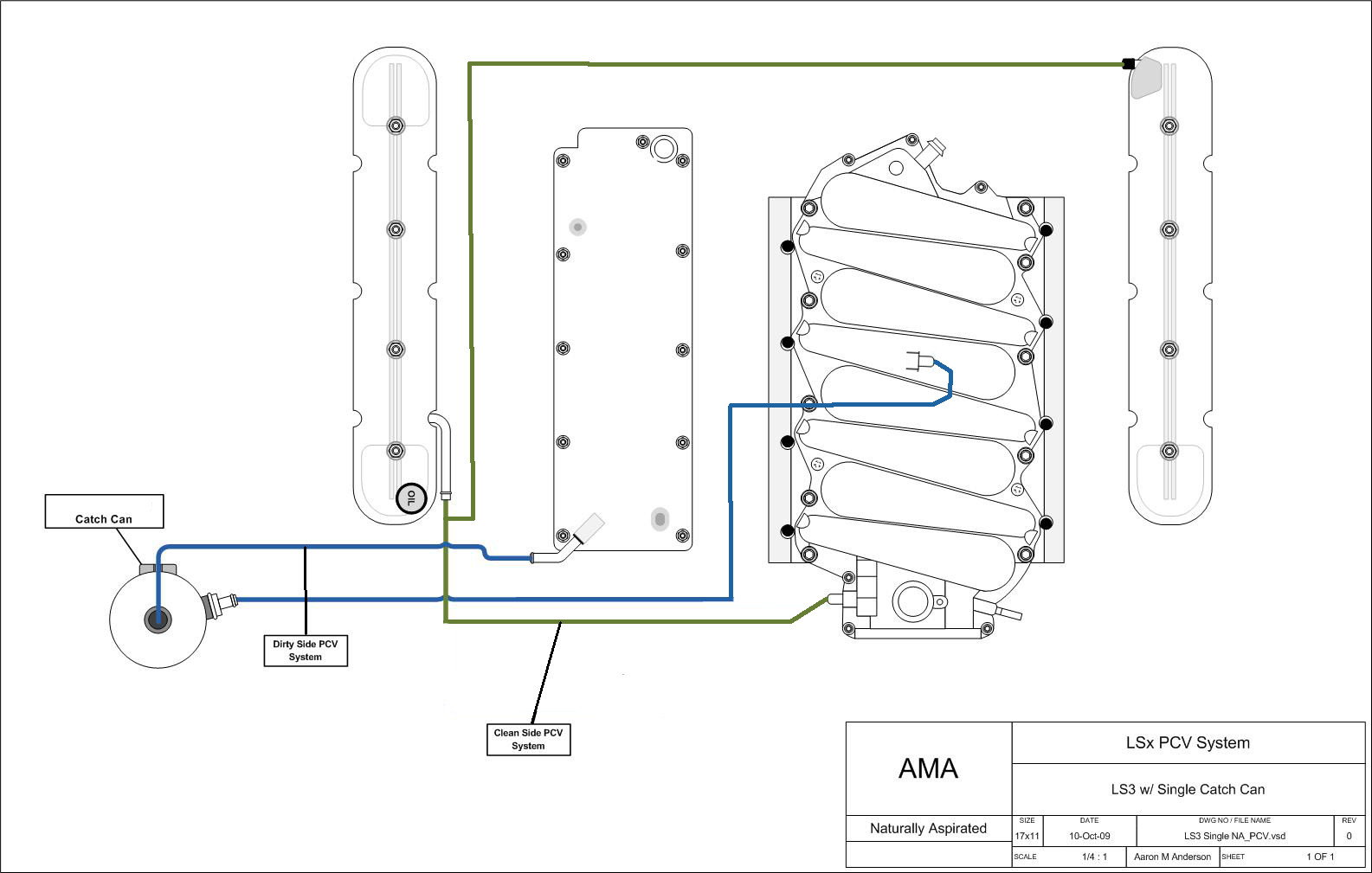
haust manifolds or similar LS Engine style Exhaust Manifolds. Positive Crankcase Ventilation System (PCV) How to set up your PCV system: There are two ports on the engine that make up the PCV system. The ports on the engine are: 1) Left rear (driver side) valve cover. 2) Top center of the inlet manifold.
Ls1 pcv system diagram
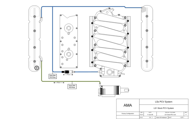
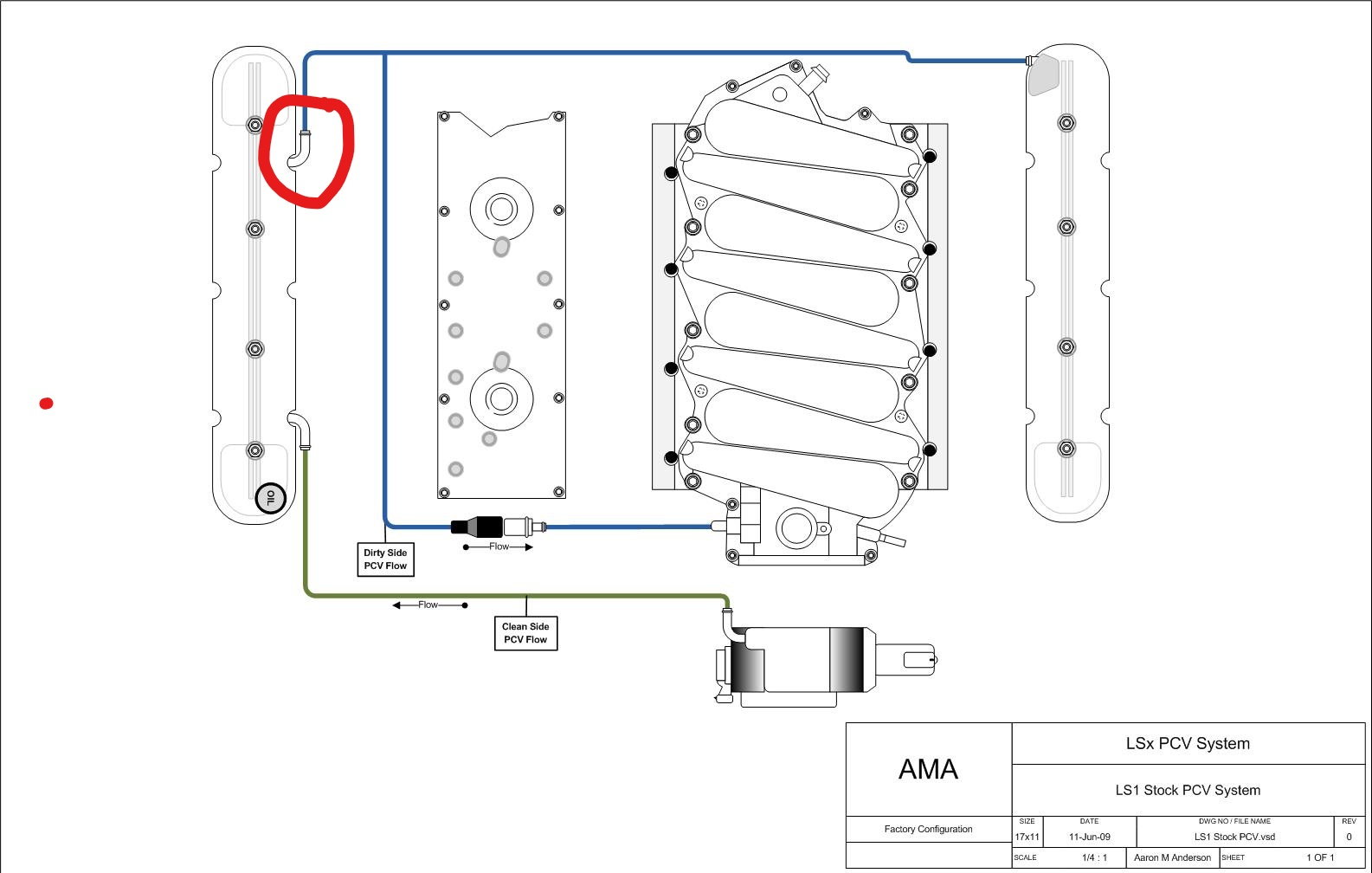
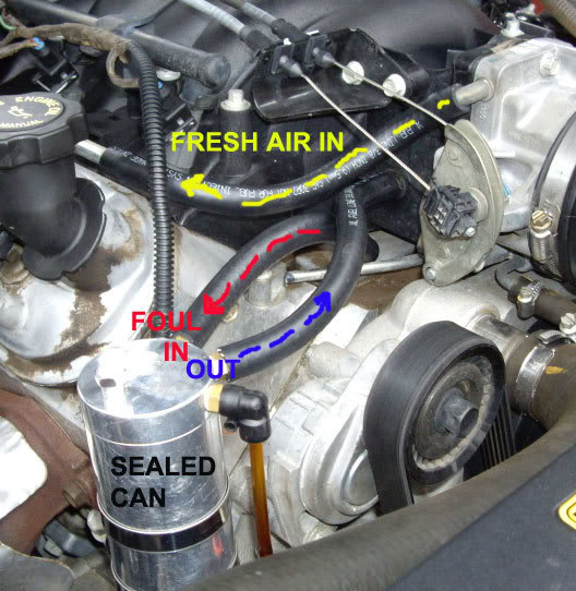
IMHO GM screwed the pooch (<us) by using this is a POS PCV system and on top of it, over charging us ($85-$140 depending on where you get it) for when you need to replace it. The PCV setup runs from the rear of the driver’s side valve cover behind the intake where it splits, one tube goes to the passenger valve cover the other comes along the. Here is another diagram showing the normal operation of the crank case ventilation system with half of the system greyed out: That pathway is used around 90% of the time you drive the car. A little blow-by is pushed into the crank case but the intake manifold sucks it up and the oil separator in the valve cover keeps most of the oil from. COMPLETE REDO of PCV System(pics writeup) This is a discussion on COMPLETE REDO of PCV System(pics writeup) within the General Help forums, part of the LSx Technical Help Section category; Finally ripped out ALL of the pcv lines on my 98. If you guys dont already know the 98s have.
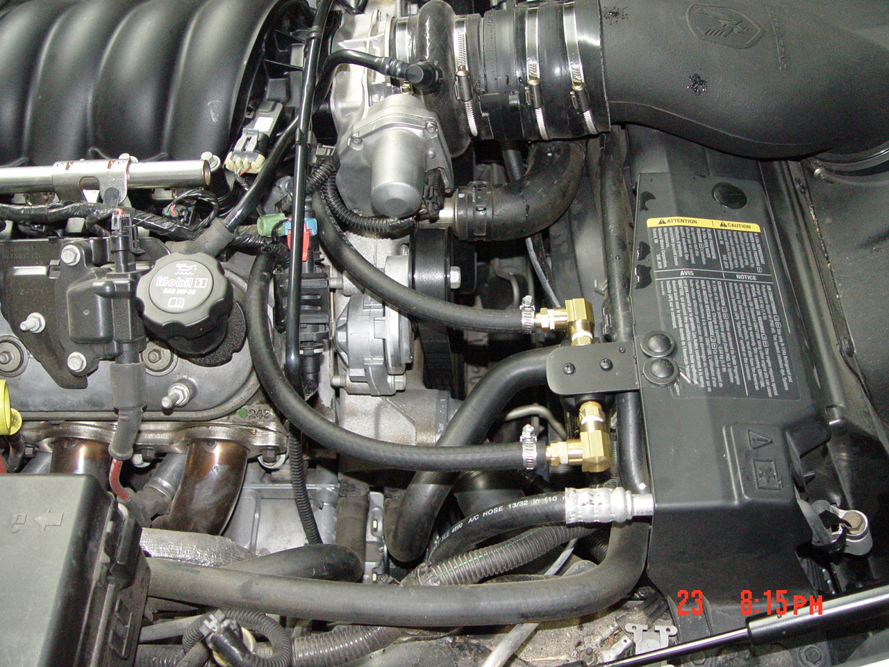
Ls1 pcv system diagram. 11,821 Posts. #6 · May 18, 2014. On the LS3 with an automatic trans, the driver side rear vent goes to the intake on the passenger side, just under the MAP sensor. The passenger side front vent goes to the intake tube, between the throttle body and MAF sensor. If it's a manual trans LS3, the PCV is in the lifter valley, not the driver valve cover. Thunder Racing LS1 to LS6 PCV Conversion Kit : $169.99. This pic shows the difference in the to PCV systems. Bottom is the LS6 PCV system and the top is the factory LS1 PCV system. You can also see from this pic why some trimming is required. Start of by removing the old LS1 PCV system, I forgot to take pics of this stage, just thought it was. what i run im my ls1 5.7l vx ss COMPLETE REDO of PCV System(pics writeup) This is a discussion on COMPLETE REDO of PCV System(pics writeup) within the General Help forums, part of the LSx Technical Help Section category; Finally ripped out ALL of the pcv lines on my 98. If you guys dont already know the 98s have.
TITLE E-ROD Crate Engine Control System REV 31MR11 PART NO. 19257246 PAGE OF DATE REVISION AUTH 3 PERFORMANCE PARTS GM 30 Positive Crankcase Ventilation System (PCV) How to set up your PVC system:-Front O2s Rear O2s Rear DR Side Foul Air Connection Fresh Air / Filtered Air Connection Vacuum Source Rear Driver ˇs Side Foul Air Example Here is another diagram showing the normal operation of the crank case ventilation system with half of the system greyed out: That pathway is used around 90% of the time you drive the car. A little blow-by is pushed into the crank case but the intake manifold sucks it up and the oil separator in the valve cover keeps most of the oil from. The primary component in the positive crankcase ventilation (PCV) system is the PCV flow metering device (or orifice). Vacuum changes within the intake manifold result in flow variations of the blow-by vapors. If abnormal operating conditions occur, the design of the PCV system permits excessive amounts of blow-by vapors to back flow through. Needing Diagrams! This is a discussion on Needing Diagrams! within the Firebird / WS6 forums, part of the Vehicle Specific category; I need a vacuum line diagram.. and a coolant line one if possible. I wont to check over all my.
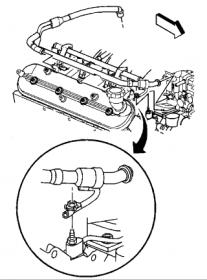
But the PCV valve has this hose that makes a 180 and goes towards the back of the intake about 3 inches. But like i said.. mine is a 94. But I don't recall any T-type fittings on my 95 motor. Just a straight hose that goes from the intake fitting to the PCV valve. Plus it looks like the hose is 3/8's or 5/16's rubber fuel line, and i can tell. Just looked it up in the service manual, and frankly cannot find a difference. Diagrams look the same. We will need someone with an 04 to check in to know for sure. The LS2 is definitely different. There is no PCV valve in the line from the valley to the throttle body, and the fresh air line comes off of the air intake, not the throttle body. haust manifolds or similar LS Engine style Exhaust Manifolds. Positive Crankcase Ventilation System (PCV) How to set up your PCV system: There are two ports on the engine that make up the PCV system. The ports on the engine are: 1) Left rear (driver side) valve cover. 2) Top center of the inlet manifold. Just blank off the rear right PCV tube on the LS1 valve cover. Use another #12579145 if you like. 03-26-2010, 07:16 AM #8. HSV-GTS-300. View Profile View Forum Posts View Blog Entries View Articles Marsupial Join Date Apr 2004 Location Perth Australia Posts 16,212 vCash 500.
After many complaints, GM finally issed a service bulletin to address this issue on all of the GEN 3 engines. They have replaced the ball-type PCV valve with a new fixed orifice design that is used in the GM trucks. This design will help reduce oil-consumption on your LS1. This product was added to our catalog on Thursday 23 February, 2006.
Variety of ls1 pcv system diagram electrical wiring layout. A wires layout is a sleek basic photo symbol of an electric circuit. It reveals the elements of the circuit as streamlined types, as well as also the electrical power as well as indicator links in between the devices.
Re: LS1 hose diagram. « Reply #6 on: November 07, 2012, 12:57:00 PM ». Having a LS6 intake dont matter for PCV if you dont have LS6 valley cover, and LS1/LS6 valve covers. Pic 2: the top steel elbow is your fresh air to the valve cover (the connection in Pic 3). Bottom nipple can be capped or hooked up to PCV valve, if capped you can use the.
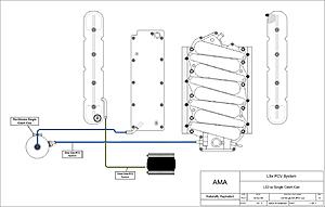
Single Oil/Air Seperator PCV Routing LS1 Valley Pan, External PCV Valve - Turbo Plug From Intercooler One Way Check Valve Orišce or PCV Valve Orišce or PCV Valve Driver side Valve cover Intake Manifold Throttle Body Clean Side Dirty Side Passenger side Valve Cover el an e or Single Oil/Air Seperator PCV Routing LS6, LS2, LS3 Valley Tray.
This is a simple PCV delete for those who want to stop messy oil from entering their intake but dont want to spend the money on a catch can. This may really help those with vararam and nitro plate so they dont have to drill holes in their maf sensors, etc.
IMHO GM screwed the pooch (<us) by using this is a POS PCV system and on top of it, over charging us ($85-$140 depending on where you get it) for when you need to replace it. The PCV setup runs from the rear of the driver’s side valve cover behind the intake where it splits, one tube goes to the passenger valve cover the other comes along the.
Agree, no PVC catch can is breathing from the atmosphere. Plus as stated the system is supposed to suck the air from the valve covers from the crank case and is now sucking air from the atmosphere (path of least resistance).
Tech: Crankcase Pressure Control - Oil and Air Control. By Don Creason January 10, 2013. Proper control of engine crankcase pressure and oiling can be a significant advantage in terms of horsepower and engine life. While all modern factory engines are equipped with a PCV system, those factory parts seldom do enough.
How to set up your PVC system: • There are three ports on the LSX long block that make up the PCV system. There are two foul side ports. Both of these ports should be connected to the intake manifold and be exposed to vacuum at idle. • The two ports are 1) Front port on the valley cover. 2) Left rear (driver) valve cover.
The LS1 PCV system is far from perfect, and GM moved one step closer to a better system by changing it around when the LS6 came out. The LS6 setup pulls crankcase pressure out from the more sheilded valley cover area, rather than a valve cover. While the results aren't spectacular, generally less oil will be sucked in over the same engine with.
RX Catch Can installation& PCV system The LS based motors have a PCV system that at best is pretty ineffective. This allows oil mist to enter the intake manifold causing undue carbon buildup on the piston tops & valve surfaces & detonation from the contaminated air charge. The catch can goes
A PCV system is designed to force any positive crankcase pressure into the intake manifold, rather than continue allowing the engine to build up pressure inside. The LS1 system just happens to force oil along with the air as well, so GM seemed to take a stab at fixing the issue with the LS6 system.
Some LS motors get a lot of oil accumulating in the intake manifold. One of the first things you can do is install an baffled oil catch can. GM also tweake...
the PCV valve and into the intake manifold where they are burned. It is especially important for cars that are driven occasionally to have a properly functioning PCV system. With occasional use and or short trips a good PCV system will help rid an engine of moisture accumulated in the crankcase. Typical PCV system configuration, PCV valve










0 Response to "43 Ls1 Pcv System Diagram"
Post a Comment