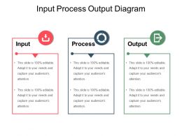
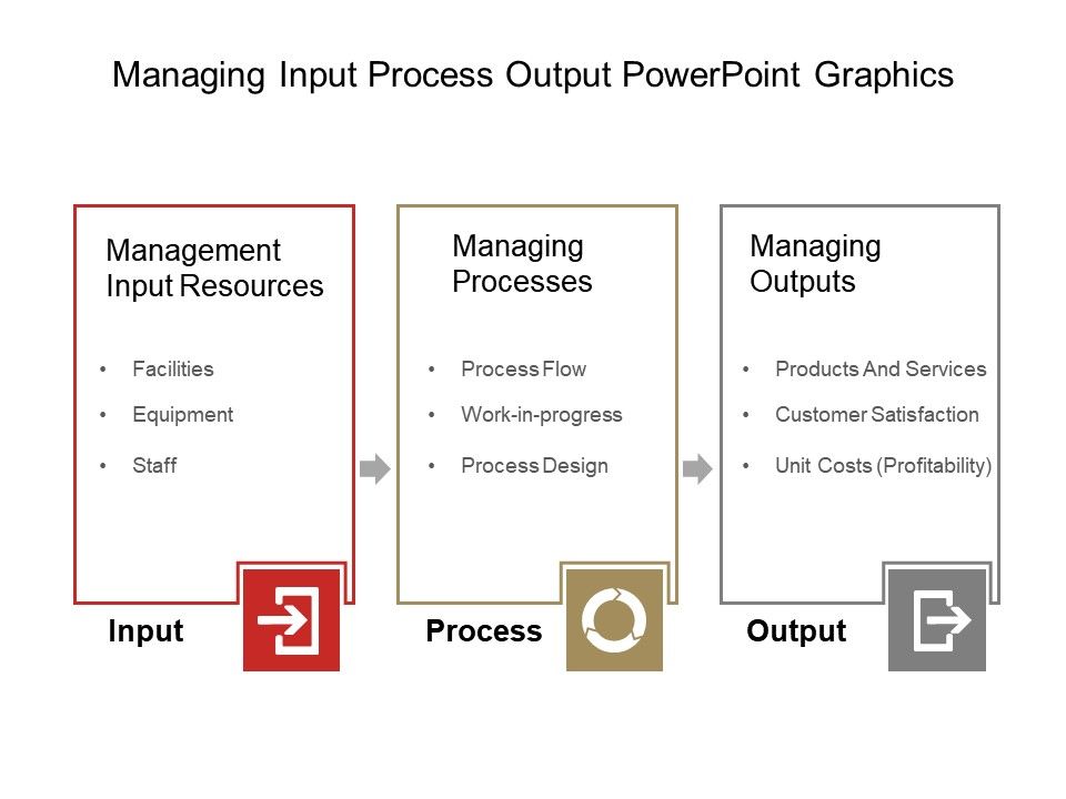
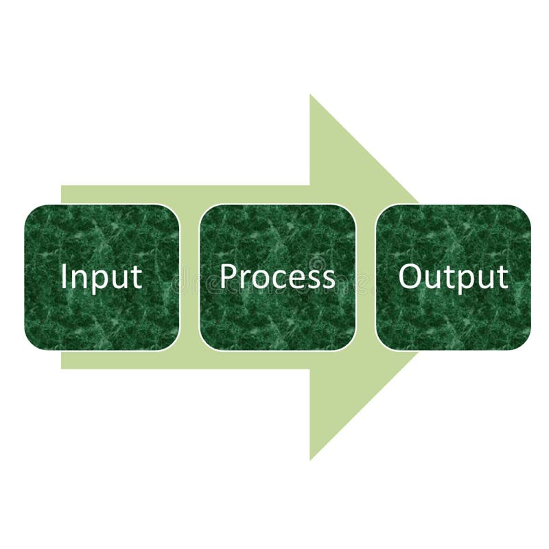
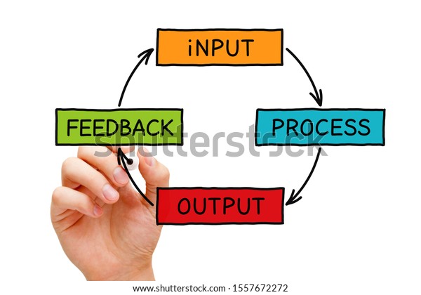
43 Input Process Output Diagram
We can put together the following input-output diagram for this process: Exercise: Benzene Production Input-output Diagram. Consider a process where toluene is fed into a process at 1000 kg/hr and hydrogen is fed at 82 kg/hr. The following reaction takes place in the process: C7H 8 +H 2 C6H 6 +CH 4 C 7 H 8 + H 2 C 6 H 6 + C H 4. Start studying 4.1.1 Input, Process, Output diagram. Learn vocabulary, terms, and more with flashcards, games, and other study tools.
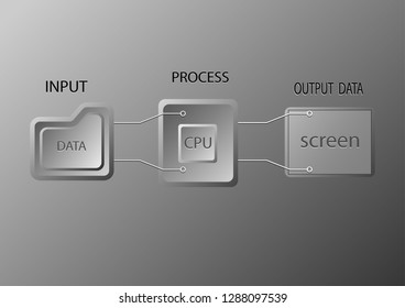
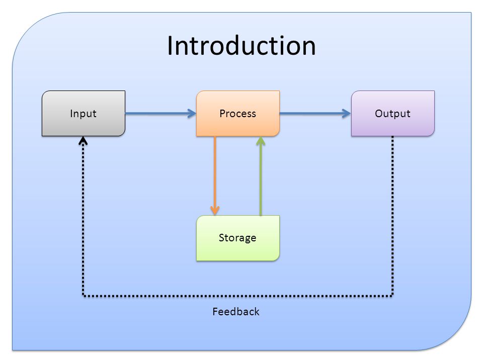
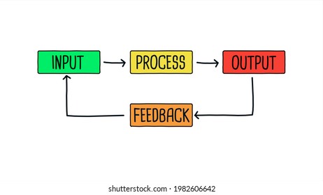
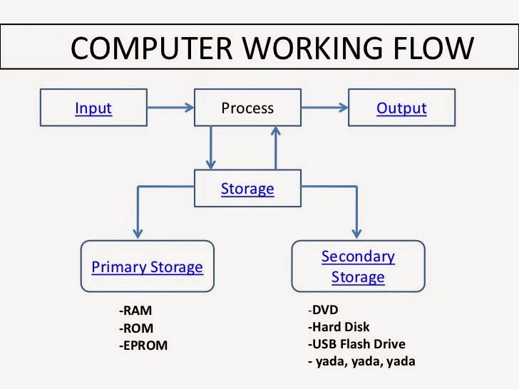
The Input-Output (IPO) Model is a functional graph that identifies the inputs, outputs, and required processing tasks required to transform inputs into outputs.The model is sometimes configured to include any storage that might happen in the process as well. The inputs represent the flow of data and materials into the process from the outside.

Input process output diagram
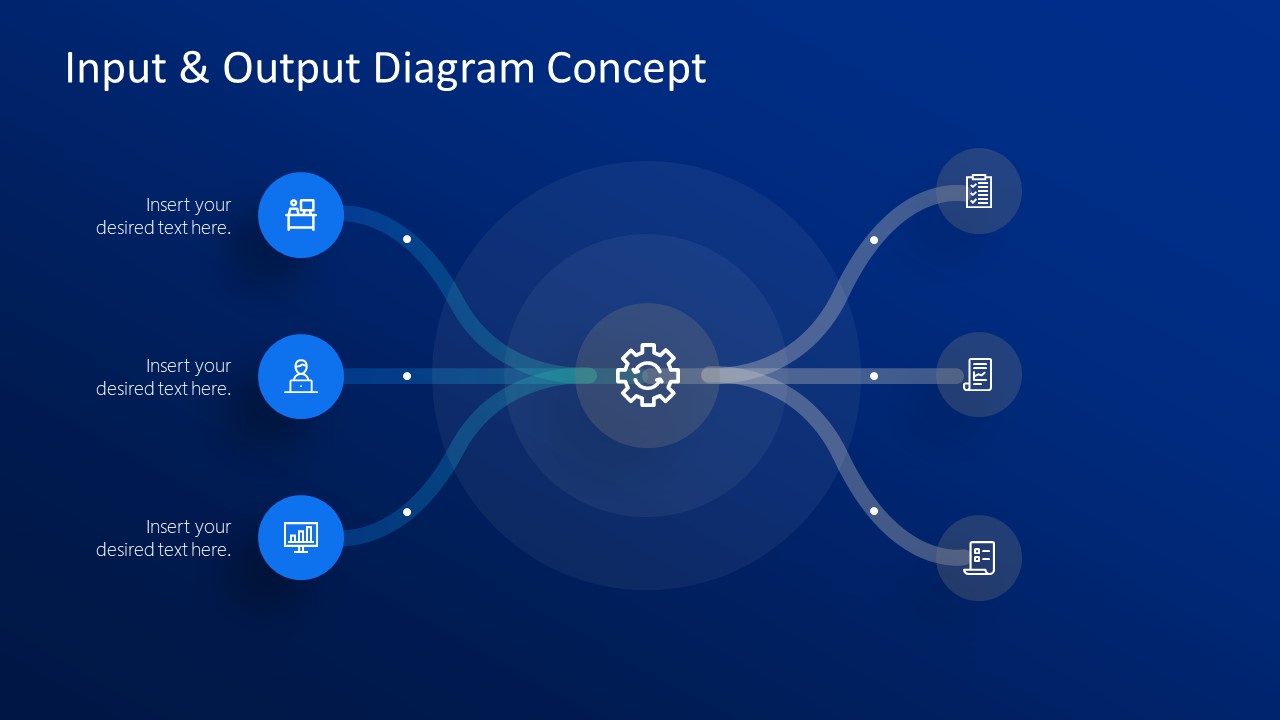
This PowerPoint diagram template input & output concept can illustrate several model presentations. Such as, IT project processes, message signals, data streams, pipelines, and more. It can also benefit in presenting central management system of command center and control room data. Item # FF0237-01. Input Process Output. Input‚ Process and Output In any business‚ the first thing you have to think about is the input.The input varies depending on what kind of a business you are thinking of. Ill be discussing the inputs‚ Processes and outputs with regards to farming. There are different types of farming such as arable farms‚ which the main way of making profit is by growing crops. Input Process Output Diagram. Stages ? 'Stages' here means the number of divisions or graphic elements in the slide. For example, if you want a 4 piece puzzle slide, you can search for the word 'puzzles' and then select 4 'Stages' here.
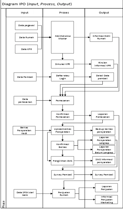
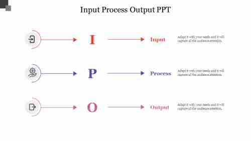
Input process output diagram. Input - Process - Output. Use Creately's easy online diagram editor to edit this diagram, collaborate with others and export results to multiple image formats. You can edit this template and create your own diagram. Creately diagrams can be exported and added to Word, PPT (powerpoint), Excel, Visio or any other document. Input Process Output Diagram. Stages ? 'Stages' here means the number of divisions or graphic elements in the slide. For example, if you want a 4 piece puzzle slide, you can search for the word 'puzzles' and then select 4 'Stages' here. The HIPO (Hierarchy plus Input-Process-Output) technique is a tool for planning and/or documenting a computer program. A HIPO model consists of a hierarchy chart that graphically represents the program's control structure and a set of IPO (Input-Process-Output) charts that describe the inputs to, the outputs from, and the functions (or. IPO Diagram is often used for the analysis of six sigma. In a simple diagram of an IPO can be shown in the picture beside. This diagram to easily illustrate the relationship of input, process and output. This graph provides a clear explanation of the inputs used and outputs must be generated by each function.
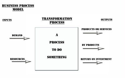
Y is the dependent output variable of a process. It is used to monitor a process to see if it is out of control, or if symptoms are developing within a process. It is a function of the x's that contribute to the process. Simple method for identifying and mapping inputs and outputs of a process. Production process input-transformation-output diagram INPUTS TRANSFORMATION OUTPUTS Feedback Loop Conversion process (grinding to fine coffee) Raw materials (coffee), labor, capital, management Goods and Services. OPERATIONS MANAGEMENT AT STARBUCKS COFFEE 4 Figure a. Input-transformation-output diagram of Starbucks. The input and output is useful for demonstrating a range of process diagrams. Make use of our input output templates, showcase the business model, business process, or any process flow. The input process highlights the resources used in completing a task, whereas the output is the outcome derived from these resources. Input-Process-Output Model Dave Braunschweig. Overview. The input-process-output (IPO) model is a widely used approach in systems analysis and software engineering for describing the structure of an information processing program or another process.Many introductory programming and systems analysis texts introduce this as the most basic structure for describing a process.
Input-process-output (I-P-O) is a structured methodology for capturing and visualising all of the inputs, outputs, and process steps that are required to transform inputs into outputs. It is often referred to, interchangeably, as an I-P-O model or an I-P-O diagram, both of which make reference to the intended visual nature of the method. The input-output diagram is a handy analysis tool that looks at the inputs and outputs to any transforming process. It can be used in this simple overview form or can be extended to include more details and these are typically called control diagrams or Process models. Data Flow Diagrams show information transfers and process steps of a system. The general concept is an approach of a depicting how occurs input in a system, further processes and what runs out. The aim of DFD is in accomplishing of understanding between developers and users. Data flow diagrams are maintained with other methods of structured systems analysis. Input Processing Output Diagram Of. IPO (Input Process Output) is a commonly used model in software engineering, which is based on the 3 major components - input, output, and process. It also plays a crucial role in system analysis and describes how information is processed through different phases. Once data is collected through an input mechanism, various steps like.
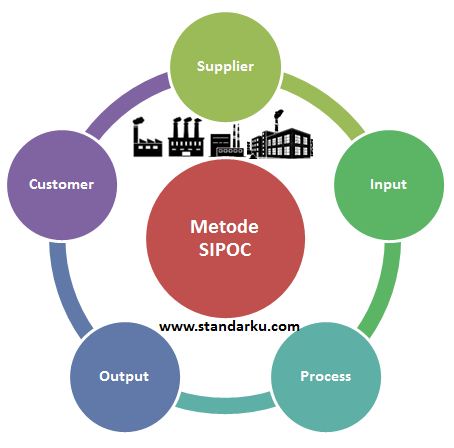
Skill level: Basic Description. The suppliers, inputs, process, outputs, customers (SIPOC) diagram defines the scope of work for a team and identifies at a high level the potential gaps (deficiencies) between what a process expects from its suppliers and what customers expect from the process.
The input-process-output model has historically been the dominant approach to understanding and explaining team performance and continues to exert a strong influence on group research today. The framework is based on classic systems theory, which states that the general structure of a system is as important in determining how effectively it.
Suppliers, Inputs, Process, Output, Customers (SIPOC Diagram) A SIPOC is a high level process map that includes Suppliers, Inputs, Process, Output, and Customers. The video below explains SIPOC and shows several examples from real world Six Sigma projects. You can order SIPOC template with the Lean Six Sigma templates bundle.
The input-process-output (IPO) model, or input-process-output pattern, is a widely used approach in systems analysis and software engineering for describing the structure of an information processing program or other process. Many introductory programming and systems analysis texts introduce this as the most basic structure for describing a process.
The level of output, Q, depends upon the use of the two inputs, L and K. Since output Q is the same at all points on an isoquant, ∆Q is zero for any change in L and K along an isoquant. Suppose that, at a point on the isoquant, the marginal product of capital (MPk) is 3 and the marginal product of labour (MP L) is 6.
Input Process Output. Input‚ Process and Output In any business‚ the first thing you have to think about is the input.The input varies depending on what kind of a business you are thinking of. Ill be discussing the inputs‚ Processes and outputs with regards to farming. There are different types of farming such as arable farms‚ which the main way of making profit is by growing crops.
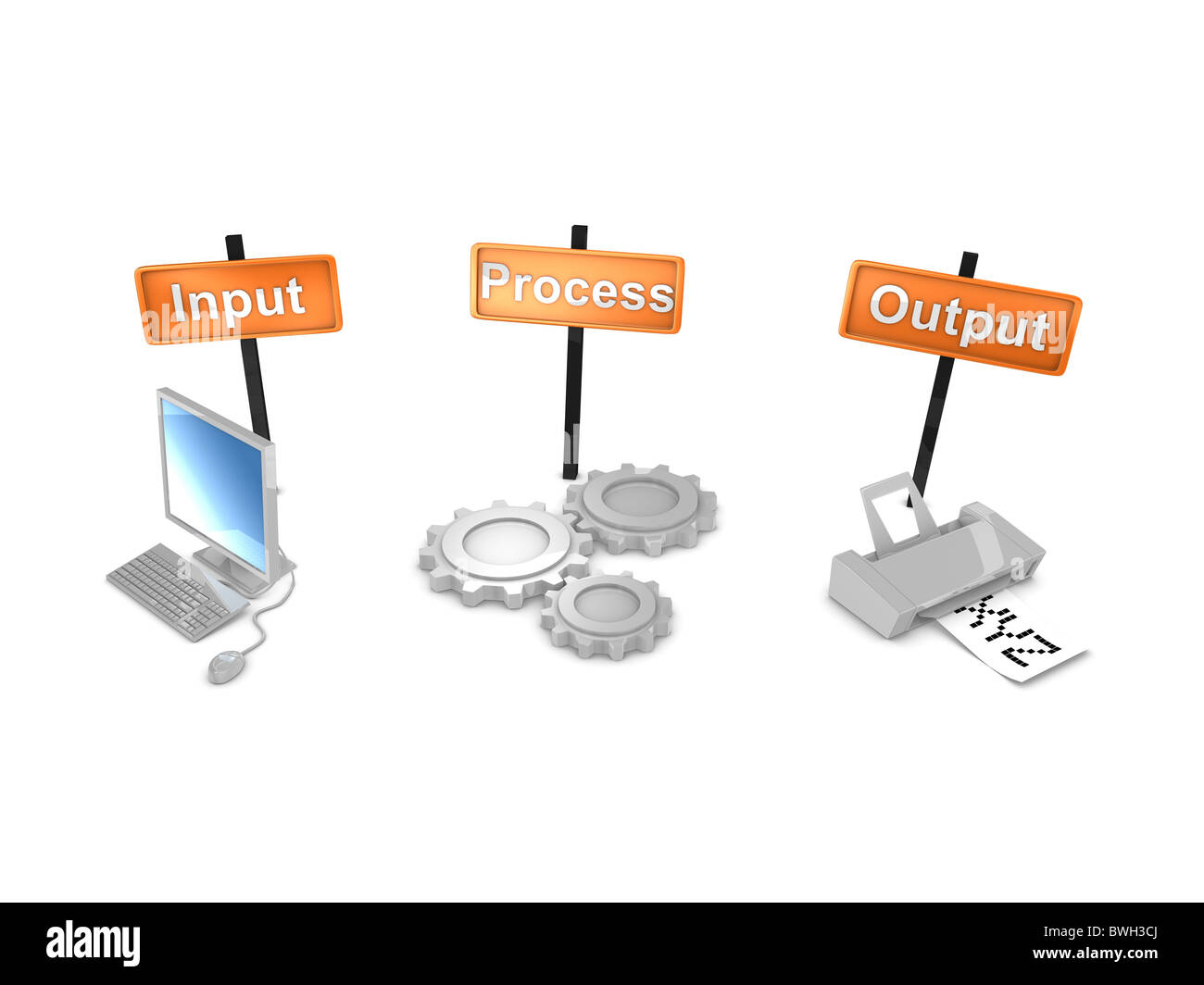
Input - Data which is required in order to create the required outputs. Process - The steps involved in creating the outputs from the inputs. An Input Process Output table then is a table listing what inputs are required to create a set of desired outputs and the processing required to make that transformation occur.
Explore input, process, output, and storage, or IPOS, how the system works, and the four functions that make up an information system. Updated: 08/22/2021 Create an account
A HEAT ENGINE PROCESS IS CHARACTERIZED BY ITS EFFICIENCY, η η= net work produced heat input = Wnet Qin However, WNET = QNET = QIN – QOUT and substituting into above η= Qin −Qout Qin =1− Qout Qin 0 < η < 1 If only the 1st law controlled, η could equal 1. However, by the 2nd law, since Q OUT > 1, then η < 1.
The UML diagram is a powerful tool which lets visually represent all system's components, the interactions between them and relationships with external user interface. The Rapid UML solution for ConceptDraw DIAGRAM software offers diversity of UML flowchart symbols for drawing all types of UML diagrams. Uml Input Output Diagram
Input-output diagrams are the first step in designing a chemical process. An input-output diagram is the simplest form of flow diagrams used in industry. Input-output diagrams consist of one block with the inputs coming in one end and the outputs going out the other.
What is input process output diagram? A graphical representation of all the factors that make up a process. An input-process-output diagram includes all of the materials and information required for the process, details of the process itself, and descriptions of all products and by-products resulting from the process. Read remaining answer here.
Input Process Output. Stages ? 'Stages' here means the number of divisions or graphic elements in the slide. For example, if you want a 4 piece puzzle slide, you can search for the word 'puzzles' and then select 4 'Stages' here. We have categorized all our content according to the number of 'Stages' to make it easier for you to.
Once the Input Map is completed and the X's or Inputs in the Process have been identified, then you can move to the next step. The next step in the Six Sigma Root Cause Analysis is the C&E Matrix where we will Prioritize the Inputs by their Effect The change in the average value of the output caused by a ch... on the Outputs. Below is an Example of a Input (or Variables) Map with the first.
This PowerPoint diagram template input & output concept can illustrate several model presentations. Such as, IT project processes, message signals, data streams, pipelines, and more. It can also benefit in presenting central management system of command center and control room data. Item # FF0237-01.
Hierarchical Input Process Output ( Block Diagram) Use Creately's easy online diagram editor to edit this diagram, collaborate with others and export results to multiple image formats. We were unable to load the diagram. You can edit this template on Creately's Visual Workspace to get started quickly. Adapt it to suit your needs by changing.
Output: the outputs from the System of Interest. Customer: the external entities that receive the system outputs. The lower half of the Input-Output Diagram contains a high-level system Sequence Diagram [1]. This diagram shows how the basic functionality has to co-operate in order to transform the system inputs into the system outputs.
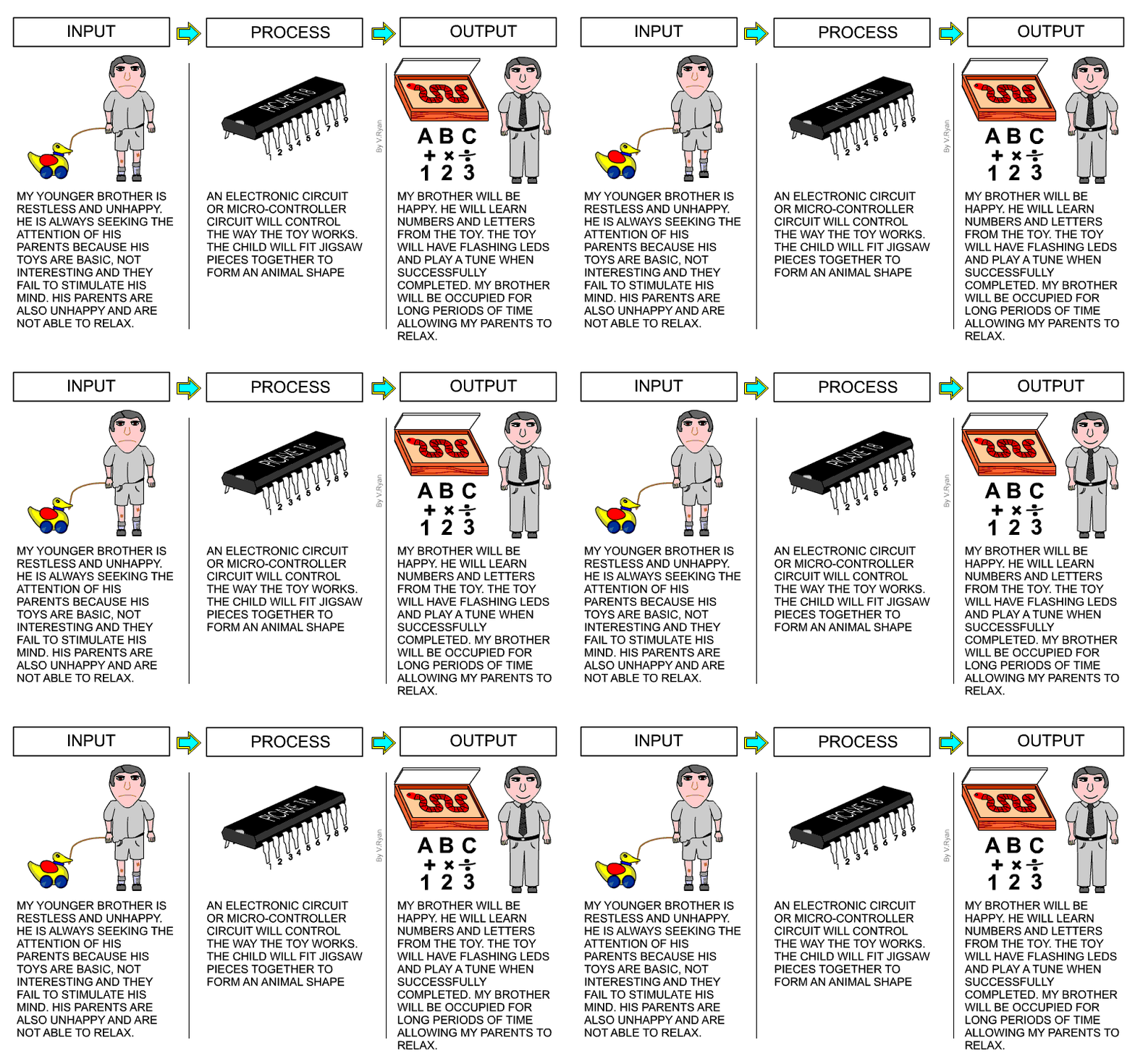
Input, process and output When considering electronic systems we can say that it is made up of 3 main parts. Input Process Output Definitions Data has to flow into. - A free PowerPoint PPT presentation (displayed as a Flash slide show) on PowerShow - id: 510715-ZDFkN
The Multi Input & Output Diagram concept for PowerPoint could be constructed for many reasons. For example. Input & output controls, input-process-output device (IOD), input/output device or IOM model for analysis. The diagram template will give a high-level representation of how system works. The inputs represent raw material or data that goes.














0 Response to "43 Input Process Output Diagram"
Post a Comment