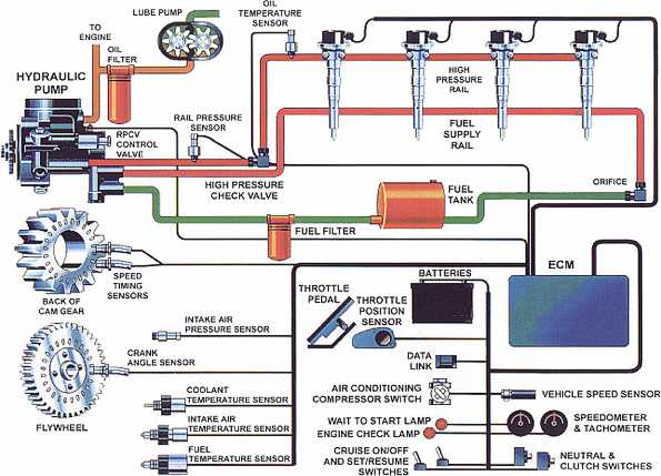
43 Cummins Isc Fuel System Diagram
Cummins ISC, ISL CM Engine Service Repair Manual CD ROM [] · Cummins ISC Cummins ISC CM Engine Wiring Diagram Schematic CD- ROM. For a schematic of the cab side wiring for the Cum- mins ISB and ISC electronic engines, see Fig. 1 for a standard vehicle wiring diagram.Jun 12, · Cummins ISC Hp Warm engine rough Idle. Access to Documents and Materials for Your Cummins Products Cummins produces a wide variety of documents to help customers get the most from their engines, generators and components. Much of this library is available online. Check out the digital resources listed below or contact us for help with your specific needs.
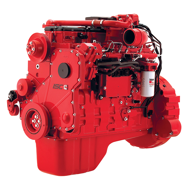
Cummins ISC Fuel Transfer Pump The Cummins ISC Diesel Engine is the electronic version of the C mechanical model. The ISC uses a electronically controlled fuel transfer pump compared to the older mechanical version. There have been some failures in our fleet with the electronically controlled pump but not in epidemic proportions.
Cummins isc fuel system diagram
23. Fuel Injector Connector. 24. Drain Tube. 25. Intake Manifold Air Heater / Elements. [thanks to Fritz] This entry was posted in Fuel Systems and tagged diagram, Dodge 24V Cummins (98.5-02), fuel. Bookmark the permalink. Show/Hide Details. We offer a great choice of Cummins C Series fuel system components, including fuel injectors, lift pumps, fuel lines, and fuel filters. We carry parts for 6CTA, ISC, and QSC 8.3 liter diesel engines. If you need any help finding a part, please use our quote request form or call us at 855.470.3525: our experienced sales staff. 5. Fuel rail 6. Fuel drain manifold 7. Fuel filter 8. Crankcase breather draft tube 9. Crankcase breather oil drain tube 10. Starter 11. Engine oil drain plug 12. Fuel lift pump (behind ECM) 13. Electronic control module (ECM) 14. Air compressor 15. Engine data plate 16. High-pressure fuel pump Engine Diagrams Page 3 of 21
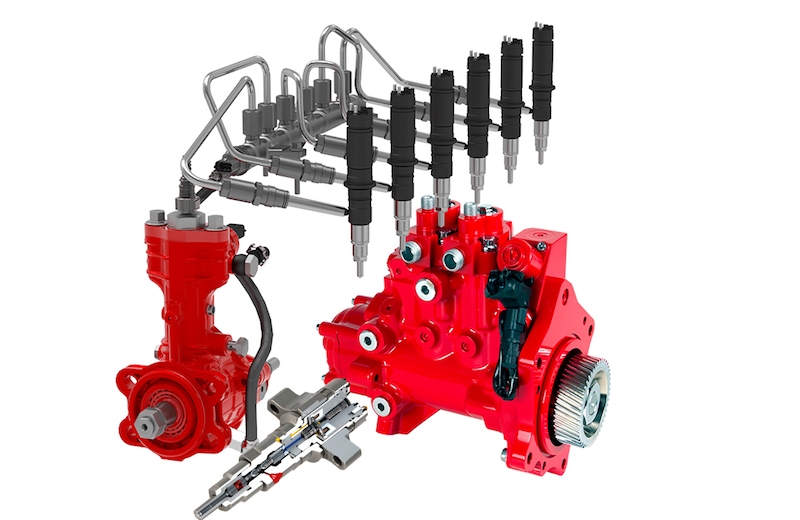
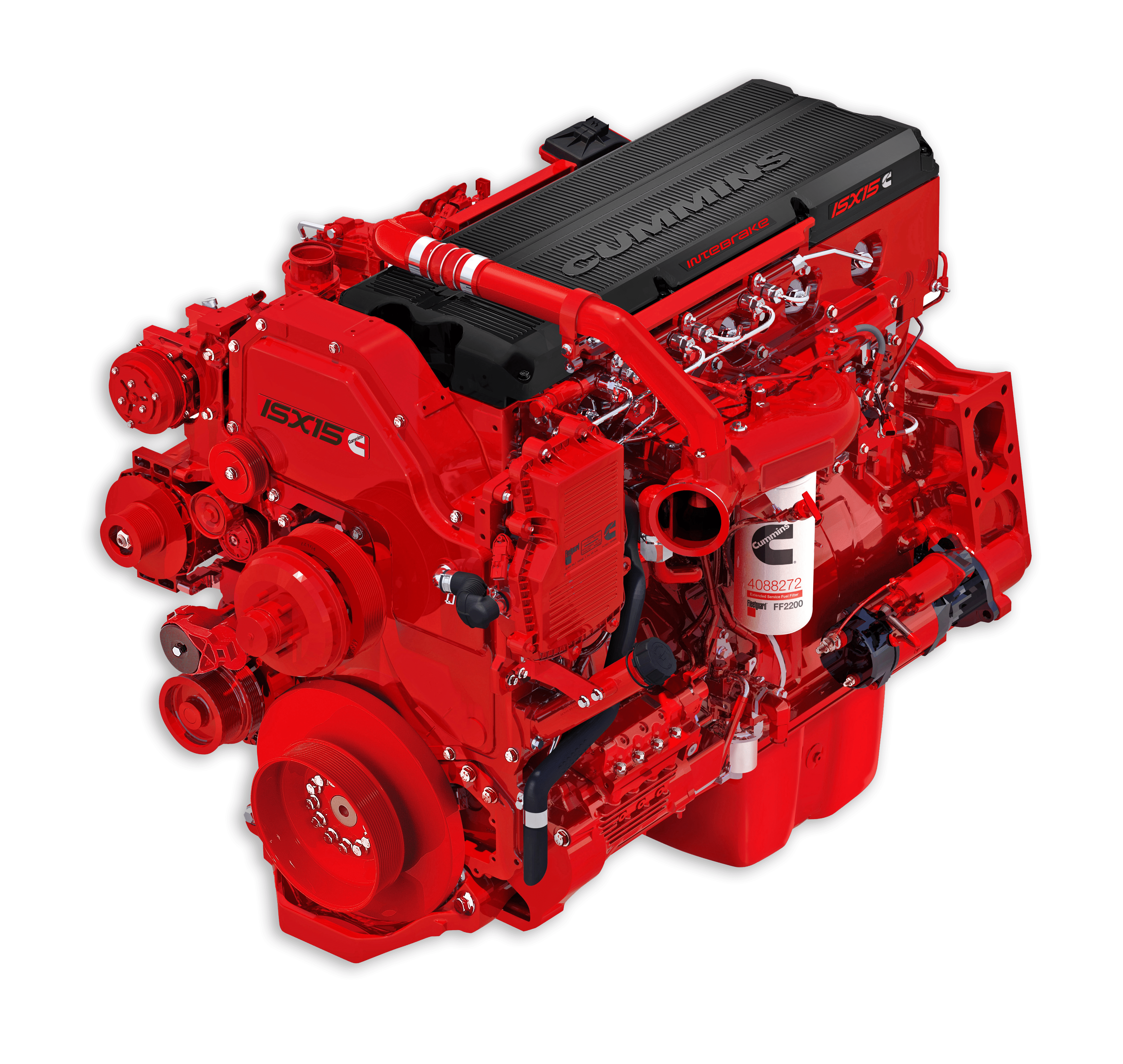
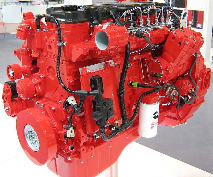
Cummins isc fuel system diagram. Cummins Isx Fuel System Diagram. Hello, 06 ISX has a noise and vibration under a hard pull with some smoke. At idle ( rpm) the line is half air and half fuel - foamy mix. M11 Engine Diagram_exhaust side. M11 Engine Diagram_fuel pump side. Fuel System Flow Diagram. Heavy Duty XPI Fuel System. The Cummins HD XPI System is a common rail system that provides the highest injection pressure of any other common rail system. Primarily targeted for mid-range and heavy-duty applications, the XPI system is the result of Cummins market leading technology. Beginning in 1998, Cummins introduced the ISC based off the earlier mechanical 8.3 C-series engine. The original ISC engine featured a Cummins Accumulator Pump System (CAPS). This CAPS pump was a computer controlled injection pump, with individual fuel lines to each injector. In 2003 the HPCR system was introduced. 5. Fuel rail 6. Fuel drain manifold 7. Fuel filter 8. Crankcase breather draft tube 9. Crankcase breather oil drain tube 10. Starter 11. Engine oil drain plug 12. Fuel lift pump (behind ECM) 13. Electronic control module (ECM) 14. Air compressor 15. Engine data plate 16. High-pressure fuel pump Engine Diagrams Page 3 of 21
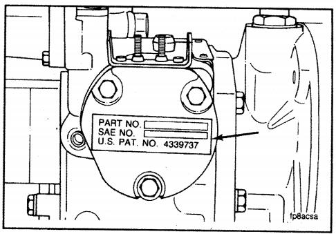
The original ISC engine featured a Cummins Accumulator Pump System (CAPS). This CAPS pump was a computer controlled injection pump, with individual fuel lines to each injector. In 2003, Cummins released the updated ISC engine. Among other differences, the most significant was the change to the High Pressure Common Rail (HPCR) fuel system. The fuel ignites from contact with the air that , due to compression, has been heated to an excessively high temperature. When the injector is energized an electromagnet moves a plunger that open the valve, allowing the pressurized fuel to squirt out through a tiny nozzle. The nozzle is designed to atomize the fuel to The Cummins manual that came with my 8.3 ISC states very clearly "do not pre-fill the fuel filters when changing". When I change my filters, I do as the manual says "turn the key to the "on" position and this will engage the fuel pump which will run for about 30 seconds. Cummins ISC & ISL Service Manual (CM2150) Factory printed manual. Factory Cummins engine service manual. Covers mechanical troubleshooting & repair. No coverage for engine electronic control system. Unloader & valve assy. Manufacturer reserves the right to make changes without prior notice.
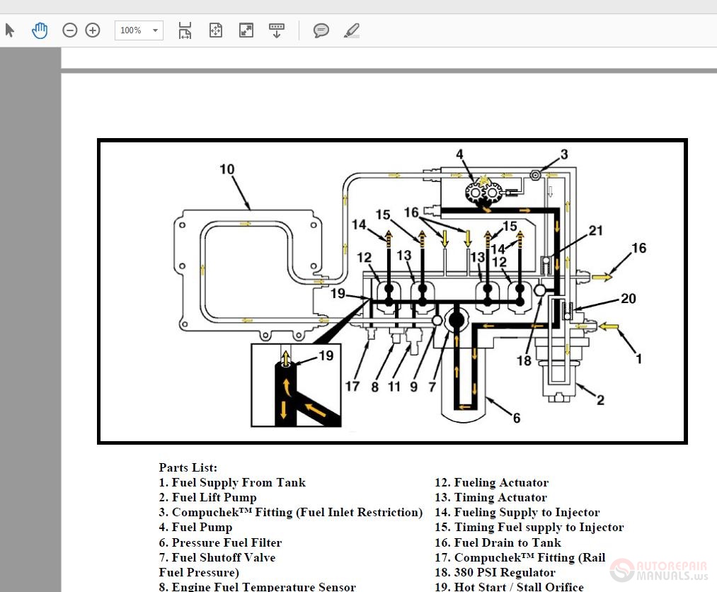
Cummins Accumulator Pump fuel systemMinimum pressure: 300-320 barMaximum pressure: 1000-1200 barCummins ISC 8.3New holland tgCase ih magnum Pump) Buy Cummins Fuel Lift Pump; Air in fuel system to injection pump. Look in your service manual for the wiring diagram.Mar 31, · This is my way of removing air from fuel system of dodge cummins. Feb 03, · Here's a redneck diagram of the fuel system on a CUmmins ISL/ISC engine. Here's a redneck diagram of the fuel system on a CUmmins ISL/ISC engine. I left out the fuel return by accident but I explained it in a connotation. Cummins accumulator pump system caps fuel injection pump for cummins 6 cylinder c series engines where used in heavy duty on road agricultural applications and many motor home applications. Cummins isl isc fuel diagram stephen cox. Cummins fuel systems offers. Industry leading technology with advanced fuel pumps injectors and systems.
Show/Hide Details. We offer a great choice of Cummins C Series fuel system components, including fuel injectors, lift pumps, fuel lines, and fuel filters. We carry parts for 6CTA, ISC, and QSC 8.3 liter diesel engines. If you need any help finding a part, please use our quote request form or call us at 855.470.3525: our experienced sales staff.
33 Cummins Isc Fuel System Diagram - Wiring Diagram Ideas. 35 Cummins Isx Fuel Shut Off Valve Diagram - Worksheet Cloud. 33 Cummins Isx Fuel Pump Diagram - Wiring Diagram List. Average NMHC emissions for the Cummins ISX 450 engine. Emissions of CH.
(4021271) Cummins ISB,ISBe etc (Common Rail Fuel System) Service Manual (4021329) Cummin QSV81G and QSV91G Wiring Diagram. Cummins ISB8.3 CM2250 and ISL9 Wiring Diagram Cummins ISC ISCE QSC8.3 etc Troubleshooting and Repair Manual Cummins ISF2.8 CM2220 E Wiring Diagram
23. Fuel Injector Connector. 24. Drain Tube. 25. Intake Manifold Air Heater / Elements. [thanks to Fritz] This entry was posted in Fuel Systems and tagged diagram, Dodge 24V Cummins (98.5-02), fuel. Bookmark the permalink.
Cummins has some of the best research, development and engineering minds in the industry. Our advanced, world-class technologies help you get the most out of your fuel system. Cummins leverages over 80 years of Fuel Systems experience in its current operations, located in Columbus, Indiana; El Paso, Texas; and Juarez, Mexico. Cummins produces and remanufactures both unit injector and common.
mins ISB and ISC electronic engines, see Fig. 1 for a standard vehicle wiring diagram. For a detailed (partial) schematic showing the cab wiring behind the electronic engine frontwall connector, see Fig. 2 or Fig. 3. For a schematic of the engine side wiring for the Cummins ISB and ISC electronic engines, see Fig. 4 for a standard vehicle.
New high-pressure common-rail fuel system with electronic injectors for lowered emissions, reliability, and performance. Robust breather that virtually eliminates oil carryover. Roller followers from the ISL have been added to the ISC. Coolant flows optimized and balanced for improved cooling for durability. Oil cooler efficiency increased more.










0 Response to "43 Cummins Isc Fuel System Diagram"
Post a Comment