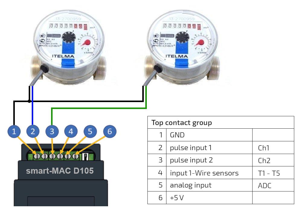
42 Water Meter Connection Diagram
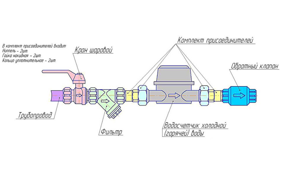
when installing the meter, make sure the arrow on the meter body is going the same direction as the water flow. For V3040BSPT-15 WSI.5 Meter BSPT use 1.5" BSPT pipe and fittings. Installation of the \/3050 WS2 Meter NPT Assembly can be accomplished with 2" NPT pipe or by using a 21/2" groove lock coupling. Online applications, approvals and plans. Are you building or renovating and wondering where to start? Sydney Water Tap in is available 24/7. It's the quick, convenient way to request and review building plan approvals, purchase service and wastewater diagrams, apply for water connections or disconnections, and much more.
Older diagrams also show the point of connection to our wastewater system, easements over the land and other information for plumbers. For more help understanding the diagram, read our Help with your sewer service diagram fact sheet (376KB).
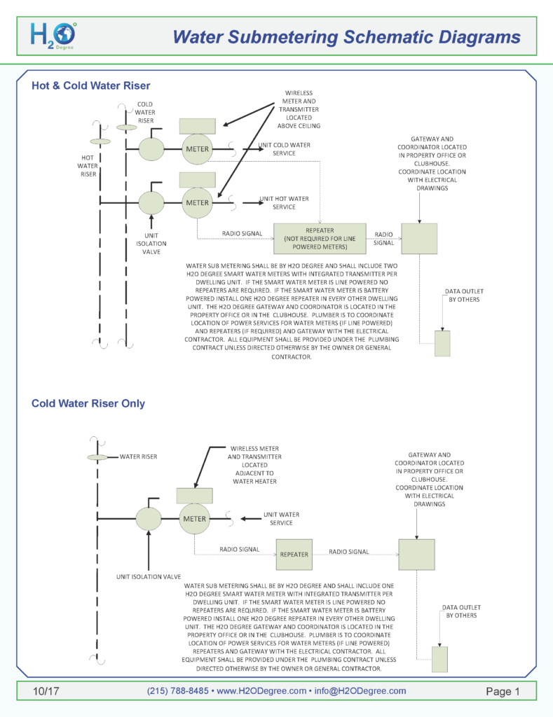
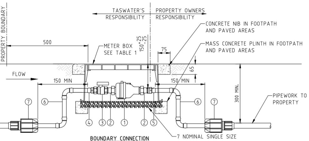
Water meter connection diagram
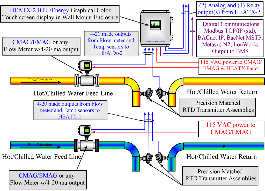
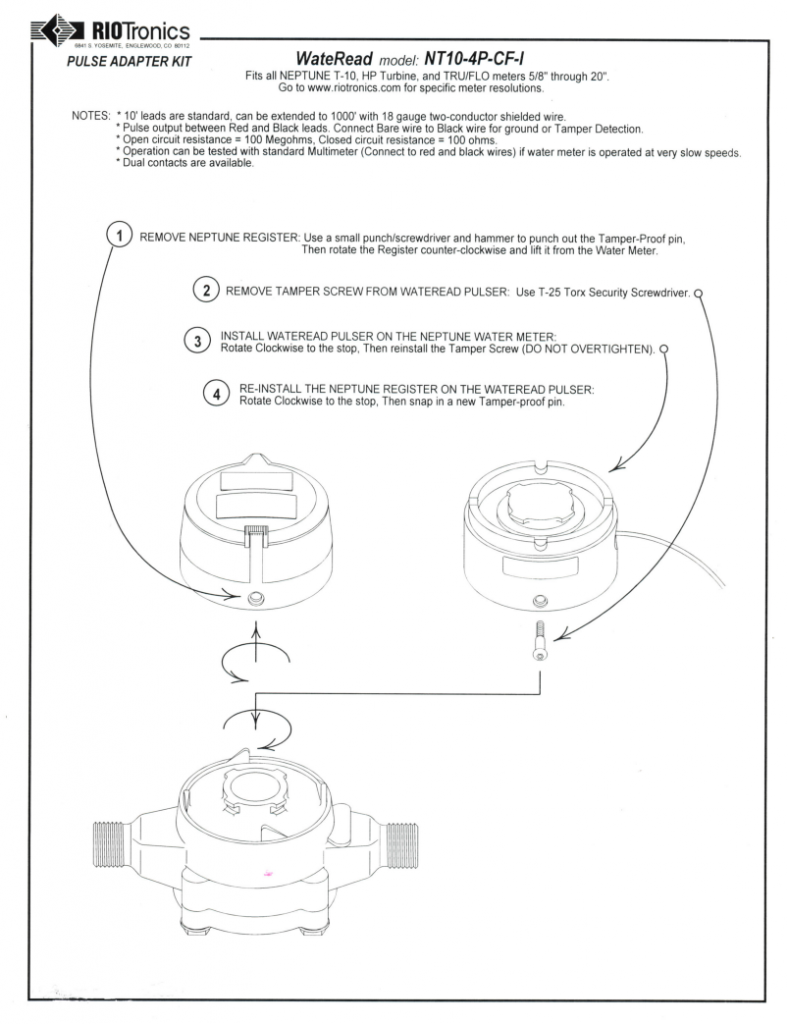
Neptune Water Meter Wiring Diagram 10.11.2018 10.11.2018 7 Comments on Neptune Water Meter Wiring Diagram The TRICON® transmitter provides an electronic interface to Neptune water meters electrical pulses at a rate corresponding to the rate of flow through the meter. Leave 12 inches extra wiring at each end for owner termination. 120V feed shall be 15A dedicated circuit from panel. Water Meter Wiring Diagram DATE Drawing Not To Scale 12/08/17 Date: 11/28/2017 Campus Facilities University Of Missouri REV See Appendix 1 - Diagram 2 (page 8) which shows an illustration of a typical single meter installation of in-line meter internal (not on manifold). Diagram 3 (page 9) shows, a meter carrier for a single and/or multiple internal meter installation (which can also be used on a multiple manifold).
Water meter connection diagram. INSTALLATION. • AMI INFRASTRUCTURE Install new meter; turn water on. Mount MXU to Sensus ECR (all variants). Green. Red. Black. for Sensus and Invensys Water Meters provides wiring information for use in connecting a STAR MTU to Sensus Step 2 – Select the wiring diagram that. for Sensus and Invensys Water Meters provides wiring information for use in connecting a STAR MTU to Sensus Step 2. Neptune Water Meter Wiring Diagram 10.11.2018 10.11.2018 7 Comments on Neptune Water Meter Wiring Diagram The TRICON® transmitter provides an electronic interface to Neptune water meters electrical pulses at a rate corresponding to the rate of flow through the meter. Meter 1/4" 74 micron / 200 mesh. Meter 1/2" - 2" 250 micron / 60 mesh. Meter 3" - 4" 400 micron / 40 mesh. 5. Note: The Flowmeter can accept flow in any. direction. 6. The meter can be installed in any orientation as long as the meter shafts are in a horizontal plane. (Refer to diagram below for correct installation). Note: Sep 30, 2004 · LANL Standard Drawings and Details either (1) depict required format/content or (2) are templates that are completed by a Design Agency (LANL or external AE) for a design drawing package, in a manner similar to specifications.
Sensus Products WP Dynamic 50 °C Water Meter from how to install water meter diagram In case the gauge is not functioning, retest the connections. An air fuel gauge will enable you to monitor the changes in oxygen content in the air your car or truck is breathing so you can make adjustments to prevent damage to your car or maybe to stop poor. d-23 new copper 1-inch water service standard meter vault d-24 new copper 1.5 n. & 2 in. water service standard meter vault d-25 3 inch, 4 inch, 6 inch, 8 inch & 12 inch meter vaults d-26 12 inch meter vault with check valve d-27 typical meter installation for 1 inch water service with lawn hydrant and backflow preventor The below diagram shows how a 20mm water meter and service line should be positioned in relation to the front boundary line and the finished ground level. Please note the clearances required. The new location will need to have these minimum clearances when relocating your water meter. This helpful instructional video will help you learn how to correctly install a water meter. For more information, http://austintexas.gov/department/taps
Complete this form for all water and sewer connections and disconnections, water main drilling and pre-laid services drilling (minor works), water meter installation, recycled water connections and recycled water meter installation applications. You can select multiple application types when completing this form. W-31 Typical 1 ½ "- 2" Water Meter Box Installation W-32 Typical 4" Water Meter Vault W-33 Typical 6" thru 10" Water Meter Vault W-34 Fire, Domestic & Irrigation Options Schematic W-35 Irrigation Tap on New and Existing Services W-35T Termination of Irrigation Meter W-36 Reduced Pressure Backflow Preventer. Dec 20, 2017 · Using a small container we can carry water, a 5V pump is also placed in the container and the whole container is placed on top of a servo motor so that we can control the direction in which the water has to be sprayed. Let’s proceed with the connections now Circuit Diagram: The complete circuit diagram for this Fire Fighting Robot is given below the meter relocated outside the customer's facility near both the SMART production meter and the utility disconnect switch. Note 2 * Must have a cellular connection at meter location. * Meter will have bi-directional interval recording capabilities. * Secondary metering CTs/VTs may be required. Note 3
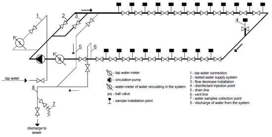
refer to the Annexure - Standard Water Meter Connection Schematic Diagram - Types 1 to 5 Diagrams and Types 3A to 6 (TSS-001 and TSS-002). 3.2.2 Connection to the Water Main, Property Water Service and Water Meter Sizing for Dual Occupancies and Granny Flats Developments (new and reconfigured) which fall between a single residential dwelling
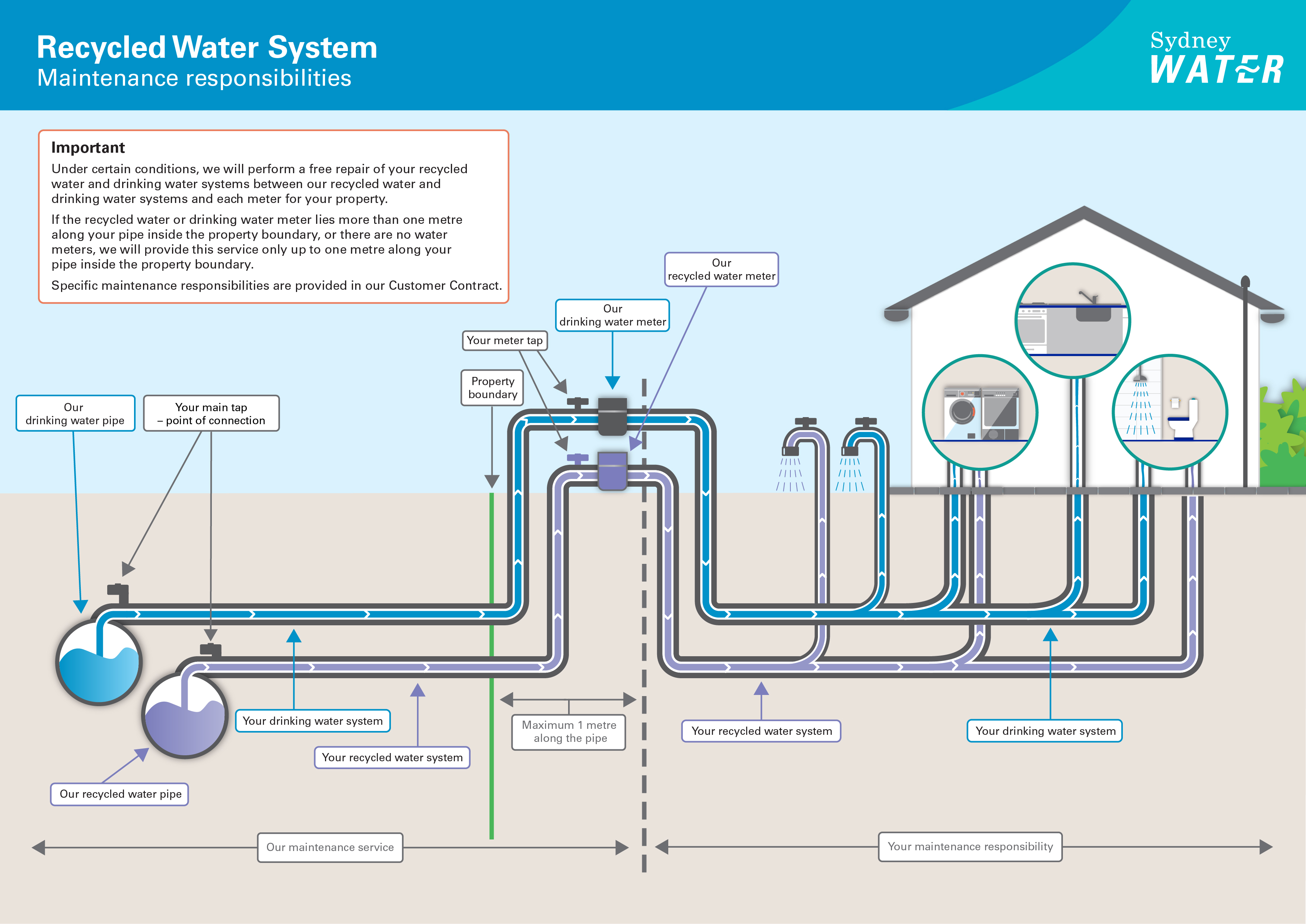
Find out how to connect to our water, wastewater and stormwater systems by reading our connecting to our systems policy (291 KB). Once you have a connection, there are parts of each system that we look after and parts you are responsible for. Have a look at the diagrams below to find out more about maintenance responsibilities.
TYPICAL WIRING OF METER SOCKET FOR SINGLE PHASE, THREE WIRE OVERHEAD SERVICE A. GENERAL NOTES: • Service entrance line and load conductors, conduit straps, weatherhead, lock nuts, bushings, connectors, and miscellaneous mounting hardware furnished and installed by customer.
Water Meters. Water Meters;. Call Us Today: 800-654-0821. Wiring Diagrams. Not all installations are created equal. Search through our list of wiring diagrams to find the right one for your job. Single Phase - Form 2S for 120V Circuit. FORM 2S Need a meter for a 120 volt circuit? Order our 240 volt meter. This diagram shows how to wire it...
The notion of water on Mars preceded the space age by hundreds of years. Early telescopic observers correctly assumed that the white polar caps and clouds were indications of water's presence. These observations, coupled with the fact that Mars has a 24-hour day, led astronomer William Herschel to declare in 1784 that Mars probably offered its inhabitants "a situation in many respects similar.
One electrode probe is (F) with 6V AC is placed at the bottom of the tank. Other probes are placed step by step above the bottom probe. When water is rising the base of each transistor gets electrical connection to 6V AC through water and the corresponding probe.
Connecting the property side of a water line to a meter requires a few basic plumbing skills and a few basic tools. It also requires an attention to detail when making that connection. Improper connections can cause leaks and damage to the meter or even to the water line. These conditions can lead to costly repair and water bills.
From Large and Small Public Water Systems to Paper Mills, Hospitals, and Food Processing Plants, HydroCorp has the range of experience you want when protecting your drinking water supply. Our specialists are experienced with facility infrastructure across all industries and will quickly identify the potential hazards that can impact health and.
May 04, 2021 · Sewer Meter Station Design Guide Electrical Plan and Details: E-2: Sewer Meter Station Design Guide RTU Installation Wiring Diagrams: E-3: Sewer Meter Station Design Guide Electrical General Notes: MS-1: Sewer Meter Station Design Guide Piping, Structural and Details: MS-2: Magmeter with no Venturi Piping, Structural and Details
A water meter is generally ¾ inch, but there are exceptions. Get a backflow preventer and a thermal expansion control device and place them on the end of the pipe according to plumbing code. Step Four - Obtain the Meter. You'll need to get a water meter from either the municipality or by purchasing it online.
remove the water from the water meter as the backflow preventer will not allow the meter to drain. If the meter is exposed to freezing conditions, the sacrificial frost plate (#2 on the diagram) will break to prevent damage to the meter. Frost plate repairs must be completed by the municipality and the costs are billed to the home owner.
terminals in the flow meter. See Figure 7. A wiring diagram decal is located adjacent to the field wiring terminals within the FUSION enclosure. If the flow meter is only to be utilized as a flow rate indicator or totalizer, no further wiring will be required. Skip to the Flow Meter Configuration section of this manual (see page 19).
1.3 WATER METER The water meter shall meet or exceed the following requirements: Volumetric rotary piston principle of measurement 15mm, 20mm or 25mm Class C, 114mm plastic rotary piston meter with liquid sealed mechanical transmission/flow with direct reading counter, high reliability, high precision Conform to NRCS 1529-1
Leave 12 inches extra wiring at each end for owner termination. 120V feed shall be 15A dedicated circuit from panel. Water Meter Wiring Diagram DATE Drawing Not To Scale 12/08/17 Date: 11/28/2017 Campus Facilities University Of Missouri REV
This manual provides procedures on how and where to obtain a water meter, fire hydrant permit, water service connection and so on. Included also are guidelines for handling different water servicing scenarios. This manual also describes in detail some of the most frequently asked questions pertaining to the water supply bylaw.
See Appendix 1 - Diagram 2 (page 8) which shows an illustration of a typical single meter installation of in-line meter internal (not on manifold). Diagram 3 (page 9) shows, a meter carrier for a single and/or multiple internal meter installation (which can also be used on a multiple manifold).
Water Meter Wiring Diagram Harrietta Marchand. October 23, 2021 October 23, 2021. Automatic Water Level Controller Wiring Diagram Electrical Circuit Diagram Diagram Water Pump Motor. Designing Electrical Control Board In 2021 Electrical Switches House Wiring Home Electrical Wiring .
Check the water meter for the proper direction of flow. The meter will have some kind of flow direction indicator located on the top or sides of the meter. Then install the new meter and rubber gaskets. For proper installation, never use a wrench to start the thread connections. Always start the meter connections by hand to make sure that the.














0 Response to "42 Water Meter Connection Diagram"
Post a Comment