42 Shunt Trip Breaker Diagram
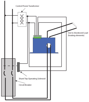
In this video i complete explain the shunt trip breaker wiring diagram or installation of shunt trip circuit breaker. In the shunt trip breaker there is a shunt trip coil that trips the breaker. It is supplied with yellow and white secondary leads connected to a secondary connector plug (see figure 2). Shunt coil, mccb control by shunt coil. 12+ Mccb Shunt Trip Wiring Diagram. In the diagram a mccb (molded case circuit breaker) shown which is wired for 3 phase system. In industrial state, electric operator duty is to operate the machinery and his duty is on the front of main panel board. Let's learn the circuit functioning in details.
Feb 24, 2012 · The relay must be operated in only those conditions for which relays are commissioned in the electrical power system. There may be some typical condition during fault for which some relays should not be operated or operated after some definite time delay hence protection relay must be sufficiently capable to select appropriate condition for which it would be operated.
Shunt trip breaker diagram
MicroLogic trip systems use a set of current transformers (called CTs or sensors) to sense current, a trip unit to evaluate the current, and a tripping solenoid to trip the circuit breaker. Adjustable rotary switches on the trip unit allow the user to set the proper overcurrent or equipment ground-fault current protection required in the. Shunt Trip Breaker Wiring Diagram For Ansul System - You almost certainly already know that square d shunt trip breaker wiring diagram has become the hottest topics over the internet today. Based on the information we took from google adwords, square d shunt trip breaker wiring diagram has very much search online web engine. The shunt trip breaker is a combination of the shunt trip accessory and the main circuit breaker. This installs on the main breaker to add protection to your electrical system. This adds security to your electrical system as it manually or automatically cuts the electric supply in your circuit. This accessory can help prevent short circuits and.
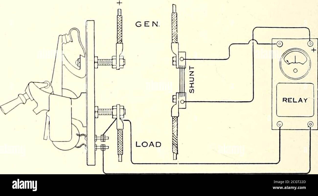
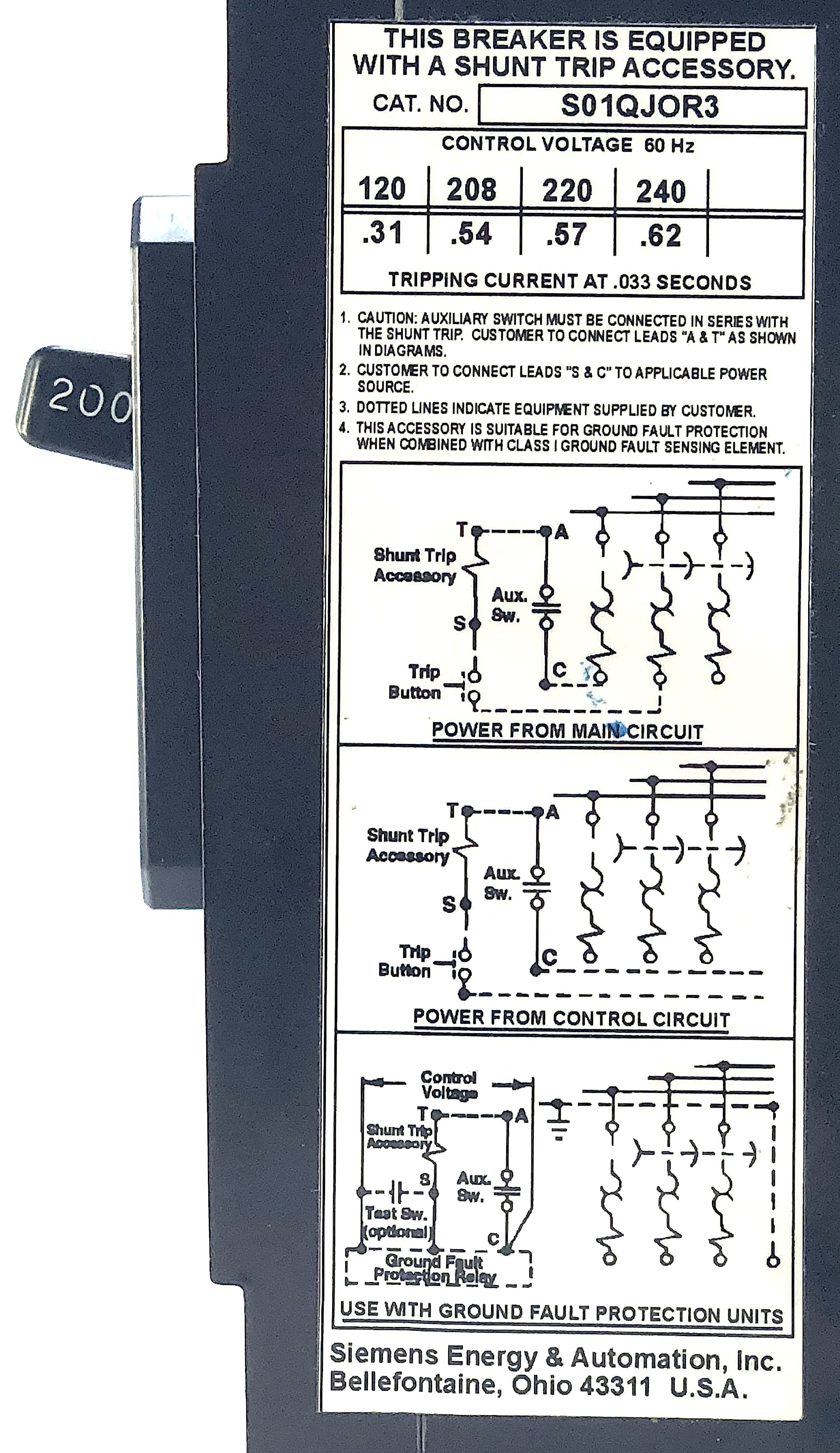
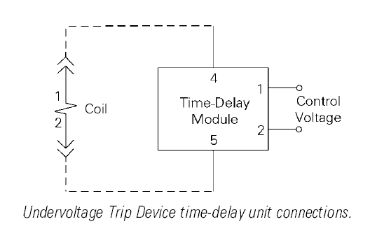
Shunt trip breaker diagram. Siemens Shunt Trip Breaker Wiring Diagram Download. Assortment of siemens shunt trip breaker wiring diagram. A wiring diagram is a streamlined conventional pictorial representation of an electric circuit. It shows the elements of the circuit as streamlined shapes, and the power and signal connections between the tools. The shunt breaker is 3 pole. In the above MCCB shunt trip breaker wiring diagram. 120v Shunt Trip Wiring Diagram wiring diagram is a simplified normal pictorial representation of an electrical circuit. Emergency Power Off EPO is the capability to. Shunt trip breaker wiring diagram this post is about the single wiring diagram of mccb shunt trip. As you know that Safety is important in electricity works. Today i am writing about shunt trip breaker wiring diagram which related with safety and protection of electricity. As you know that electricity is dangerous but it's become more dangerous when it's upgrade from the 220 volts to 3 phase 440 volts. The shunt trip breaker is a combination of the shunt trip accessory and the main circuit breaker. This installs on the main breaker to add protection to your electrical system. This adds security to your electrical system as it manually or automatically cuts the electric supply in your circuit. This accessory can help prevent short circuits and.
Mar 24, 2015 · Elevator Shunt Trip is a function that involves the fire alarm system via heat detectors, shunting the breaker that controls the elevator equipment (typically set to activate 5 degrees before the actual automatic sprinkler head pops.). This in turn powers down the elevator equipment before any automatic sprinkler water is released. Figure 2. Shunt Trip Device Wiring Diagram. Dec 05, · In these cases, a shunt-trip breaker is installed in the circuit feeding the elevator controls, and the fire alarm system sends a trip signal if it detects waterflow from the sprinkler system. Elevator Shunt Trip Wiring We have created an easy to follow document for the proper wiring method. Understanding the Shunt Trip Breaker Wiring Diagram. Before wiring your shunt trip breaker to your safety control system or switch, you need to first understand its wiring diagram. This is a crucial part of the installation—that's why you can't skip it and need to be more careful with it. Shunt Trip Breaker Wiring Diagram For Ansul System - You almost certainly already know that square d shunt trip breaker wiring diagram has become the hottest topics over the internet today. Based on the information we took from google adwords, square d shunt trip breaker wiring diagram has very much search online web engine.
Tutorial for wiring a shunt trip QO™ (and QOB) Circuit Breaker. Shunt trips (accessories) in QO™ breakers are factory installed only and can not be added to. This diagram can help clear up the wiring in of fire alarm modules and This document includes two methods both based on the supervision an addressable relay module (FRM-1) to operate the shunt trip breaker directly. 2. Executive Summary. Emergency Power Off (EPO) is the capability to. operate on activation of smoke detectors and also by. Shunt Trip Breaker Wiring Diagram - Diagram Stream from ww2.justanswer . A shunt trip breaker is a type of circuit breaker that, in addition to automatically tripping during an electrical surge and cutting off power, also can be triggered by a separate electrical signal to. Advertisement the shunt trip, shown in figure 22, allows the. Shunt breaker wiring diagram Wiring Diagram for Shunt Trip Breaker Copy Best Shunt Trip Breaker Wiring Diagram 71 for Chromalox Heater. If not bad breaker. Power the PR-1 with the shunt trip control circuit and connect your addressable monitor module to the Common and Normally Open leads.
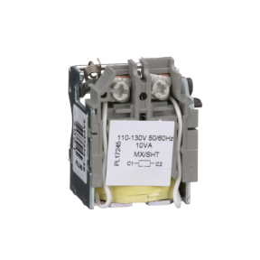
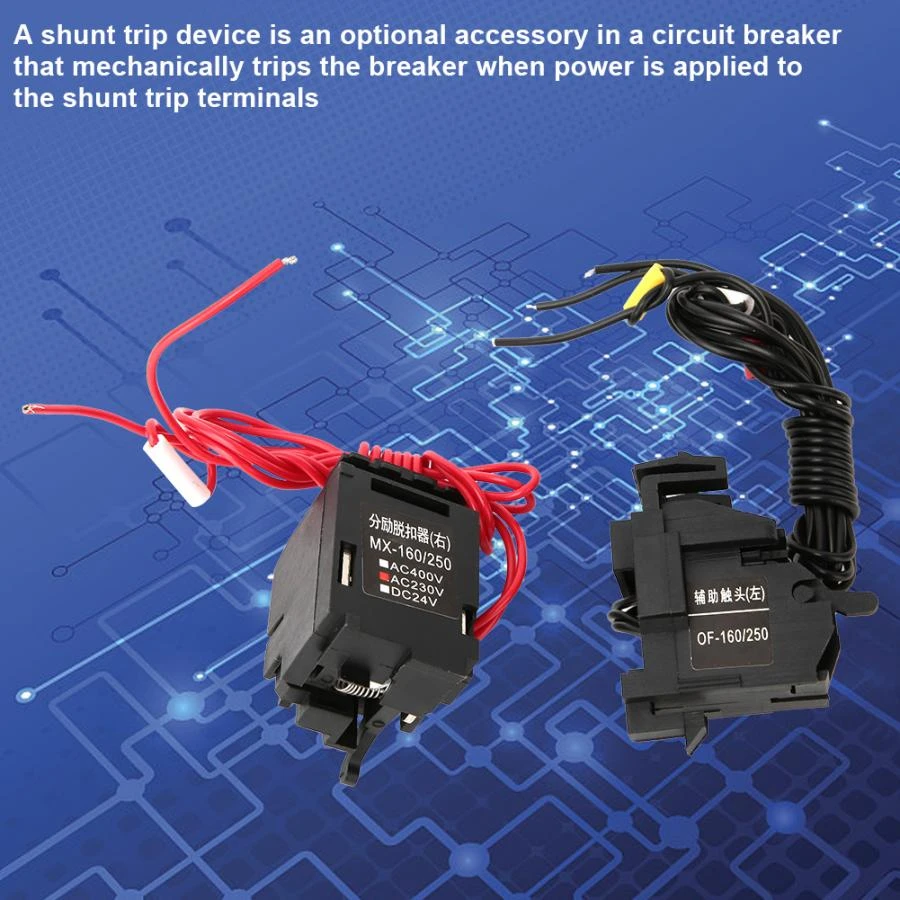
Here is some images of shunt coils and after that we will discuss the shunt trip breaker wiring diagram with image + symbol diagram. Now lets how to wire shunt trip device (accessory), its too simple as i shown in above shunt trip device images that a shunt coil have only to wires , just like a magnetic contactor or magnetic relay coil.
The Shunt Trip allows a circuit breaker to be tripped remotely by applying a voltage to the Maximumwire leads. The unit consists of an intermittent solenoid with a tripping plunger and a cutoff switch, and is mounted so that when the solenoid is energized, the trip lever presses against the trip bar and trips the circuit breaker. As the breaker
Both the overload trip action and the short-circuit trip action of breakers with Digitrip electronic trip units are achieved by the use of current transformers and solid-state circuitry that monitors the current and initiates tripping through a flux shunt trip when an overload or a short circuit is present. All multiple-pole circuit
Size: 65.77 KB. Dimension: 1594 x 696. See also Packard C230b Wiring Diagram Gallery. DOWNLOAD. Wiring Diagram Images Detail: Name: siemens shunt trip breaker wiring diagram – Siemens Shunt Trip Breaker Wiring Diagram Unbelievable Heavenly And. File Type: JPG. Source: techreviewed . Size: 737.05 KB.
The Eaton MV VCP-W Circuit Breaker is renowned for its ease of handling and maintenance. This OEM-friendly product is ideal for short-circuit protection and has numerous design variations to ensure all possible applications are supported. Eaton's patented V-FLEX System features fewer moving parts, which reduces friction and wear associated with rolling/sliding designs, and increases product.
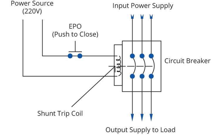
In the above MCCB shunt trip breaker wiring diagram. The incoming 3 phase 4 wire system supply shown. The shunt breaker is 3 pole. Which is used for the 3 phase system. But the coil of the shunt is 220 VAC. So neutral is required also. The neutral wire is connected to the shunt coil. And line wire is controlled with a kill switch.
Controlling the Masterpact MTZ Circuit Breaker Open/Closed Status Selection of Coils Shunt Close (XF), Shunt Trip (MX), and Undervoltage Release (MN) with Diagnostic and Communicating Coils
The major components of a simple control circuit are: the rectifier unit, the closing relay, the closing coil, the tripping coil, the auxiliary contacts, and the circuit breaker control switch. - just 4 compact frame sizes. Shunt Trip Circuit Breaker (4) Under-voltage Trip activates the trip coil of a circuit breaker. 00 1 Charging Motor 0.
MicroLogic trip systems use a set of current transformers (called CTs or sensors) to sense current, a trip unit to evaluate the current, and a tripping solenoid to trip the circuit breaker. Adjustable rotary switches on the trip unit allow the user to set the proper overcurrent or equipment ground-fault current protection required in the.
The generator breaker have a built-in mechanical delay system with which the opening time is prolonged by approx. 30 ms. In the basic version of the circuit-breaker, the spring energy store is charged manually. The operating mechanism can optionally be fitted with a charging motor. Very compact dimensions Fixed and withdrawable versions
Siemens Shunt Trip Breaker Wiring Diagram Sample. siemens shunt trip breaker wiring diagram - Architectural wiring layouts show the approximate locations as well as affiliations of receptacles, lights, and permanent electrical services in a structure. Interconnecting cord routes might be shown around, where certain receptacles or fixtures need to be on a typical circuit.
er is the same form-factor/mounting as QJ breaker for easy retrofit. Design enhancements include: b Trip unit ratings from 100A to 250A. b Field installable internal accessories – shunt trip, aux switch or shunt/aux combo. b Two accessory pockets in 3-pole breakers. One accessory pocket in 2-pole breakers. b High in-rush current capability.
Fig. 1-1 Shunt Trip Installed in Q-Frame Circuit Breaker GENERAL INFORMATION The shunt trip (Fig. 1-1) provides remote controlled elec- trical tripping for the circuit breaker. It consists of an inter- mittent rated solenoid with a tripping plunger and a cutoff switch attached to a plug-in module. The plug-in module
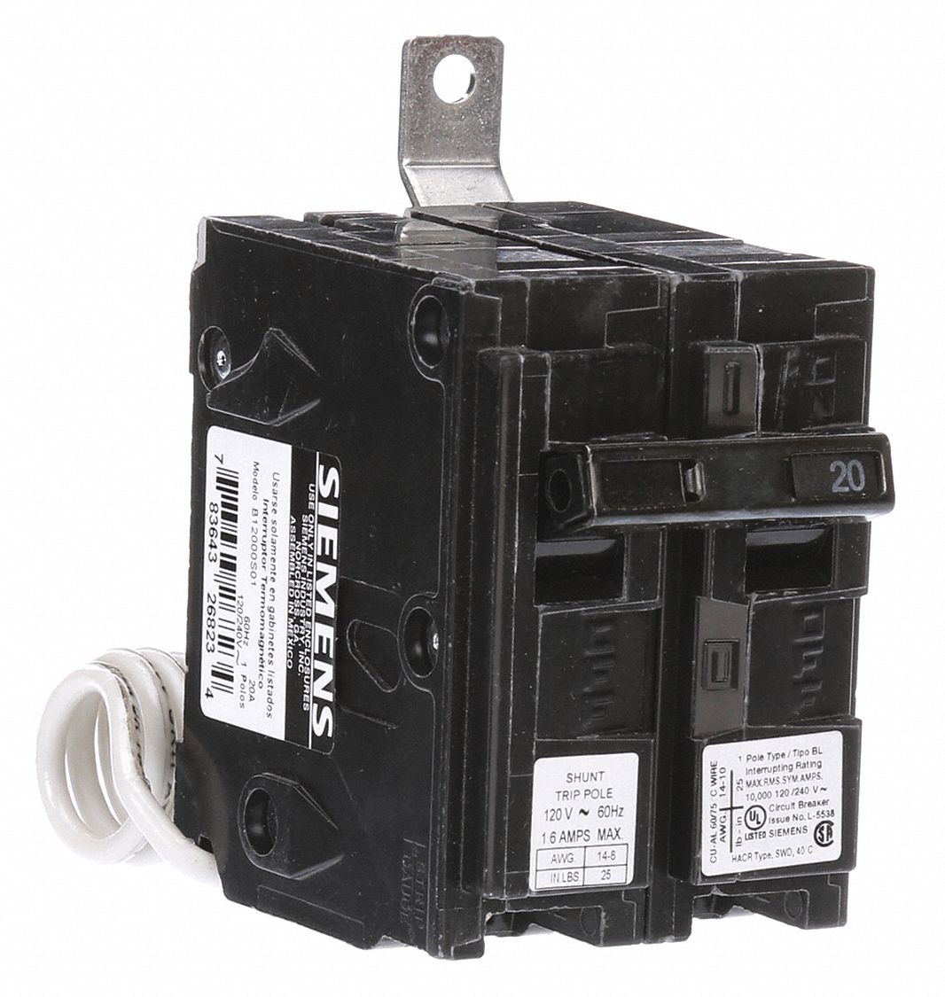
Shunt Breaker Wiring Diagram Madcomics. Fixed Circuit Breakers. Qob1201021 Mini Circuit Breaker Qo 20a 1 Pole 120 240vac 10ka Bolt On Mount Ac Shunt Trip Schneider Electric Canada. Schneider Shunt Trip Voltage Release Mx 208 277v 60hz 220 240v 50. Abb S5n Breaker Wiring Second Life Storage Solar.
Siemens Shunt Trip Breaker Wiring Diagram - wiring diagram is a simplified customary pictorial representation of an electrical circuit. It shows the components of the circuit as simplified shapes, and the talent and signal friends together with the devices. A wiring diagram usually gives opinion virtually the relative outlook and promise of.
General trip indication '+', when tripped by shunt release, overload release, short-circuit release or by the residual-current release due to residual-current. Can be used with NZM1, 2, 3 circuit-breaker: a trip-indicating auxiliary contact can be clipped into the circuit-breaker.
Square D Shunt Trip Breaker Wiring Diagram. Collection of square d shunt trip breaker wiring diagram. A wiring diagram is a simplified standard photographic depiction of an electric circuit. It shows the parts of the circuit as simplified forms, and also the power and also signal connections between the tools. A wiring diagram normally provides info concerning…
Shunt Trip Wiring Diagram Square D Gallery. shunt trip wiring diagram square d - Building electrical wiring representations show the approximate areas and affiliations of receptacles, illumination, and also long-term electric services in a building. Adjoining cable paths may be revealed about, where certain receptacles or components must be on a common circuit.
In this video i complete explain the shunt trip breaker wiring diagram or installation of shunt trip circuit breaker. In this video i also shown with video.
shunt trip, and overcurrent trip switch warning (1)only qualified electrical personnel should be permitted to work on the equipment. (2)always de-energize primary and secondary circuits if a circuit breaker cannot be removed to a safe work location. (3)drawout circuit breakers should be levered (racked) out to the disconnect position.
This is a very simple wiring diagram. You can see just there is an EPO or Emergency Power Off button is connected in series with the shunt trip coil of the MCCB. It is a normally open switch, when you push, it will close the circuit. So the shunt trip coil will get power supply and it will trip the MCCB. Note that, the shunt trip coil is rated.
Collection of cutler hammer shunt trip breaker wiring diagram. A wiring diagram is a simplified traditional pictorial depiction of an electrical circuit. It shows the parts of the circuit as streamlined shapes, and the power and signal connections between the tools.
Cutler Hammer Shunt Trip Breaker Wiring Diagram. Madcomics shunt trip breaker wiring br120st eaton type br brkr 20a 1 pole 120 240v 10k w installation instructions for series g n frame circuit breakerolded case switches br230st thermal magnetic bab1020s bolt on breakers power distribution platt electric supply snt1lp03k cutler hammer div of.














0 Response to "42 Shunt Trip Breaker Diagram"
Post a Comment