42 In The Diagram To The Right The Current Through
9) The diagram shows a straight wire carrying current i to the right in a uniform magnetic field. The magnetic force on the wire is down the paper as indicated by the arrow, but the magnetic field is not shown. Of the following possibilities, the direction of the magnetic field is: & A) into the page B) opposite to the direction of C) out of. The diagram to the right represents an electric circuit consisting of four resistors and a 12-volt battery. 6) What is the equivalent resistance of the circuit shown? 7) What is the current measured by ammeter
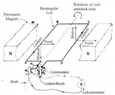
The current in the wire produces a magnetic field. At point 1 this external field is OUT of the page. At point 2 the external field is INTO the page. This magnetic field passes through the loop and is the source of magnetic flux through the coil. As the loop slides by position 1, the flux through the loop is INCREASING and it is Pointing
In the diagram to the right the current through
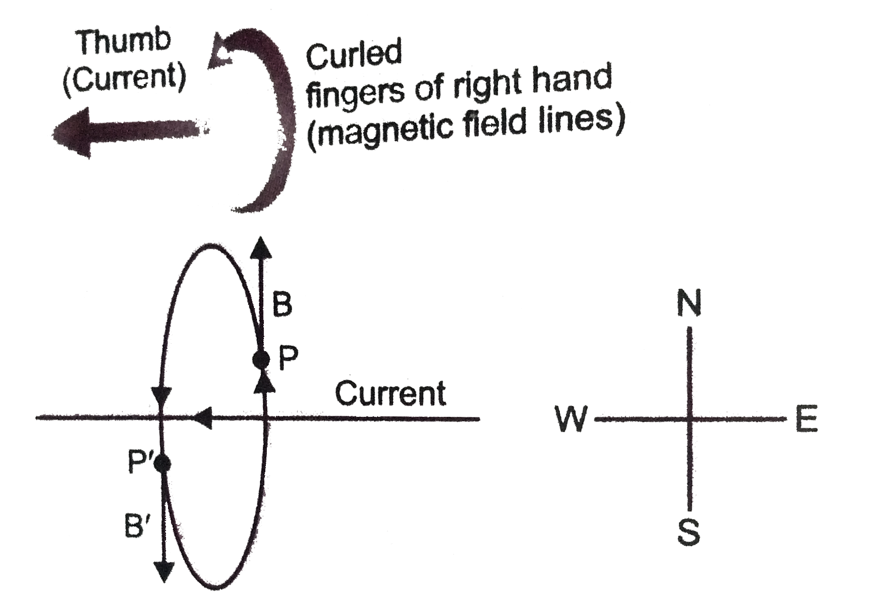
Two long parallel wires placed side-by-side on a horizontal table carry identical size currents in opposite directions. The wire on your right carries current directly toward you, and the wire on your left carries current directly away from you. From your point of view, the magnetic field at a point exactly midway between the two wires through the resistor, which is the same current that flows through the capacitor because it is a series circuit. Note that this is consistent with the fact that capacitor current changes instantaneously. The left diagram (large angle) corresponds to a circuit that is dominated by capacitive reactance, in which the current is nearly 90 degrees. Let the current pass through the loop clockwise. Apply the right-hand rule to find out the direction of the magnetic field inside and outside the loop. Ans: In the following diagram the current is flowing clockwise. If we are applying right hand thumb rule to the left side of the loop then the direction of magnetic field lines inside the loop.
In the diagram to the right the current through. diagram is shown in Figure 10.2.3: Figure 10.2.3 Equivalent circuit diagram for the moving bar The magnetic force experienced by the bar as it moves to the right is 22 ()ˆ(ˆ) ˆ B B lv ˆ Il B IlB R ⎛⎞ =×−=−=−⎜ ⎝⎠ F j ki⎟ G i (10.2.6) which is in the opposite direction of v G. For the bar to move at a constant velocity, the net The diagram shows two current-carrying wires, P and Q, that both lie in the plane of the paper.. A wire carrying a current \(I\) is at right angles to a uniform magnetic field of strength B. A magnetic force F is exerted on the wire.... The current through X is greater than that through Z. B. 2. The flux through the top loop is upward and increasing. 3. To oppose the increase, the field of the induced current must point downward. 4. From the right-hand rule, a downward field needs a cw current. 5. The ccw current in the lower loop makes the upper face a north pole. The cw induced current in the upper loop makes the lower face a. 46. In the circuit diagram shown, what is the current through the 4.0-ohm resistor? A. 1.0 ampere B. 0.33 ampere C. 3.0 amperes D. 48 amperes 47. The diagram here shows a resistor of 5 ohms and a resistor of 10 ohms connected in parallel in a circuit. What is the total resistance of the circuit? A. less than 5 ohms B. 5 ohms C. 15 ohms D.
Base your answers to questions 38 through 41 on the diagram and information below and on your knowledge of physics. A 15-ohm resistor, 30-ohm resistor, and an ammeter are connected as shown with a 60-volt battery. 38.If another resistor were added in parallel to the original circuit, what effect would this have on the current through resistor R1? In the diagram, if the current through R 1 is 5 A up and if the current through R 3 is 3 A up, what is the current in R 2? Expert Answer 100% (8 ratings) Previous question Next question. through the resistor, which is the same current that flows through the capacitor because it is a series circuit. Note that this is consistent with the fact that capacitor current changes instantaneously. The left diagram (large angle) corresponds to a circuit that is dominated by capacitive reactance, in which the current is nearly 90 degrees. Click here👆to get an answer to your question ️ A current of 0.1 A flows through a 25 Ω resistor represented by the circuit diagram. The current in the 80 Ω resistor is
the current through and potential difference across Base answers to questions Il through 13 on the information and diagram below. A 15—0hm resistor, R , And 30-0hm resistor, arc to be connected in parallel between points A and B in a circuit containing a 90-volt battery. 90. v 11. Completc the diagram above to show the two resis- Let the current pass through the loop clockwise. Apply the right-hand rule to find out the direction of the magnetic field inside and outside the loop. Ans: In the following diagram the current is flowing clockwise. If we are applying right hand thumb rule to the left side of the loop then the direction of magnetic field lines inside the loop. calculus. Two batteries of emf ℰ and internal resistance r are connected in parallel to a load of resistance R as shown in the diagram below. Write Kirchhoff's equations for this circuit. Determine the current through the load. Show that the power dissipated by the load is a maximum when R = ½r. A direct current circuit may contain capacitors and resistors, the current will vary with time When the circuit is completed, the capacitor starts to charge The capacitor continues to charge until it reaches its maximum charge (Q = Cε) Once the capacitor is fully charged, the current in the circuit is zero

A Current Through A Horizontal Power Line Flows In East To
Science. Physics. Physics questions and answers. The diagram to the right shows a current through a solenoid sitting in a magnetic field. Relative to the page, how will the coil move due to the magnetic field? v tv B 100 TV O to left to right O to top of page) to bottom rotate clockwise rotate counterclockwise cannot be determined.
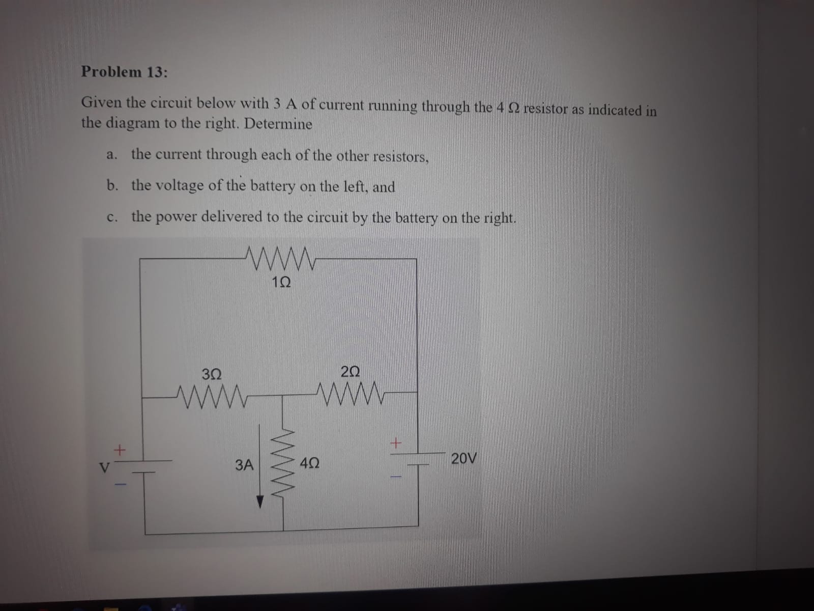
Solved 7 Given The Circuit Below With 3 A Of Current
12.What is the current measured by ammeter A? 13.A 9.0-volt battery is connected to a 4.0-ohm resistor and a 5.0-ohm resistor as shown in the diagram below. A)4.0 A B)1.8 A C)1.0 A D)2.3 A What is the current in the 5.0-ohm resistor? 14.Ammeters A1, A2 and A3 are placed in a circuit as shown below.

Right Hand Rule For Current Carrying Wire Ap Physics 2
As Q increases I decreases, but Q changes because there is a current I. As the current decreases Q changes more slowly. I = dQ/dt, so the equation can be written: ε - R (dQ/dt) - Q/C = 0 This is a differential equation that can be solved for Q as a function of time. The solution (derived in the text) is: Q(t) = Q o [ 1 - e-t/τ]

Example E 42 V A Right After S Is Closed Find The Current
current would go down the path of no resistance leaving no current passing through the lamp (short circuit). Questions 9 and 10 refer to the following: A 50.-ohm resistor, an unknown resistor R , a 120-volt source, and an ammeter are connected in a complete
Electric Circuits Review Answers 3
The diagram shows a straight wire carrying current i to the right in a uniform magnetic field. The magnetic force on the wire is down the paper as indicated by the arrow, but the magnetic field is not shown. Of the following possibilities, the direction of the magnetic field is: out of the page
Solved 7 Given The Circuit Below With 3 A Of Current
11.2 Ohm's Law (ESBQ6) Interactive Exercise 11.2. Try the interactive questions. Three quantities which are fundamental to electric circuits are current, voltage (potential difference) and resistance. To recap: Electrical current, I, is defined as the rate of flow of charge through a circuit. Potential difference or voltage, V, is the amount of.

Series Rlc Circuit And Rlc Series Circuit Analysis
Answer: The (–) particle is moving at right angles to the field. By the right-hand rule, the direction "v cross B" is into the page, but the particle has a negative charge q, so the force is out of the page. B A negative particle and a positive particle are moving with certain velocities in a constant, uniform magnetic field, as shown.
Answered 2 3 4 7 Using The Diagram To The Bartleby
of current through a flashlight bulb for 5.0 min-utes, while a 1.5-volt, C cell supplies 750 mil-liamperes of current through the same flashlight bulb for 20. minutes. Compared to the total charge transferred by the AAA cell through the bulb, the total charge transferred by the C cell through the bulb is (1) half as great (3) the same

The Diagram Below Shows A Circuit With One Battery And 10
Place ammeters in series at a location such that the current through each resistor can be measured and in a location such that the overall current in the circuit can be measured. On the schematic diagram, use an unbroken arrow to indicate the direction of conventional current.
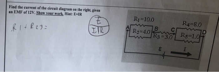
Solved Find Current Circuit Diagram Right Given Emf 12v
The circuit diagram 31 on the right shows how you can investigate the variation of current through a resistance (or any component) when you vary the potential difference. Current–potential difference graphs are used to show how the current through a component varies with the potential difference across it.
D52 2047 Ac80v 300v Built In Ct Din Rail Multi Fungtion Meter 100a
If n electrons pass through the cross-section of a conductor in time t, the total charge that passes through the conductor is then, Q = n×e. Electric Current and Circuit Diagram Elements. The schematic diagram represents the different components of a circuit; this is the circuit diagram. These symbols represent the common electrical components.
Solved Problem 12 Determine The Current Through Each
The direction in which the induced emf drives current around a wire loop can be found through the negative sign. However, it is usually easier to determine this direction with Lenz's law, named in honor of its discoverer, Heinrich Lenz (1804-1865). (Faraday also discovered this law, independently of Lenz.)
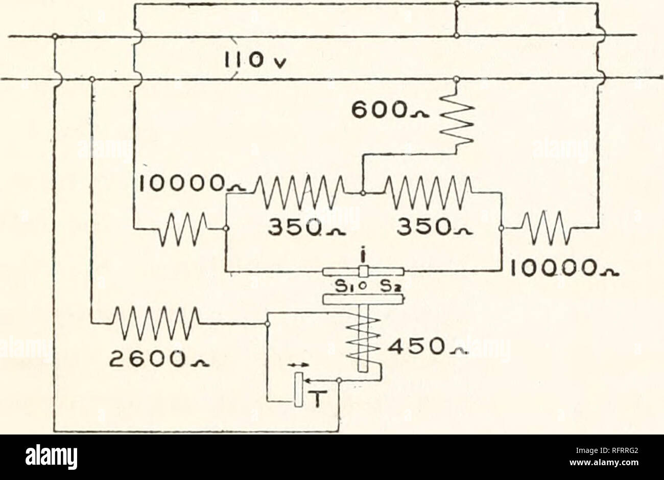
Carnegie Institution Of Washington Publication Fig 21
series to a voltage source. When the current through the 10.-ohm resistor is 2.0 amperes, what is the current through the 20.-ohm resistor? (1) 1.0 A (3) 0.50 A (2) 2.0 A (4) 4.0 A 14. In the circuit diagram below, what are the correct readings of voltmeters V1 and V2? (1) V1 reads 2.0 V and V2 reads 4.0 V (2) V1 reads 4.0 V and V2 reads 2.0 V

Entity Relationship Diagram Erd Er Diagram Tutorial
27. In the diagram at the right, electron current is passed through a solenoid. The north pole of the solenoid is nearest to point (1) A (3) C (2) B (4) D 28. The diagram below shows an electron current in a wire loop. What is the direction of the magnetic field at the center of the loop? (1) out of the page (3) clockwise (2) into the page (4.
Solved En Hw A Model For Circuits Part 3 Multiple Batteries
Two long parallel wires placed side-by-side on a horizontal table carry identical size currents in opposite directions. The wire on your right carries current directly toward you, and the wire on your left carries current directly away from you. From your point of view, the magnetic field at a point exactly midway between the two wires
94 The Diagram At Right Shows Three Resistors R1 R2 And R3
circuit to the right. R1and R2are in series and are replaced by R12 = R1 + R2. Now R12and R3are in parallel and can be replaced by R, where 1/R = 1/R12+ 1/R3. If R1 = R2 = R3 = 1 Ω, then R12 = 2 Ω and R = (2/3) Ω. If a 6 V battery is connected across points A and B, then the current flowing in the circuit is I = V/R = 9 A.
Arus Cabang Mana Yang Akan Menjadi Pembacaan Ammeter Ketika
current? (a) clockwise (b) counter-clockwise (c) no induced current ÎIf a coil is rotated as shown, in a B field pointing to the left, in what direction is the induced current? (a) clockwise (b) counter-clockwise (c) no induced current Upward flux through loop decreases, so need to create upward field Flux into loop is increasing, so

A Gate Current During The Positive And Negative Stresses
right through the surrounding loop. As the current in the solenoid increases there is more field and more flux to the right through the loop. There is an induced current in the loop that will oppose the change by creating an induced field and flux to the left. This requires a counterclockwise current when seen from the left end of the solenoid.

A Current Through A Horizontal Powerline Flows In East To West Direction What Is The Direction
Answer: E. Current is the ratio of charge to time. The quantity of charge passing through a cross section in 2 seconds is 10 C. The ratio of charge to time is. I = Q / t = ( 10 C) / ( 2 s) = 5 C/s = 5 Ampere. 6. Use the diagram at the right to complete the following statements:

Draw A Labeled Diagram To Study The Relation Between The
Current is in the direction of the motion of a positive charge. so this means the current flows down the moving bar, to the left along the bottom conductor, up through the resistor, and to the right along the top conductor. That is a clockwise flow through the entire circuit. If the direction of the velocity is changed,
A Current Through A Horizontal Powerline Flows In East To West
1. The amount of charge flowing through a cross-sectional area of a wire per unit of time is called: A. Voltage B. Power C. Resistance D. Work E. Current 2. What is the direction of the conventional current through the light bulb in the circuit presented by the diagram above?

Blower Motor Resistor For Jeep Grand Cherokee Wh 2005 2007
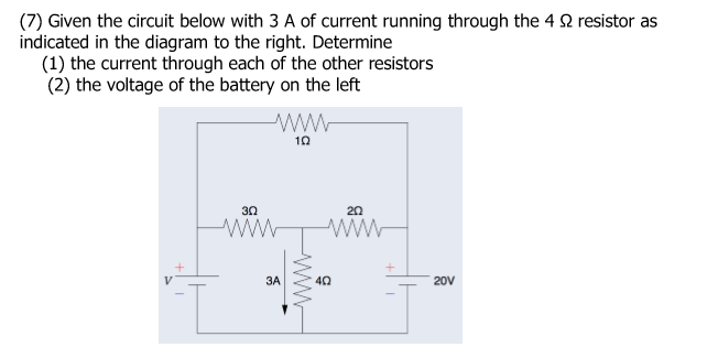
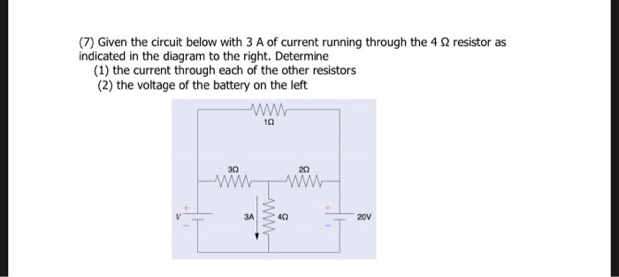
Given the circuit below with 3 A of current running through the 4 Ω resistor as indicated in the diagram to the right. Determine… the current through each of the other resistors; the voltage of the battery on the left; the power delivered to the circuit by the battery on the right

Discontinuous Conduction Mode Left Is More Efficient Than
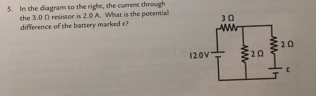
Solved In The Diagram To The Right The Current Through The
State Fleming S Right Hand Rule With A Labelled Diagram

3 The Diagram Below Shows A Circuit With One Battery And 10
Answered Given The Circuit Below With 3 A Of Bartleby

Magnetic Field Due To Current Carrying Circular Loop Ck 12

A Level Siomplified Physic Notesd Docsity
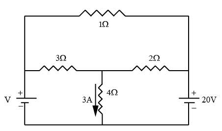
Given The Circuit Below With 3a Of Current Running Through T
Carnegie Institution Of Washington Publication The
Solved You Have Been Asked T0 Calculate Dowei Dissipation By
Solved 8 Given The Circuit Below With 3 A Of Current Chegg Com

For The Circuit Shown In The Diagram Below What Is The Value Of I Current Through 6omega Resis

High Magnetic Fields For Fundamental Physics Cern Document

Blower Motor Resistor For Jeep Grand Cherokee Wh 2005 2007
Top Graph Electric Current And Bottom Graph Heat Current
Psi Physics Electric Current And Circuits Multiple Choice

3 The Diagram Below Shows A Circuit With One Battery And 10

Average Voltage On The Units V Vs Current Through The
Answered 3 21 Using The Diagram To The Right Bartleby

Physics Reference The Diagram Shows Part Of A Current
0 Response to "42 In The Diagram To The Right The Current Through"
Post a Comment