42 Emergency Power Off Switch Wiring Diagram
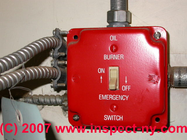
How to Wire A On Off On toggle Switch Diagram. quentacy 19mm 3 4 metal latching pushbutton switch 12v buy quentacy 19mm 3 4" metal latching pushbutton switch 12v power symbol led 1no1nc spdt on off black waterproof toggle switch with wire socket plug blue how to wire a 3 way switch wiring diagram how to wire 3 way light switches with wiring diagrams for different methods of installing the wire. this Switch is intended for disconnecting electrical equipment from its power source quickly and safely, in the case of emergency. any person, even if not familiar with the installation or safety procedures, can shutdown the connected equipment by simply moving the large red lever to the OFF position, clearly indicated on the face of the switch.
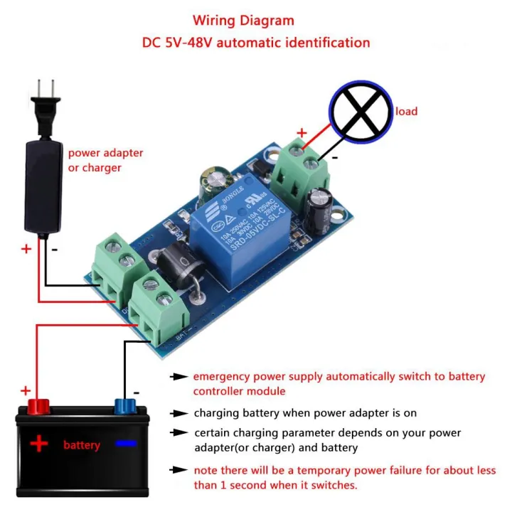
Briggs And Stratton Power Products 071044 01 200 Amp Automatic Transfer Switch W Accm Parts Diagrams. Transfer Switch Manual Panel Wiring Diagram China 208v Auto Switchautomatic Swit Automatic Made In Com. Rlc1 200 Eaton Cutler Hammer 200a Automatic Transfer Switch With Optional Service Disconnect. Ge 100 Amp 240 Volt Non F Emergency Power.

Emergency power off switch wiring diagram
Today i am writing about manual changeover switch wiring diagram, as you know that we use generator as emergency power source in our house wiring , we can do the generator changeover system in two methods, in which one is manual and 2nd one automatic system.This post is about the manual changeover switch wiring diagram for portable generator, and IN SHAA ALLAH we also write and make diagram. Emergency Light Wiring Diagram from lightwiring.co.uk. Print the cabling diagram off and use highlighters in order to trace the routine. When you make use of your finger or even stick to the circuit with your eyes, it's easy to mistrace the circuit. 1 trick that I 2 to print out the same wiring diagram off twice. Typical Wiring Diagrams For Push Button Control Stations 3 Genera/ Information @ Each circuit is illustrated with a control circuit (continued) schematic or line diagram and a control station wiring diagram. l The schematic or line diagram includes all the components of the control circuit and indicates their function.
Emergency power off switch wiring diagram. Today i am writing about manual changeover switch wiring diagram, as you know that we use generator as emergency power source in our house wiring , we can do the generator changeover system in two methods, in which one is manual and 2nd one automatic system.This post is about the manual changeover switch wiring diagram for portable generator, and IN SHAA ALLAH we also write and make diagram. Emergency Light Wiring Diagram from lightwiring.co.uk. Print the cabling diagram off and use highlighters in order to trace the routine. When you make use of your finger or even stick to the circuit with your eyes, it's easy to mistrace the circuit. 1 trick that I 2 to print out the same wiring diagram off twice. Hi Guys, Can you help ? I just wanted to know how you wire a key switch and normal switch together. Is this how it should be :-Feed from board to common on key switch power to emergency lights comes off the load side of key switch loop feed comes off the common side of key switch to common side of normal switch then power to normal lights comes off load side to normal switch. Power circuits feeding shunt-trip breakers are unidentified and unmonitored. Moreover, the systems are rarely documented. There are no shop drawings showing wiring diagrams, location of devices, and intended sequence of operation. Additionally, no maintenance bypass switch is installed that would allow the EPO to be defeated during routine
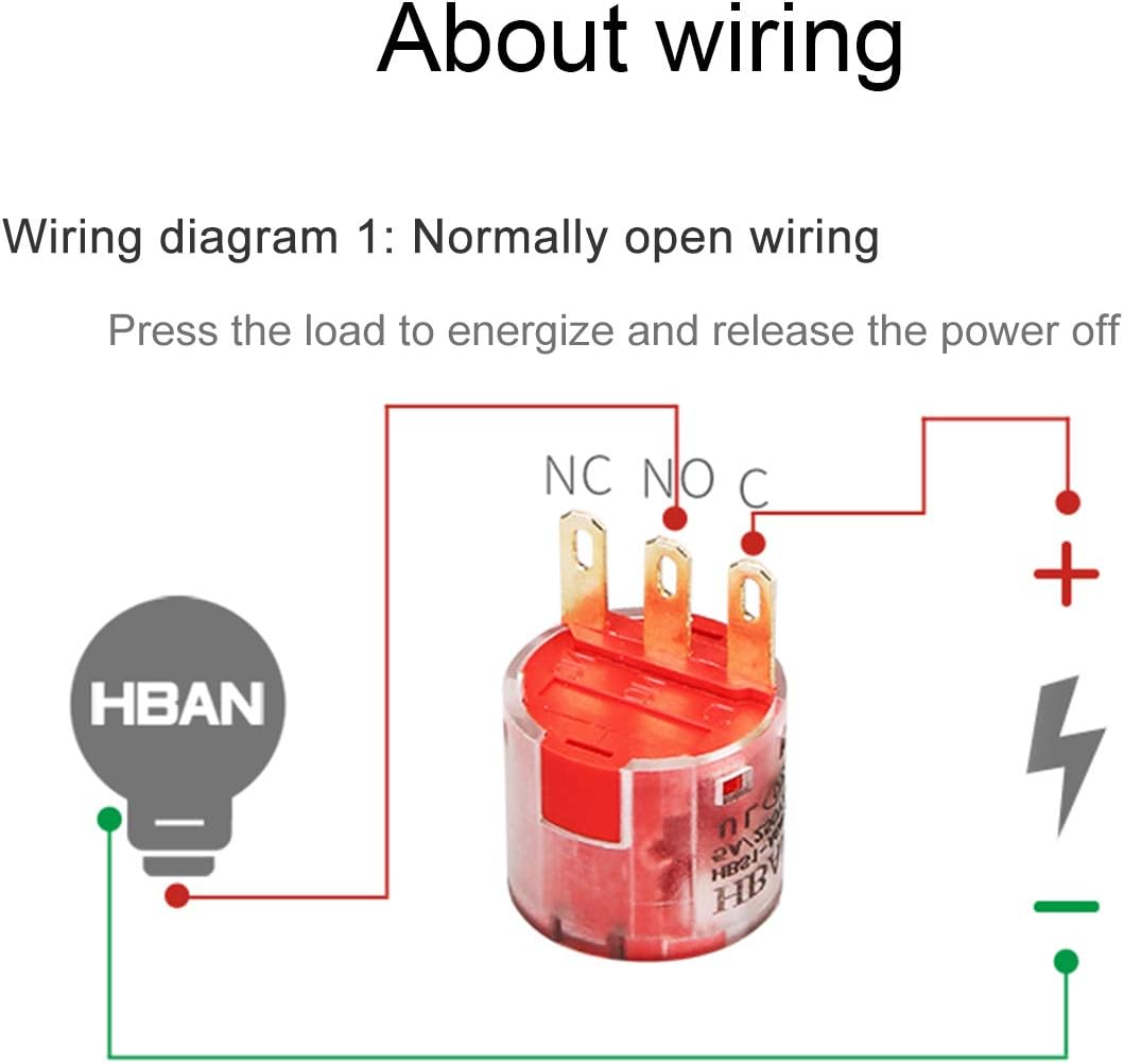
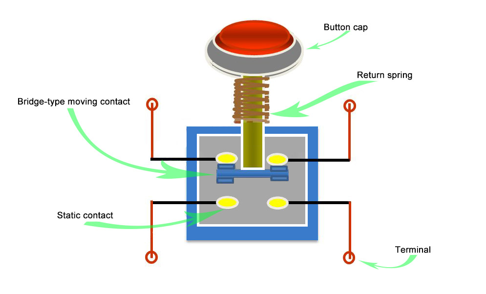
Boiler Emergency Shut Off Switch Wiring Diagram Installation Manual Ny thermal Inc. Boiler Emergency Shut Off Switch Wiring Diagram – wiring diagram is a simplified customary pictorial representation of an electrical circuit. It shows the components of the circuit as simplified shapes, and the capability and signal contacts between the devices. First of all wire your Circuit breaker. Then connect the neutral wire to shunt trip coil. Then connect the Phase (hot wire) to the EPO button normally open contact. Then get connection form EPO other side of normally open contact and connect to the shunt trip coil. Epo Switch Wiring Diagram The Emergency Power-Off (EPO) System consists of one or more wall-mounted, Wiring Diagram... To reset the EPO system: Pull the button toward you. Emergency Power Off (EPO) is the capability to power down a piece of . In the most basic form, the EPO button is wired back to special "remote trip" or "shunt. The GE 100 Amp 240-Volt Non-Fused Emergency Power Transfer Switch is great for running your outdoor backup generator. This emergency power transfer switch is designed for use with 12 - 1 AWG/kcmil copper or aluminum lug wire. With a NEMA type-3R metal enclosure, this transfer switch is UL listed and ANSI certified for safety.
First of all wire your Circuit breaker. Then connect the neutral wire to shunt trip coil. Then connect the Phase (hot wire) to the EPO button normally open contact. Then get connection form EPO other side of normally open contact and connect to the shunt trip coil. Sump pump installation diagram tripwire diagram shunt breaker wiring EPO Switch Wiring DiagramEPO Switch WiringShunt Trip Breaker.Please provide a field wiriing diagram for connecting an EPO in a data center to a Trane Model # XXXXX so that the CRAC unit will shut down when the EPO is engaged.. Remote ‘Emergency Power Off’ switch boxes... Product definition An Emergency Stop is defined as a fail-safe control switch or circuit that, when de-energized, will stop the operation of associated equipment and will shut off all potential hazards outside the main power enclosure. Emergency Stops, or "E-Stops", are a special type of pilot WIRING DIAGRAM for EMERGENCY OPERATION at 120V-277V Emergency Ballast and AC Ballast must be fed from the same circuit Easy Installation & Product Help Tech Help Line Call our experts 888 RAB-1000 ©2012 RAB LIGHTING Inc. Northvale, New Jersey 07647 USA rabweb Visit our website for product info email Answered promptly sales@rabweb PANEL2X4 EM IN-0914
Custer 4 Led Strobe Light Or Running 3 Wire Pigtail Amber Emergency Vehicle Lights Strl4a. On Off Switch Led Rocker Wiring Diagrams Oznium. 10x ámbar 4led Coche Camión Faro De Emergencia Peligro Advertencia Luz Estroboscópica Flash Bar. Wiring Amber White 3 Wire Led Bar Help With Diagram Tacoma World. Nanoflare 12 40w Mini Light Bar.
Single line diagrams of emergency and standby power systems with automatic transfer switch (ATS) (on photo: ATS selects between the normal power grid and emergency generator; credit: interdc.nl) Legal Requirements - As required by the NEC, NFPA 101, NFPA 99 and other local, state, and federal codes and requirements.
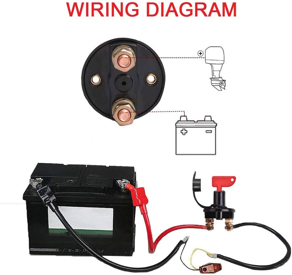
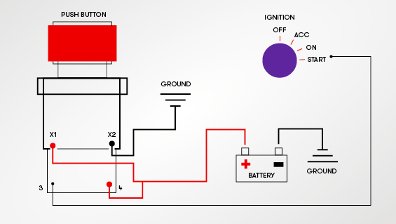
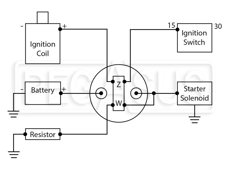
Battery Disconnect Switch Wiring Diagram This battery disconnect is intended to disable the vehicle with an alternator in the event of an emergency. The following diagram is intended for reference only. Due to the many deferent applications and variations of components, it is the responsibility of the installer to verify correct connections.
Fig 4 shows that how to wire a four poles, three phase manual changeover switch to the main distribution board. This is the same connection as we discussed above for single phase wiring expect that there are three phase wires instead of line and neutral. The three phase utility power as (L1, L2, L3 & N) are directly connected to the upper side.
Typical Wiring Diagrams For Push Button Control Stations 3 Genera/ Information @ Each circuit is illustrated with a control circuit (continued) schematic or line diagram and a control station wiring diagram. l The schematic or line diagram includes all the components of the control circuit and indicates their function.
https://ryb .bd/ visit my website http://rybonline / emergency light switch wiring diagram! Switches and Emergency Lighting RYB ELECTRICALবিদেশে.
The idea is to remove power in an emergency, not to control the on/off power of your load. So, this circuit, like the other, will do the job easily also. *Note: I have not bothered to switch the Neutral Line, as we want to remove power to stop a load ie a drill or grinder from running, quickly. This is not a short circuit safety switch.
Emergency Push button Wiring Diagram Download. Assortment of emergency push button wiring diagram. A wiring diagram is a simplified standard photographic depiction of an electrical circuit. It shows the elements of the circuit as streamlined forms, and the power as well as signal connections between the gadgets. A wiring diagram generally gives info regarding the loved…
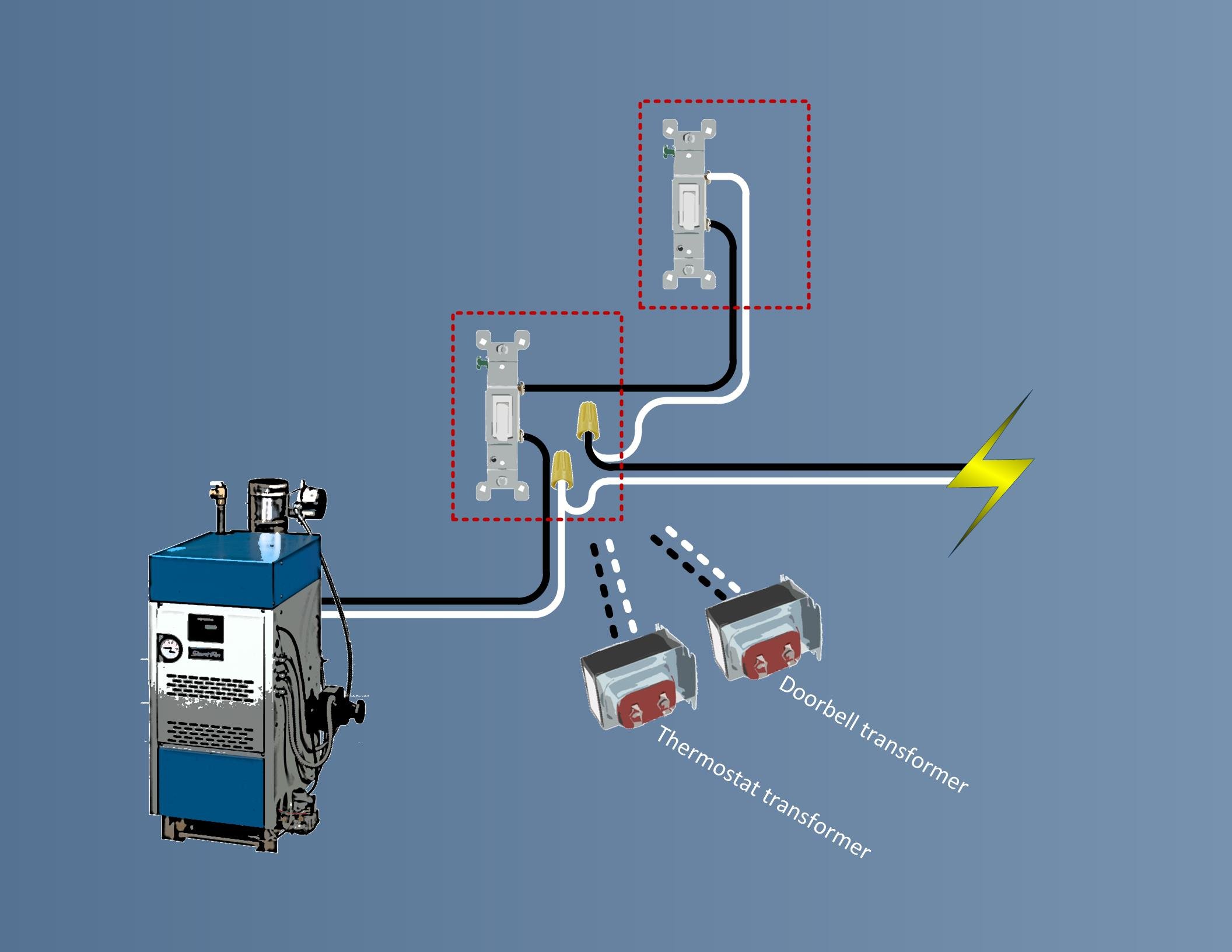
It is fairly common to have two switches to shut a boiler down, One typically at the boiler, the other usually at the top of the stairs or somewhere else. You need a three way switch so that either switch can function (on and Off) independent of the other. Your wiring diagrams are correct. Good job.
Boiler Emergency Shut Off Switch Wiring Diagram wiring diagram is a simplified customary pictorial representation of an electrical circuit. Wiring diagram for float type switch with sensor module. Shop Vac Switch Wiring Diagram Database. This Livewell rocker switch is a Single Pole Single Throw ON-OFF switch.
Emergency Power-Off Circuits Application Note - AN-16 App Note AN -16 Rev. 2.0 1 1995 and 1999 TEAL Electronics Corporation The Emergency Power Off (EPO) button is a common feature in many medical, industrial, and data processing facilities. EPO circuits provide a fast, simple method of shutting down power to a room or piece of equipment.
The Emergency Power-Off EPO System consists of one or more wall-mounted Wiring Diagram. Even though the equipment room EPO switch disconnects main AC power to the equipment room it cannot disconnect the battery power from the J58890CH.
Author's Comment: Generators, associated wiring, and equipment must be installed in accordance with the following. conductor from the normal power to the transfer switch, and the neutral conductor from the generator to the transfer switch, are... or normally off lighting equipment from an emergency supply in the
Emergency Key Switch Wiring Diagram – wiring diagram is a simplified agreeable pictorial representation of an electrical circuit. It shows the components of the circuit as simplified shapes, and the capacity and signal links together with the devices. A wiring diagram usually gives suggestion virtually the relative perspective and covenant of.
















0 Response to "42 Emergency Power Off Switch Wiring Diagram"
Post a Comment