42 A Design Class Diagram Is Also Called A Data Model.
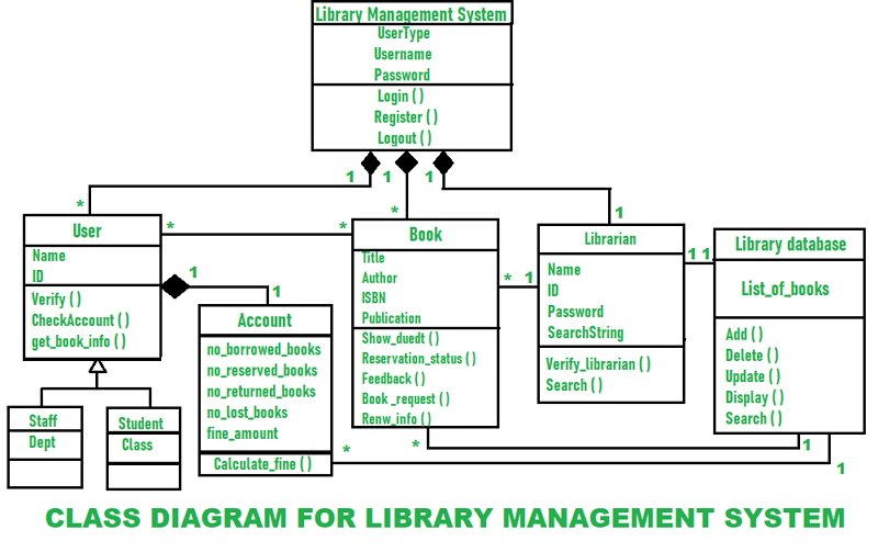
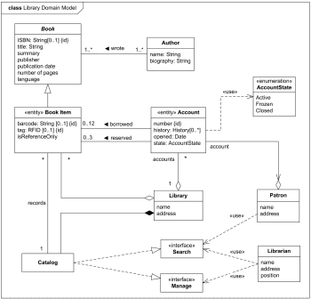
Design a Library Management System. A Library Management System is a software built to handle the primary housekeeping functions of a library. Libraries rely on library management systems to manage asset collections as well as relationships with their members. Library management systems help libraries keep track of the books and their checkouts. Perspectives of Class Diagram. The choice of perspective depends on how far along you are in the development process. During the formulation of a domain model, for example, you would seldom move past the conceptual perspective.Analysis models will typically feature a mix of conceptual and specification perspectives.Design model development will typically start with heavy emphasis on the.
Another name for the data model is the domain model. True. The objective of design activities is to describe in detail the components of the final solution system that will serve as a blue print for construction.. A design class diagram is also called a data model. False.

A design class diagram is also called a data model.
Ishikawa diagrams (also called fishbone diagrams, herringbone diagrams, cause-and-effect diagrams, or Fishikawa) are casual diagrams created by Kaoru Ishikawa (1965) that show the causes of a specific event. Common uses of the Ishikawa diagram are product design and quality defect prevention, to identify potential factors causing an overall effect. A class diagram is a UML diagram type that describes a system by visualizing the different types of objects within a system and the kinds of static relationships that exist among them. It also illustrates the operations and attributes of the classes. They are usually used to explore domain concepts, understand software requirements and describe. Whats the difference between Domain Model Diagram and Design Class Diagram?. _____ is a qualitative measure of how closely the classes in a design class diagram are linked together.. The technique of applying exclusive control to a part of the database to one user at a time is called a(n) _____ _____.
A design class diagram is also called a data model.. Class diagram pros/cons • Class diagrams are great for: - discovering related data and attributes - getting a quick picture of the important entities in a system - seeing whether you have too few/many classes - seeing whether the relationships between objects are too complex, too many in number, simple enough, etc. A class diagram is a UML type static structure diagram that describes the structure of a system by showing the system's classes, their attributes and relationships among objects while ERD is a visual representation of data based on the ER model that describes how entities are related to each other in the database. Ishikawa diagrams (also called fishbone diagrams, herringbone diagrams, cause-and-effect diagrams, or Fishikawa) are casual diagrams created by Kaoru Ishikawa (1965) that show the causes of a specific event. Common uses of the Ishikawa diagram are product design and quality defect prevention, to identify potential factors causing an overall effect. A domain model is called conceptual model in database modeling, while a design model is called logical model. (platform-specific) implementation models , which may be (e.g., JavaScript or Java EE) class models , SQL table models or other types of data models derived from an information design model.
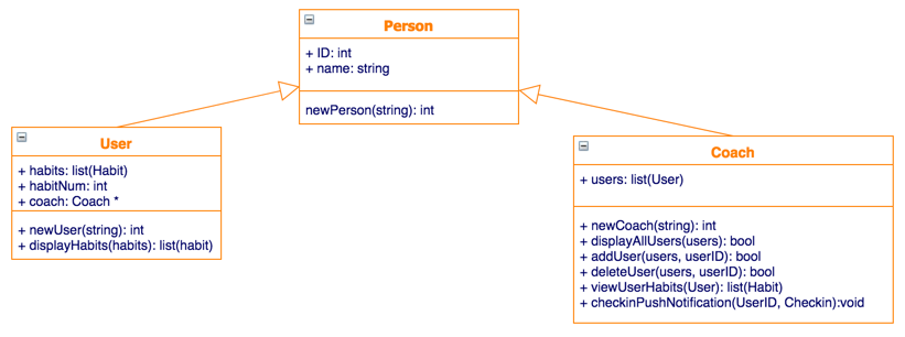
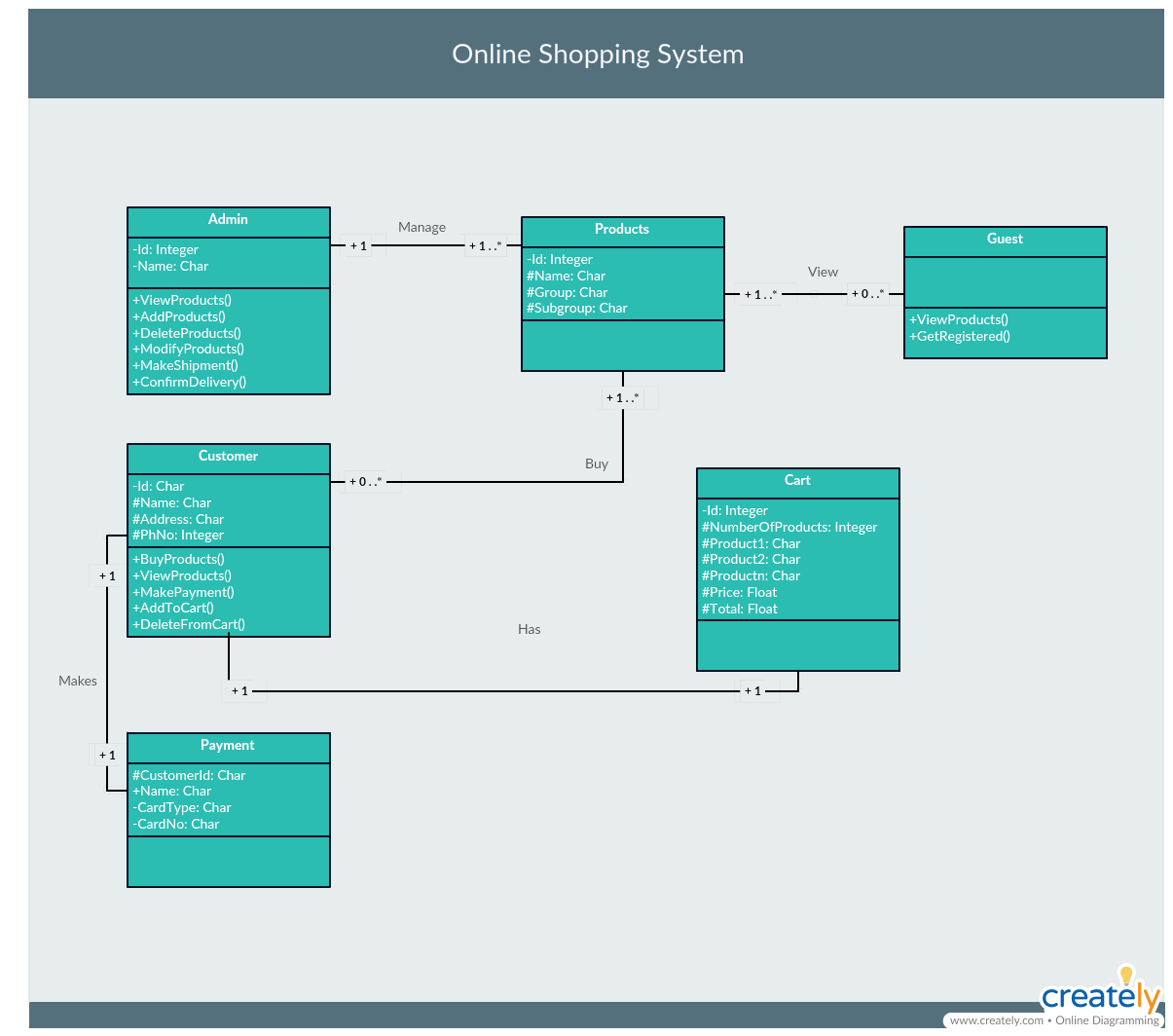
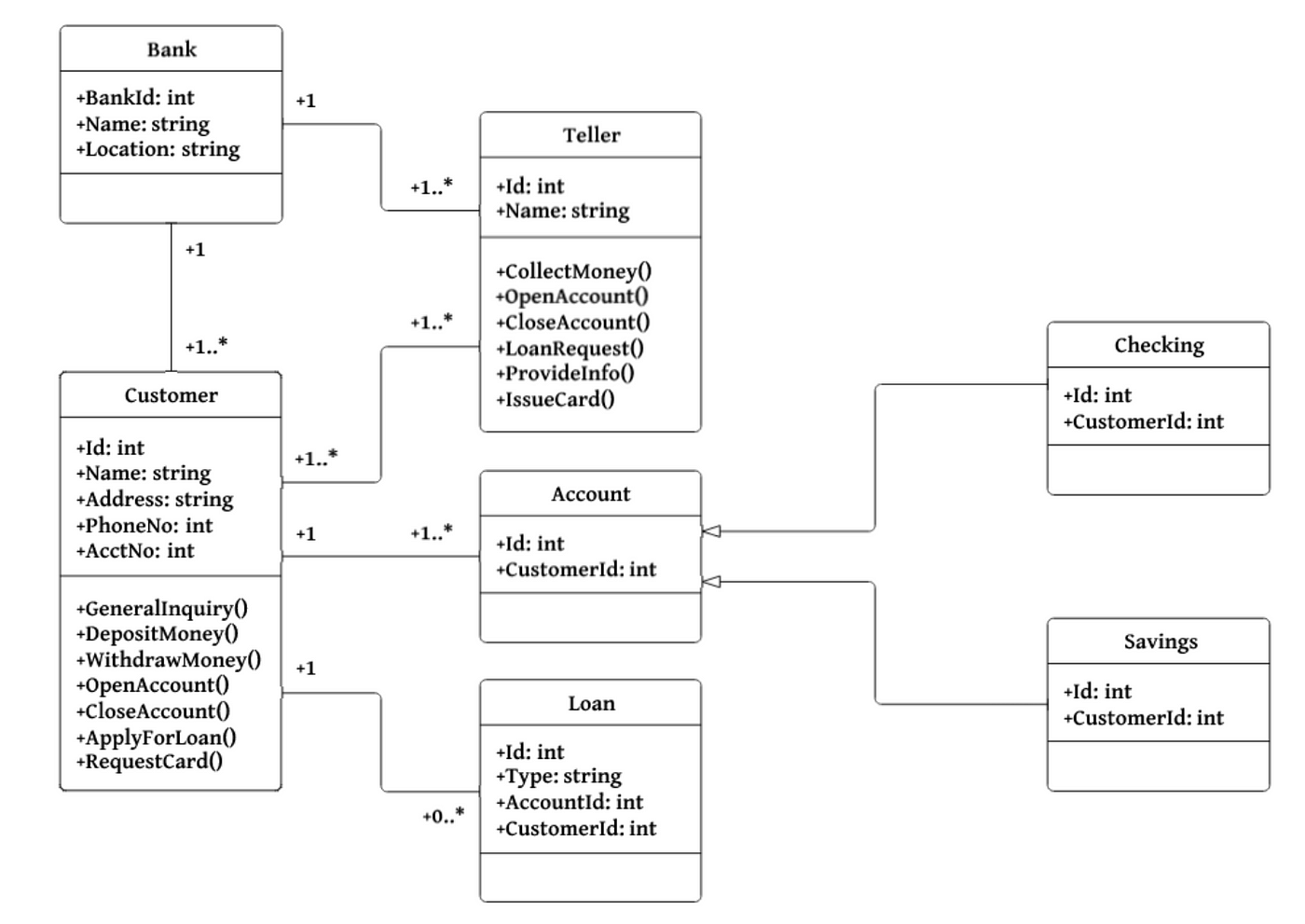
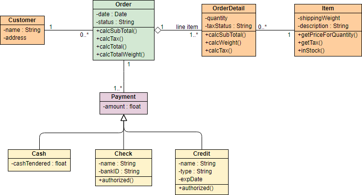
A domain model is called conceptual model in database modeling, while a design model is called logical model. (platform-specific) implementation models, which may be (e.g., JavaScript or Java EE) class models, SQL table models or other types of data models derived from an information design model. Class Diagram Examples. The class diagram example below shows the classes involved in a sales order system. Notice the use of <<enumeration>> class in the class model. The class diagram example below shows a set of classes related to flight management. The classes are grouped under a package. For example, you could use an analysis diagram to understand the domain, a design diagram to show the conceptual solution, and an implementation diagram for the details of the real solution. You can also keep a single model that evolves. But in this case, you'd loose the initial design to keep only the implementation model. Classes are represented by a rectangle on a class diagram. In the simplest format, the rectangle may include only the class name, but may also include the attributes and methods. Attributes are what the class knows about characteristics of the objects, and methods (also called operations) are what the class knows about how to do things.
Another name for the data model is the domain model. True.. A design class diagram is also called a data model. False. Symmetric key encryption uses a public key and a private key. False. An objective of security controls is to maintain a stable operating environment for users. Whats the difference between Domain Model Diagram and Design Class Diagram?. _____ is a qualitative measure of how closely the classes in a design class diagram are linked together.. The technique of applying exclusive control to a part of the database to one user at a time is called a(n) _____ _____. design class diagram. In user interface design the detailed screen layouts should be done after the devices have been decided.. A design class diagram is also called a data model.... The structure of a system is defined by a Class Diagram by showing its attributes, relationships among objects, and so on. It is the backbone of object-oriented modeling and could also be used for Data modeling. Class Diagrams help in making pre-plans which eases the programming process.
UML 2 class diagrams are the mainstay of object-oriented analysis and design. UML 2 class diagrams show the classes of the system, their interrelationships (including inheritance, aggregation, and association), and the operations and attributes of the classes. Class diagrams are used for a wide variety of purposes, including both conceptual.
3 Answers. A domain model is called conceptual model in database modeling, while a design model is called logical model. (platform-specific) implementation models, which may be (e.g., JavaScript or Java EE) class models, SQL table models or other types of data models derived from an information design model. Click to see full answer.
If your focus is on the diagram itself, there are two big differences between diagrams about domain model and diagrams about design model: (At least this is what the Larman book Applying UML and Patterns says). In UML diagrams which represent domain model, you cannot use arrows. All classes are interlinked with a line, which signifies "relation", and you should use text annotations over the.
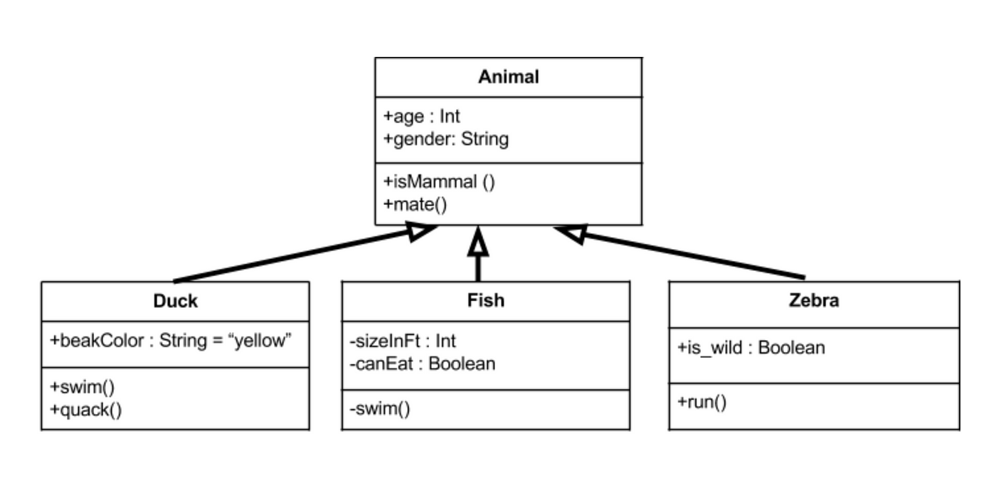
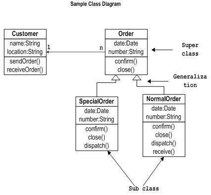
Generalization, Specialization, and Inheritance. Terms such as superclass, subclass, or inheritance come to mind when thinking about the object-oriented approach. These concepts are very important when dealing with object-oriented programming languages such as Java, Smalltalk, or C++. For modeling classes that illustrate technical concepts they.
Note: The diagram you just created is now the active design model. When the Class model is created, the Diagram Window displays a palette with icon symbols used to create class diagrams. The Class Diagram Palette Each icon on this palette represents a notation used to create a class diagram. Some of the objects have related symbols.
The class diagram is the main building block of object-oriented modeling. It is used for general conceptual modeling of the structure of the application, and for detailed modeling, translating the models into programming code. Class diagrams can also be used for data modeling. The classes in a class diagram represent both the main elements.
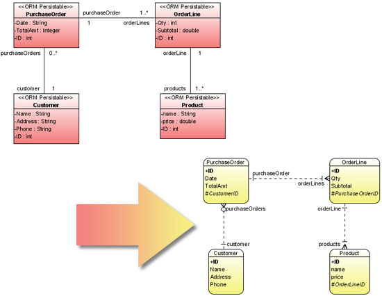
In building a relational database, each class is first translated (mapped) into a relational model scheme. The scheme is identified by the plural form of the class name, and lists all of the attributes in the class diagram. In the relational model, a relation scheme is defined as a set of attributes, together with an assignment rule that.
A design class diagram is also called a data model.. System sequence diagram D)Design class diagram. Free. Multiple Choice. Unlock to view answer. Q 63 Q 63. Software methods are usually identified in which design model? A)Deployment diagram B)State-machine diagram C)System sequence diagram D) Design class diagram.
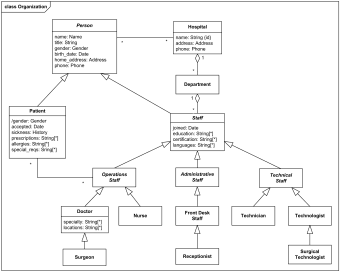
It is also denoted by the Hospital domain Model Diagram. The Domain Model for Hospital Management System is depicted by multiple class diagrams. The diagram gives you a brief idea about the Hospital management process that has small but important substructures such as staff structure, hospital structure, patient treatment terminology, and.
Entity Relationship Diagram, also known as ERD, ER Diagram or ER model, is a type of structural diagram for use in database design. An ERD contains different symbols and connectors that visualize two important information: The major entities within the system scope, and the inter-relationships among these entities.
A domain model is called conceptual model in database modeling, while a design model is called logical model.. These distinctions are also used in model-driven development, where we have a succession of three types of models: (solution-independent) domain models resulting from domain/requirements engineering in the system analysis, or inception, phase of a development project;
A design class diagram is also called a data model. Correct Answer: Explore answers and other related questions 10+ million students use Quizplus to study and prepare for their quizzes and exams through 20m+ questions in 300k quizzes.
A class diagram is a UML diagram type that describes a system by visualizing the different types of objects within a system and the kinds of static relationships that exist among them. It also illustrates the operations and attributes of the classes. They are usually used to explore domain concepts, understand software requirements and describe.
Requirement: A Student can take many Courses and many Students can be enrolled in one Course. In the example below, the class diagram (on the left), describes the statement of the requirement above for the static model while the object diagram (on the right) shows the snapshot (an instance of the class diagram) of the course enrollment for the courses Software Engineering and Database.
A design class diagram is also called a data model. False During analysis, analysts build models to represent the real world and to understand the desired business processes with the information used in those processes.
Generally data models define how the database is implemented. Those diagrams are entity diagrams. A class model is the functional relationships between objects in your system. A class has data but it isn't the data model. A design has both a class model and a data model. As a simple example, a data model exists for a customer.
Hierarchical database model. An oldie but a goodie, this model's data is organized in a tree-like structure. The tree is made up of several groups called segments. It uses a one-to-many relationship. The data access is also predictable. Network model. This model takes the form of a graph, where relationship types are arcs, and object types.
Design class diagrams and interaction diagrams should be developed independent of each other. False. The objective of object-oriented analysis is to identify the objects that must work together to carry out each case.. A design class diagram is also called a data model. False. The Internet can be thought of as the network of networks.
PLAY. An integrity control that verifies the data in one field against the data in other fields is called a ____ control. field combination. Completeness control is an integrity control that identifies when a value in a field is too large or too small. Nice work!
















0 Response to "42 A Design Class Diagram Is Also Called A Data Model."
Post a Comment