42 Autometer Air Fuel Gauge Wiring Diagram
Link engine management and all new electrical wiring Old mechanical rotor ignition changed to coil pack / EMS / digital ignition with new TDC measuring Flex fuel for 85 ethanol to 98 gas--all mixtures go Head with 48 mm intake valves Comet 3 layer head gasket (LR) 140# valve springs (LR) 5 angle seat grind You may use 18g or 20g stranded wire for all fuel level gauge wiring. S = This connects to the sending unit in the fuel tank. **(See Sending Unit Wiring Section) I = Supply 12v, key on power to this terminal. It is recommended to use a 3 Amp automotive fuse when supplying power to this. Therefore Auto Meter offers gauges in many resistance...
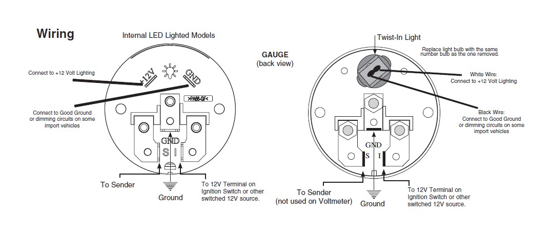
Fuel Level. 1. Gauge connects to fuel sender on fuel tank. Existing wires may be used, or route proper length of 18 gage, wire from fuel tank to gauge. If a new hole is drilled in the firewall a grommet is recommended. Connect one end to terminal post on fuel level sender and the opposite end to the sender (S) terminal spade on back of gauge. 2.
Autometer air fuel gauge wiring diagram
A no-start situation may result from a smart ECU not sensing coil current as a result not energizing the Fuel pump. The 8912 tach adapter will develop an artificial coil current to sadisfy the Smart ECU’s requirement to energize the Fuel pump again. An erratic tach or non working tach is a result of the factory wire being removed from the coil -. Voltage gauge installation instructions how to install auto meter voltmeter electrical jeep logo on your 87 18 wrangler yj tj jk jl extremeterrain 3 ways a car volt amp wikihow troubleshooting boat gauges instrumenteters boatus wire electric proper operation stangnet for cobalt air fuel ratio digital 79 17 all americanmuscle wiring diagram png 1200x1200px ammeter ampere direct cur… Read More » The Auto Meter Air/Fuel gauge has a signal output for supplying information to a Data Logger or engine management system. The signal provided is a linear 0-4 volts output. 0 volts out equals 10.0 Air/Fuel Ratio, 4 volts out equals 18.0 Air/Fuel Ratio. Note: Due to the limitations of the sensor, the indicated Air/Fuel Ratio
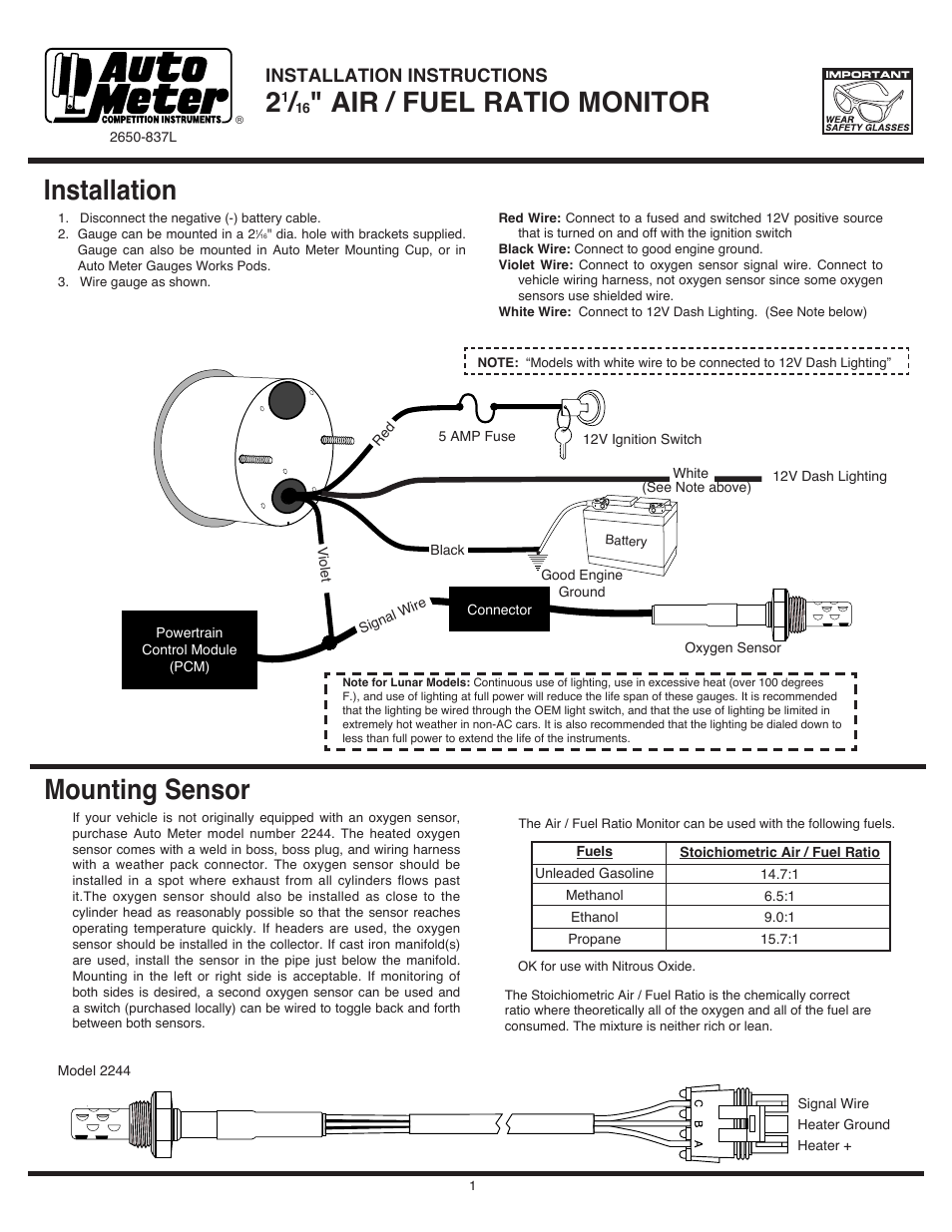
Autometer air fuel gauge wiring diagram. Wiring Diagram For Car Voltmeter. Vdo gauge wiring diagram voltage full how to install auto meter voltmeter volt the hull truth boating mad with autometer cobalt air fuel ratio 3 ways a car amp installation instructions direct fit dash panel short sweep electric gauges dimmer switch monitor oil pressure an ford ranger tachometer 2 1 16 8 18v core electrical network for ammeter vintage wires. Autometer Boost Gauge Wiring Diagram. How to Install an Auto Meter Pro-Comp Ultra-Lite Air/Fuel Ratio Gauge - Electric on Your M or wiring diagram for your specific vehicle to learn which wire is the signal. WARNING. Do not connect ohm meter to oxygen sensor, or touch wire to ground or power. Damage to oxygen sensor will result. diagramweb . Kenworth rpm gauge not working 16" WIDE BAND AIR/fUEL RATIO mONITOR ® 2650-1143-00 Rev. A Installation 1. Disconnect the negative (-) battery cable. 2. Gauge can be mounted in a 21⁄ 16" dia. hole with brackets supplied. Gauge can also be mounted in Auto Meter Mounting Cup, or in Auto Meter Gauge Works Pods. 3. Wire gauge as shown. 12V Ignition Switch Good Engine Ground
Fuel gauge wiring. In my '65 Fastback the fuel wire splits off from the bundle containing the taillight and brake light Standard Resistive Gauges 52mm 12/24 Volt (2011) Standard Resistive Gauges 52mm 12/24 Volt Retrofit Kit (Temperature, Pressure, Level, Trim) (2013) Temperature Resistance Chart (2004) VDO Cylinder Head Temperature Gauge Handlebar/Fairing Mount - 2009. Trans Temp Gauge Installation: but an A-pillar gauge mount is available as a professional location to mount two gauges. diagramweb has a 2 & 3 gauge pod available Pictured below is a copy of the wiring diagram for the Autometer Transmission Temperature Gauge. STEP 4. Fuel Level Gauges Autometer How They Work How To Install Tutorial Instructions Ohms Wiringhttp://www.jegs /vct/Auto+Meter/105/1010331-----... Auto Meter Volt Gauge Wiring Diagram Images Nomor Siapa. Autometer volt gauge wiring cheap auto meter gauges diagram full transmission temperature temp cobalt air fuel ratio how to install direct fit monitor installation oil pressure 4337 ultra lite 2 1 16 100 help electric 6537 digital 4375 user manual 4 pages sea water problems with inch 52mm car red led 250 f instructions كواجا مرة.
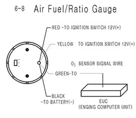
Re: How to install autometer air/fuel gauge. Middle wire on the o2 sensor plug is the signal wire you need to tap in to. If you have a red top, with the skinny o2 (stock red top o2) it WILL NOT WORK. if you get a fat o2, the gauge will work but the #62 and #63 ecus don't read fat o2 sensors. Gauge can be mounted in a 21⁄16" dia. hole with brackets supplied. Gauge can also be mounted in Auto Meter Mounting Cup, or in Auto Meter Gauges Works Pods. Wire gauge as shown. Red Wire: Connect to a fused and switched 12V positive source that is turned on and off with the ignition switch. Black Wire: Connect to good engine ground. I chose to ground mine to a chassis bolt located just inside the fuse box. And the 12 volt switched circuit for my trans temp gauge. (Click to enlarge) Fuse Box (Click to enlarge) Ground Location: Pictured below is a copy of the wiring diagram for the Autometer Air/Fuel Ratio Gauge: Questions? Email me & ask Autometer Air Fuel Ratio Gauge Wiring Diagram. Autometer Fuel Pressure Gauge Wiring Diagram. Autometer Water Temp Gauge Wiring Diagram. Mercury Outboard Trim Gauge Wiring Diagram. Autometer Electric Fuel Pressure Gauge Wiring Diagram. One Line Diagram Symbols. 59 Cummins Fuel Line Diagram.
Autometer Gauge Wiring Diagram - auto meter gas gauge wiring diagram, autometer amp gauge wiring diagram, autometer boost gauge wiring diagram, Every electric structure consists of various unique pieces. Each part should be placed and linked to other parts in specific manner. Otherwise, the structure won't work as it should be.
Over the years, Auto Meter has established itself as a manufacturer of quality, professional automotive gauges. Adding any Auto Meter gauge to your vehicle will help to ensure accurate and consistent readings from your car or truck. Installing an Auto Meter fuel gauge is an easy task once you have decided how and.
Digital, electrical, or mechanical and in five sizes, these professional-quality, aluminum race gauges weigh half as much as typical units. Silver satin anod...
Voltage gauge installation instructions how to install auto meter voltmeter electrical jeep logo on your 87 18 wrangler yj tj jk jl extremeterrain 3 ways a car volt amp wikihow troubleshooting boat gauges instrumenteters boatus wire electric proper operation stangnet for cobalt air fuel ratio digital 79 17 all americanmuscle wiring diagram png 1200x1200px ammeter ampere direct cur… Read More »
Nov 15, 2021 · Tail Light Wiring Diagram 98 Sierra Wiring Diagram Data Schema. Speartech Fuel Injection Systems. com/241430h. LS Swap cost: 50 motor tranny motor mounts: 0 computer wiring redo: 0 Fuel system: 0 Headers: 0 Exhaust redo: 0 Shifter: 0 Air conditioning redo: 0 - 00 Driveshaft 0 total: ,880 - ,880 just for required changes to get back to where you.
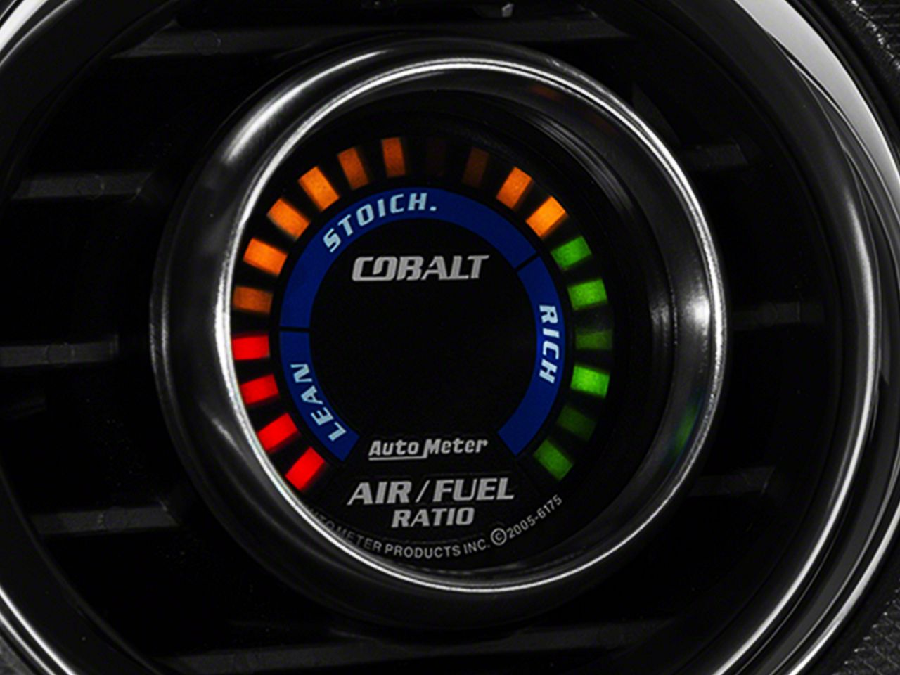
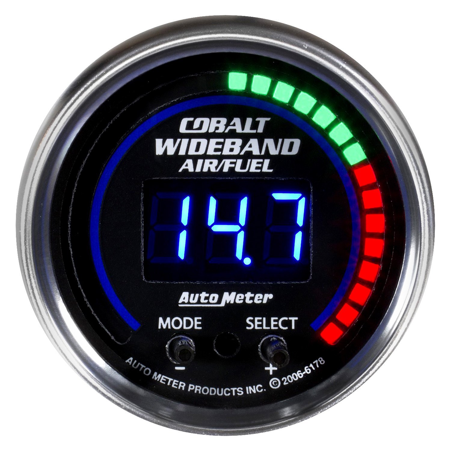
Auto Meter Cobalt Wideband Air/Fuel Ratio Gauge - Analog ( All) I found that the factory Oxygen sensor wiring was a secure location to. Gauge can also be mounted in Auto Meter Mounting Cup, or in Auto Meter Check with vehicle manufacturer or wiring diagram for your specific vehicle to learn. Shop schematron for Autometer oil pressure gauges.
Autometer Fuel Level Gauge Wiring Diagram – wiring diagram is a simplified all right pictorial representation of an electrical circuit. It shows the components of the circuit as simplified shapes, and the capability and signal friends between the devices. A wiring diagram usually gives guidance practically the relative incline and treaty of.
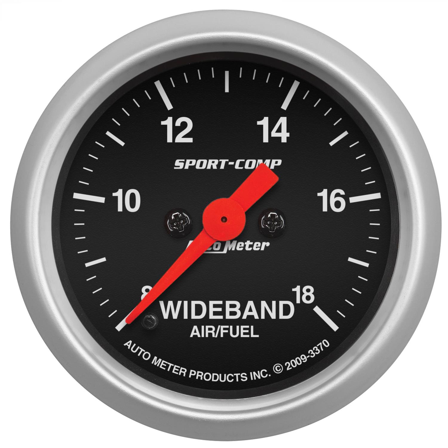
4379 Gauge, Air/Fuel Ratio-Wideband, Street, 2 1/16", 10:1-17:1, Digital,. and it compliments my factory Mazdaspeed Miata gauges well. I mounted it in my glove box with an Autometer boost gauge , and will be adding water temp, and oil pressure.... Could you please send me wiring diagram. I have tried even hooking the brown wire to the ...
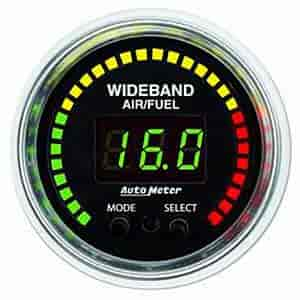
Air Fuel Ratio Gauges & Kits Here at AutoMeter, we offer a wide selection of industry-leading Air Fuel ratio gauges to keep your vehicle from running too rich or too lean. With our vast assortment of both narrow band and wideband air fuel gauges to monitor your motor, avoiding expensive repairs has never been easier.
An air fuel gauge can be connected much easier than you might think. It might seem like quite a task at first, but installing and mounting an air fuel gauge in your vehicle is something you can do yourself in a short amount of time. An air fuel gauge will allow you to monitor the changes in oxygen content in the air.
Autometer Air Fuel Gauge Wiring Diagram Rate Fuel Gauge Wiring – Autometer Gauge Wiring Diagram. Additionally, Wiring Diagram provides you with enough time frame by which the assignments are to be accomplished. You will be able to learn exactly once the projects should be completed, that makes it easier for you to correctly manage your time.
Digital Air/Fuel Ratio Gauge User Manual Warning!. 2.1 Wiring The MTX-L has 5 stripped wire ends: 1 Connect the RED wire to an isolated switched 12V source in your... See the next section for a relay installation diagram. 2 The BLACK wire should be grounded to a solid ground source. The
2 1 16 Fuel Pressure 0 100 Psi Stepper Motor Phantom. Diagram Auto Gauge Wiring Oil Temp Full Version Hd Quality. 2 1 16 Narrowband Air Fuel Ratio Lean Rich Phantom. Start Kart Plans. Air Fuel Ratio Gauge. Boost Gauge Png Images Pngwing. Auto Meter 3810 User Manual 2 Pages Also For 5910 8010 1109.
18 gage, wire from fuel tank to gauge. If a new hole is drilled in the firewall a grommet is recommended. Connect one end to terminal post on fuel level sender and the opposite end to the sender (S) terminal spade on back of gauge. 2. Connect ground wire from ground post on gauge to suitable chassis ground. 3.
Autometer Gas Gauge Wiring Diagram. Diagram auto meter phantom gauge wiring mogar infinityagespa it installation instructions for cobalt air fuel ratio digital 79 17 all americanmuscle how to test and replace your sending unit sail magazine 3810 user manual 2 pages also 5910 8010 1109 21 16 quot monitor automotive rcolor 1 level 0 90 Ω core gm.
Autometer Phantom Fuel Gauge Wiring Diagram have a graphic from the other. Autometer Phantom Fuel Gauge Wiring Diagram It also will include a picture of a kind that may be observed in the gallery of Autometer Phantom Fuel Gauge Wiring Diagram. The collection that comprising chosen picture and the best amongst others.
Autometer Air Fuel Gauge Wiring Diagram Rate Fuel Gauge Wiring - Autometer Gauge Wiring Diagram. Additionally, Wiring Diagram provides you with enough time frame by which the assignments are to be accomplished. You will be able to learn exactly once the projects should be completed, that makes it easier for you to correctly manage your time.
2. Gauge can be mounted in a 21 ⁄16" dia. hole with brackets supplied. Gauge can also be mounted in Auto Meter Mounting Cup, or in Auto Meter Gauge Works Pods. 3. Wire gauge as shown. Red Wire: Connect to a fused and switched 12V positive source that is turned on and off with the ignition switch. Black Wire: Connect to good engine ground.
A no-start situation may result from a smart ECU not sensing coil current as a result not energizing the Fuel pump. The 8912 tach adapter will develop an artificial coil current to sadisfy the Smart ECU’s requirement to energize the Fuel pump again. An erratic tach or non working tach is a result of the factory wire being removed from the coil -.
Peterbilt Speedometer Wiring Diagram - Warn Winches Schematic - 1990-300zx. Add to cart. t. 2011 · 1998 379 peterbilt speedometer and odometer quit. Joined: Apr 5, 2014 Messages: 19 Location: New This is a repair service for a 2006 Peterbilt.
Auto Meter Products. 413 W Elm St. Sycamore, IL 60178. Toll Free Tech Support: 866.248.6357. Toll Free Customer Service: 866.248.6356. International: 815.895.8141
Dynoracing 2 52mm 7 Colors Led Car Air Fuel Ratio Gauge Narrowband Air Fuel Ratio Meter With High Speed Motor Bx101493
Autometer Electric Fuel Pressure Gauge Wiring Diagram. Learn More and Buy Direct Here. Ad Bring Out the Best Performance with the Most Accurate and Durable Gauges for Any Upgrade. 18 gage wire from fuel tank to gauge. Pictured below is a copy of the wiring diagram for the Autometer Oil Pressure Gauge. Universal gauge wire harness for installing.
The Auto Meter Air/Fuel gauge has a signal output for supplying information to a Data Logger or engine management system. The signal provided is a linear 0-4 volts output. 0 volts out equals 10.0 Air/Fuel Ratio, 4 volts out equals 18.0 Air/Fuel Ratio. Note: Due to the limitations of the sensor, the indicated Air/Fuel Ratio
Analog Wideband Air/Fuel Ratio Gauge Figure 1. Wiring Schematic AEM Gauge-Type UEGO Controller Parts 1 x 35-5130(B/W) UEGO Gauge Assembly 1 x 30-2001 UEGO Sensor 1 x 35-8535 Install Kit (O2 Bung with 6 Butt Connectors) 1 x 10-5130 Installation Instructions 1 x 35-3411 8-Pin Power Harness
May 19, 2010 · 7.3L Wiring Schematic Printable, very handy. Handy Wiring Diagram that shows a Paper Trail of how the Electrical System Works for the 7.3L Powerstroke Engines, all Trucks, Excursions, Vans. It was a Copy I had to PhotoShop to make it Readable & Printable. it's very detailed and shows how every wire for each component routes to the PCM.














0 Response to "42 Autometer Air Fuel Gauge Wiring Diagram"
Post a Comment