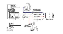
41 Pod Brake Controller Wiring Diagram
737 400 Air Conditioning System Schematic Diagram. Accu Power Pod Brake Controller . Acdelco 15926102 Gm Original Equipment Trailer Brake Control Switch Assembly . Reese Pod Wiring Diagram Wiring Diagram . Endless Brake Pads Set Circuit Compound Cc35 Type E N84m Alcon Ap Racing Caliper Cp6060 6065 6075 6080 Rcp072 Instructions for Pod® Brake Control READ THIS FIRST: Read and follow all instructions carefully before installing or operating the Brake Control. Keep these instructions with the Brake Control for future reference. D B C A Installation Guide A. Mounting Bracket B. #6 x 3/8" Screws C. Mounting Holes A C B P/N 7760 REV G NOTE: 1.
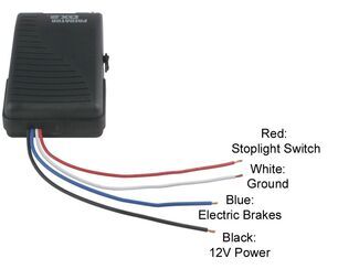
Verify that the white brake controller wire (ground function) is connected to the negative battery terminal. Verify that the black brake controller wire (12V power function) is connected to the positive battery terminal with a 20 or 30 amp circuit breaker installed in line. For trailers with 2-4 brakes, use a 20 amp breaker and for trailers with 6-8 brakes, use a 30 amp breaker.

Pod brake controller wiring diagram
Add both to Cart. Choose items to buy together. This item: Tekonsha 80500 Pro Series POD Brake Control. $36.30. In Stock. Ships from and sold by Amazon . FREE Shipping. Tekonsha 3035-P Brake Control Wiring Adapter for Ford. $12.20. The brake control must be installed with a 12 volt negative ground system. (To install with a positive ground system use Tekonsha ® P/N 3191.) 2. WARNING Reversing BLACK and WHITE wires or improper wiring will damage or destroy brake control. 3. WARNING Be sure to solidly connect all four wires or brake control will not function properly. 4. Place the pod controller inside the cab of the vehicle near its. Hayman reese electric brake controller wiring diagram wiring diagram is a simplified tolerable pictorial representation of an electrical circuit it shows the components of the circuit as simplified shapes and the capacity and signal contacts between the devices.
Pod brake controller wiring diagram. POD Brake Control for 1 & 2 Axle Trailers - #80500. Features Include: Solid State Electronics. Power-on LED Light for a positive tow vehicle to trailer connection. Has a manual over-ride control. Very rugged, and has a easy mount chassis. All Mounting Hardware is included. Step 1. Connect the supplied pigtail wiring harness into the electrical connection port on the rear of the pod brake controller. Purchase a wiring harness specific to your vehicle application from your vehicle's manufacturer, and plug that harness into the recommended connection portal. Place the pod controller inside the cab of the vehicle. The brake control must be installed with a 12 volt negative ground system. (To install with a positive ground system use Tekonsha ® P/N 3191.) 2. WARNING Reversing BLACK and WHITE wires or improper wiring will damage or destroy brake control. 3. WARNING Be sure to solidly connect all four wires or brake control will not function properly. 4. Accu Power Pod Brake Control Pro Series 80550. Hayes brake controller wiring diagram trailer control troubleshooting 80500 accu power pod full reese towpower controllers 7437711 find electronic timed controls installation starting the best and pro series 16 f250 f350 f450 f550 new x4 lot reviews of 2021 14 18 silverado sierra 7 for rvs 550 oem page 3 towing 74 vw alternator 95 09 dodge 83501.
Add both to Cart. Choose items to buy together. This item: Tekonsha 80500 Pro Series POD Brake Control. $36.30. In Stock. Ships from and sold by Amazon . FREE Shipping. Tekonsha 3035-P Brake Control Wiring Adapter for Ford. $12.20. Reese Pod Brake Controller Wiring Diagram. Effectively read a wiring diagram, one provides to find out how the particular components inside the program operate. For example , if a module will be powered up and it also sends out the signal of half the voltage and the technician will not know this, he would think he has a problem, as this. Wiring Diagram Reese Pod Brake Controller Wiring Diagram. Motors Wiring Wiring Diagram 1 Ohm Subwoofer Wiring Diagram. Wiring Diagram Wiring 2 Lights With 2 Switches. Leave a Reply Cancel reply. Your email address will not be published. Required fields are marked * Comment. Name * Email * Website. Draw-Tite Activator Electronic Brake Control 1-2 Axle Trailers (2-4 Brake Trailers) $85.00 Activator® IV Electronic Brake Control, for 1 to 4 Axle Trailers, Timed Actuated
Reese Trailer Brake Controller Wiring Diagram - People understand that trailer is a car comprised of very complicated mechanics. This vehicle is designed not only to travel one place to another but also to carry heavy loads. This guide will be discussing reese trailer brake controller wiring diagram.What are the advantages of knowing such understanding? GM Chevy Trailer Brake Controller Install: How to put a trailer brake controller in a 1999 - 2007 GMC / Chevrolet / Cadillac Truck or SUV Suburban! Works in. The brake control must be installed with a 12 volt negative ground system. (To install with a positive ground system use Tekonsha ® P/N 3191.) 2. WARNING Reversing BLACK and WHITE wires or improper wiring will damage or destroy brake control. 3. WARNING Be sure to solidly connect all four wires or brake control will not function properly. 4. R Pod Trailer Wiring Diagram – People today comprehend that trailer is a vehicle comprised of very complicated mechanisms. This automobile is designed not just to travel 1 location to another but also to carry heavy loads. This guide will be talking r pod trailer wiring diagram.What are the benefits of understanding such understanding?
Place the pod controller inside the cab of the vehicle near its. Hayman reese electric brake controller wiring diagram wiring diagram is a simplified tolerable pictorial representation of an electrical circuit it shows the components of the circuit as simplified shapes and the capacity and signal contacts between the devices.
1. Connect the supplied pigtail wiring harness into the electrical connection port on the rear of the pod brake controller. Purchase a wiring harness specific to your vehicle application from your vehicle's manufacturer, and plug that harness into the recommended connection portal. Reese has always strived to provide the right trailer towing.
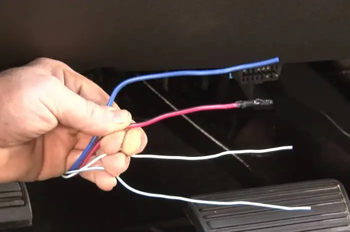
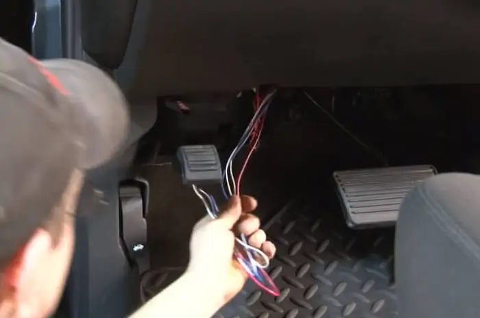
SUBJECT / Summary: Wiring electric brake controls on 2007-2013 GM full size trucks and 2007-present GM SUVs including Cadillac Escalade, Chevy Silverado (new body) Chevy Suburban, Chevy Tahoe, GMC Sierra (new body) and GMC Yukon. PROBLEM: General Motors quit offering the plug in type connectors on these vehicles with a factory tow package. These models have four (possibly five) blunt cut wires.
The Reese Towpower Pod Brake control is your best choice for one or two axle trailer, especially when your installation options are limited. The controller features solid state electronics, power-on LED for a positive tow vehicle-to-trailer connection and up-front manual over-ride controls.
Reese Pod Brake Controller Wiring Diagram from images-na.ssl-images-amazon Effectively read a wiring diagram, one provides to find out how the components inside the program operate. For example , when a module is usually powered up also it sends out a signal of 50 percent the voltage plus the technician would not know this, he'd think he.
Installing a brake controller involves disconnecting the vehicle battery, mounting the brake controller onto dash and plugging the unit in with a vehicle-specific wiring harness. If your vehicle is not equipped with a plug-and-play harness, you can also splice in wiring for connecting a brake controller. In this guide, we cover step-by-step how to install a brake controller.
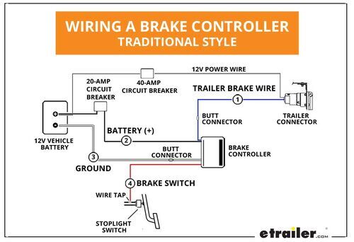
The wiring diagram to the right is a basic brake controller hook up. The wiring harness shown is typical of any electric brake control installation. Some newer vehicles provide their own brake control jumper harness which makes the install a plug and play affair. When you purchase a brake controller and install it on a vehicle without a factory.
Reese pod brake controller wiring diagram; A wiring diagram normally provides details regarding the… Trailer wiring diagrams 4 way systems. Elecbrakes is designed to operate 1 to 2 braked axles; Just 5 steps to install brake controller and wiring! Auxiliary connection is optional, it may be connected to any 12v to 24v constant power source or.
Pod Point are UK leaders in electric vehicle charging with innovative solutions for homes workplaces and commercial organisations. Pod Brake Controller Wiring Diagram Point R 177 Challenger Radio. Guitar POD unit Amplifier CDMP3 input with 14 dummy plug in the instrument input 2 If your amplifier has an effects loop ie.
Electric Brake Controller Wiring Diagram. Wiring Diagram. Auxiliary connection is optional, it may be connected to any 12v to 24v constant power source or left unconnected. Break away systems may be added to the service brake circuit. Elecbrakes is designed to operate 1 to 2 braked axles. Get.
Wiring diagram for reese brake controller. Quick splice connectors and circuit tester included. The 27l i4 standard in all regular and access cab trucks regardless of drive train not available in the x runner or double cab trucks. Additional wire leads for brake power and accessory are 12 long. Tow ready wiring 30717.
Reese pod brake controller wiring diagram 1. Source: wholefoodsonabudget . These wiring diagrams are wrong, red wire is brake light wire not aux power wire (black can be used for that.as it is the aux wire) and the blue wire is electric brake control wire for those larger trailers this article shows 4 ,7 pin trailer wiring diagram connector.
Presented by Hayman Reese technical towing expert Gary Gardiner, watch the typical installation process of Hayman Reese Brake Controllers, including end-to-e...
Reese Pod Brake Controller Wiring Diagram. schematron Today on this Chevrolet Silverado were going to install part number The Pod (Power on Demand) trailer brake control is your best choice, Accu- Power Pod Brake Controller, Tekonsha Installation Instructions, CLICK HERE. The REESE Towpower POD trailer brake control is designed for one to.







0 Response to "41 Pod Brake Controller Wiring Diagram"
Post a Comment