41 Function Generator Circuit Diagram
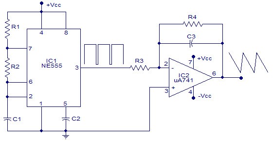
DPDT circuit diagram: Fig 1.2 DPDT Terminal Diagram Look at picture 1.1 and 1.2, it consists of two common input terminals C, E and both mechanically tied together to operate in the same way. Function Generator. Circuit diagram. Built around a single 8038 waveform generator IC, this circuit produces sine, square or triangle waves from 20Hz to 200kHz in four switched ranges. There are both high and low level outputs which may be adjusted with the level control. This project makes a useful addition to any hobbyists workbench as well.
First, a function generator (also called a tone generator) is an electronic device that can output a specific waveform at a set frequency. For example, one could generate a sinusoidal signal at 60Hz. You can use it to test the inner workings of audio amplifiers, find the characteristic of op-amps and diodes, make funky noises—the list of.
Function generator circuit diagram
The XR-2206 is a monolithic function generator integrated circuit capable of producing high quality sine, square, triangle, ramp, and pulse waveforms of high-stability and accuracy. The output waveforms can be both amplitude and frequency modulated by an external voltage. Frequency of operation can be selected Aug 13, 2017 · The block diagram of a function generator is given in the figure. In this instrument, the frequency is controlled by varying the magnitude of the current that drives the integrator. This instrument provides different types of waveforms (such as sinusoidal, triangular and square waves) as its output signal with a frequency range of 0.01 Hz to. The Sweep/Function Generator as developed by L. J. Haskell was designed and built as a. Figure 1 - Circuit diagram schematic of DDS module. Figure 2 - Bottom view of DDS module Figure 3 - Top view of DDS module. First is to bring the RSET pin (12) out to connector. To free up the pin you have to cut the trace
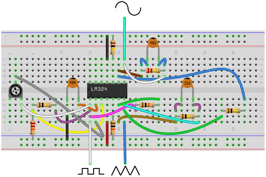
Function generator circuit diagram. Function Generator Circuit Diagram with LM324 Op-Amp The LM324 is a 14-pin integrated circuit, the circuit diagram of the function generator with LM324 is shown below. The components required for this circuit are LM324 op-amp chip, two 10kΩ resistors, four 100kΩ resistors, 22kΩ resistor, 220kΩ resistor, 1μF ceramic capacitor, 33 nF ceramic. Circuit Descriptions Power Supply - DC Regulation The voltage regulators are mounted on a separate pcb. IC10 and IC11 provide ±15V, IC8 and IC9 provide ± 5V. Waveform Generation IC1 is an integrated waveform generator and provides sinewave, squarewave and triangle output. Q1 to Q6 select the range capacitor. Function generator ranging from 0.1 Hz to 20 MHz can be easily built using MAX038 integrated circuit chip. Here is the most simple implementation of high frequency sine wave generator, and you can easily modify it to generate square wave, or triangle waveform. Here is the schematic diagram of the circuit: In the schematic diagram, you can see. Introduction. Function and arbitrary waveform generators are among the most important and versatile pieces of electronic test equipment. In electronic design and troubleshooting, the circuit under scrutiny often requires a controllable signal to simulate its normal operation.
Circuit Diagram is a free application for making electronic circuit diagrams and exporting them as images. Design circuits online in your browser or using the desktop application. The main parts of this project are 1. A square wave generator 2. An integrator which converts square waves to triangular waves. The circuit uses an opamp based square wave generator for producing the square wave and an opamp based integrator for integrating the square wave. The circuit diagram is shown in the figure below. Circuit diagram The complete circuit diagram this Arduino Function Generator is shown below. The block diagram of a function generator is given in the figure. Working of Function generator circuit. The 1458 is a dual. This is a simple function generator circuit that can produce the following waveforms. Build the Function Generator 1. A circuit diagram is a simplified representation of the components of an electrical circuit using either the images of the distinct parts or standard symbols. A circuit diagram is also known as an electrical diagram, elementary diagram or electronic schematic.
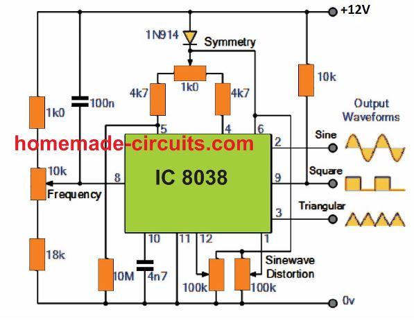
The function generator is an electronic device or circuit used to generate electronic signals with different waveforms and different frequencies. A function generator can generate a sine wave, triangular wave, square wave electronic signals. Also, a function generator can generate electronic signals from a few hertz to megahertz frequencies. We have used a 18-0-18 volt 2amp power transformer follow circuit diagram for more info. Frequency Generator Section- To generate a stable frequency We have used ICL8038 waveform generator is a monolithic integrated circuit capable of producing high accuracy sine, square, triangular waveform. CIRCUIT DIAGRAM: Working of Function generator circuit: Triangle and Square wave: Refer to the schematic in Figure 1 for the following theory of operation. The heart of the function generator is the integrator, formed by U1B, R1, R2, R3, S1- 6, C1 – 6, and the comparator with hysteresis, formed by U1C, R6, R7, R9, and R10. They work together. The XR-2206 is a monolithic function generator integrated circuit capable of producing high quality sine, square, triangle, ramp, and pulse waveforms of high-stability and accuracy. The output waveforms can be both amplitude and frequency modulated by an external voltage. Frequency of operation can be selected
10 Useful Function Generator Circuits Explained Homemade
generator circuit. With the current sources set at I and 2I respectively, the charge and discharge times are equal. Thus a triangle waveform is created across the capacitor and the flip-flop produces a square wave. Both waveforms are fed to buffer stages and are available at pins 3 and 9. Detailed Schematic ICL8038 4569 10 11 12 2 8 7 SW1 N.C.

5 Function Generator Circuit Are Suitable For You
Part Four: Function Generator 1. Cascade the three previous op-amp circuits to simulate the circuit shown in Figure 5. Print out the schematic for this circuit. Figure 5: Function Generator 2. Using a transient analysis with the same parameters as in Part 1, plot the output of each op-amp (on the same plot).

Planet Analog Function Generator Circuit Concepts Part 1
tion diagram. FIG. 1. This is the circuit diagram in this lab. A function generator was used to drive a sinusoidal wave into the circuit, which consisted of a resistor, inductor, and diode in series. The input voltage of the generator and voltage across the diode were measured by an oscilloscope as the amplitude of the input waves increased.

Signal Generator
The function generator circuit we will build with an LM324 op amp chip is shown below. The breadboard circuit of the above circuit is shown below. So above is the function generator chip we will build. So the first concern is power to the circuit. As explained above, the LM324 is powered by DC voltage through pins 4 and 11..
How To Build A Simple Function Generator Circuit With An
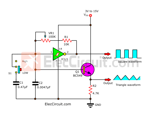
Basic diagram ICL8038 circuit Function generator. Figure 1 The basic circuit of function generator using ICL8038. The Basic characteristics of the circuit with a few components, it consists of the VR1-potentiometer, the R1-resistors and the C1-capacitors to determined frequency output. We can use the below formula to calculate the frequency.

Voltage Control Function Generator Circuit Of Ma709
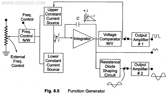
Aug 13, 2017 · The block diagram of a function generator is given in the figure. In this instrument, the frequency is controlled by varying the magnitude of the current that drives the integrator. This instrument provides different types of waveforms (such as sinusoidal, triangular and square waves) as its output signal with a frequency range of 0.01 Hz to.

Function Generator Circuit Elektronica Circuit Printplaat
A Simple yet Precise Function Generator for the Experimenter. The block diagram is shown in Figure 1 and the assembled unit in Photo 1.... final amplifiers and level adjustments and the Power Supply Board, which generates all the dc levels needed by the circuits. The generator is capable of outputting fixed or swept sine waves, square waves ...
Typical Rf Signal Generator
The complete circuit diagram for the AD9833 and Arduino Based Function Generator is shown below. We are going to use the AD9833 with Arduino to generate our desired frequency. And in this section, we will explain all the details with the help of the schematic; let me give you a brief overview of what is happening with the circuit.
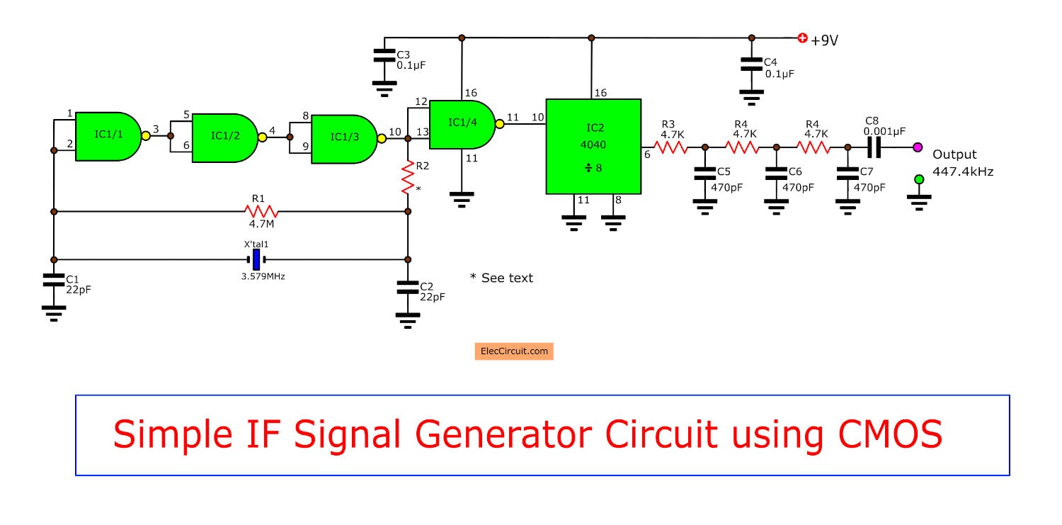
Simple If Signal Generator Circuit Using Cmos Ic Eleccircuit
Aug 11, 2015 · Mobile phones generally charge with 5v regulated DC supply, so basically we are going to build a circuit diagram for 5v regulated DC supply from 220 AC. This DC supply can be used to charge mobiles as well as the power source for digital circuits, breadboard circuits, ICs, microcontrollers etc.

Schematic Diagram Showing A Signal Generator Connected To An
Simple Function Generator Circuit Diagram in: Generator This is a simple function generator circuit that can produce the following waveforms: square wave, triangular wave, and sine wave. The circuit's main components are two 1458 IC's. The 1458 is a dual op-amp IC, i.e., an IC that houses two op amps inside it.
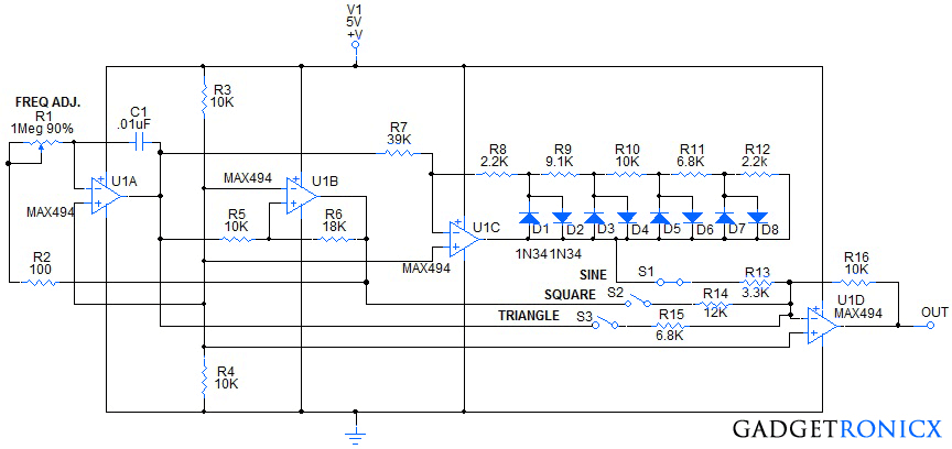
Function Generator Circuit Using Quad Opamp Ic Max494
Dec 03, 2018 · Variations of symbols will exist depending on function or other characteristics. Examples are Variable Battery symbol (5) and the Case Ground symbol (6) Electrical repair diagrams are mostly standardized for the above symbols. Auto Wire Diagram Advanced Symbols. Abbreviated codes on the diagrams provide a circuit path and part or component.
Function Generator Block Diagram Phase Locking In Function
This is the function generator working explaining with the block diagram. Abilities of Function Generator. As discussed, function generators hold the capability of generating multiple waveforms, and those are explained as below: Pulse Waveform - The pulse waveform is similar to the square waveform, but it has a space ratio of 1:1. This wave.

How To Build A Signal Generator Custom Maker Pro
Fiddler's Thinkings. In principle, the XR-2206 chip itself is a monolithic function generator integrated circuit capable of producing high quality sine, square, triangle, ramp, and pulse waveforms of high-stability and accuracy. The output waveforms can be both amplitude and frequency modulated by an external voltage.

Function Generator Circuit
The main function of a generator auto start is to automatically start & stop a generator. This is accomplished by following our generator auto start circuit diagram. Then, you are required to set up parameters and configure inputs connected to level switches, pressure switches, climate control systems, mains failure detection relays or other.
10 Useful Function Generator Circuits Explained Homemade
The Sweep/Function Generator as developed by L. J. Haskell was designed and built as a. Figure 1 - Circuit diagram schematic of DDS module. Figure 2 - Bottom view of DDS module Figure 3 - Top view of DDS module. First is to bring the RSET pin (12) out to connector. To free up the pin you have to cut the trace

Function Generator Block Diagram And Working Principle Etechnog
A simple function generator circuit using LM1458 is known here. LM1458 is a dual general purpose operational amplifier. The two opamps inside LM1458 has a common bias network, power supply line and are independent of each other in operation.

Function Generator Has Variable Frequency Edn
Dec 04, 2018 · Circuit Diagram. The complete circuit diagram this Arduino Function Generator is shown below. As you can see we have an Arduino Nano which acts as the brain of our project and an 16x2 LCD to display the value of frequency that is currently being generated. We also have a rotary encoder which will help us to set the frequency.
Square Wave Generator Using Op Amp Electronic Circuits
The full circuit diagram of the CMOS function generator as seen in the figure above. The integrator is entirely built using a CMOS inverter, Nl, while the Schmitt mechanism incorporates 2 positive feedback inverters. It's N2 and N3. The following image shows the pinout details of the IC 4049 for applying into the above schematic

Oscilloscope Circuit Diagram Function Generator Generator
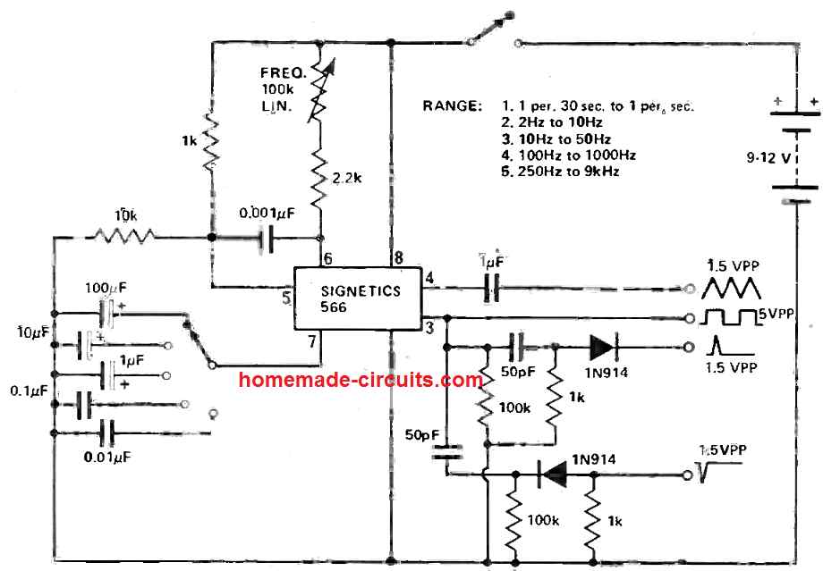
2. Function generator using op-amp LM1458. That circuit is based on a LM1458 or RC4558 capable of producing sine, square, triangular, sawtooth and pulse waveforms of high accuracy and stability…. 3. Simple Function generator by LM566. The simple Function generator two waveform, It produces triangle and square waves from 1Hz up to 1MHz.

23 Circuit Diagram Of The 9 14mhz Vco Function Generator
Yes, there are similar ICs that can be used as a function generator. You can use XR2206 IC too to generate the different waveforms. Circuit diagram: Here we'll see the circuit diagram that you can make for your homemade function generator with IC ICL8038. This circuit is not frequency tune-able.

Circuit Diagram For Function Generator Download Scientific
WORKING OF FUNCTION GENERATOR CIRCUIT: The heart of the function generator is the integrator, formed by U1A( IC MCP6024), R1, R2, S1- 6, C1 - 6, and the comparator with hysteresis, formed by U1B, R7, R8, R9, and R10. They work together in the following way.
How To Make My Own Function Generator Quora
Jul 17, 2020 · Square wave to Sine wave converter circuit is an important analog circuit that converts square waveforms to sine waveforms.It has a broad spectrum of applications in many different areas of electronics, such as in mathematical operations, acoustics, audio application, inverters, power source, function generator, etc.
1hz To 10mhz Sine Square Function Generator Based On The
e. Function Generator f. 1k resistor x 2 h. Various connectors (banana plugs-to-alligator clips) for connecting breadboard to power supply and for multimeter connections. 3. Theory a. The HP33120A Function Generator The front panel of your function generator is shown in Figure 1. This instrument outputs

Function Generator E Manuals
Block Diagram and Working of Function Generator. A frequency control network used here whose frequency is controlled by the variation in the magnitude of current. The current sources 1 and 2 drives the integrator. By using Function Generator, we can have a wide variety of waveforms whose frequency changes from 0.01 Hz to 100 KHz.
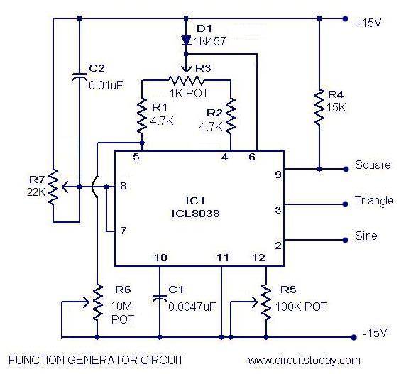
Function Generator Circuit Using Icl8038 Pulse Generator Ic
The circuit diagram of the function generator using LM1458 is shown below. function-generator-circuit. An operational amplifier LM1458 is a dual purpose operational amplifier and the bias network and power supply lines of these dual operational amplifiers are common. The four integrated circuits in the function generator circuit are IC 1a, IC.
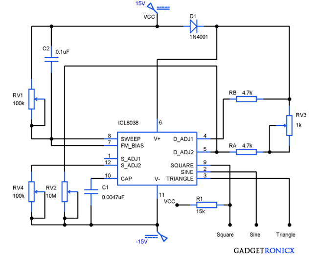
Function Generator Circuit Using Icl8038 Gadgetronicx
A plug-in circuit board (\breadboard") that can be used to wire up test circuits. BNC cables. You will need a few of these. There are a variety of lengths available on racks attached to the back side of the mobile whiteboard. Let's get started by looking at some function generator signals. 1. Turn on a function generator.
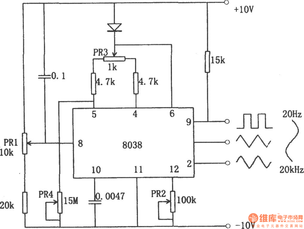
The Function Generator Using 8038 Function Signal Generator

Simple Function Generator Circuit Circuit Diagram

Signal Generator What Are They Circuit Amp Block Diagram

Function Generator Circuit Download Scientific Diagram

Signal Generator With Thyristor
20mhz Function Generator

Nonstop Free Electronic Circuits Project Diagram And
8038 Function Generator Circuit Automotive Circuit

How To Make A Signal Generator Function Generator Diy Sine Triangle And Square Waveforms
9v Battery Powered Function Generator Schematic
Function Generator Circuitlab
5 Function Generator Circuit Are Suitable For You

Schematic Diagram Simple Function Generator Wiring Diagram
Function Generator Using Icl8038 Electronic Circuits
Main Circuit Diagram Of Signal Generator Download
0 Response to "41 Function Generator Circuit Diagram"
Post a Comment