41 Fe Cr Phase Diagram
Mar 10, 2011 · Binary phase diagrams show the complete convex hull for the system, where the y-axis is the formation energy per atom and the x-axis is the composition (e.g. in the \(\ce{Fe-P}\) phase diagram, the x-axis is the fraction of \(\ce{P}\)). Figure 2: Calculated Fe-P Phase Diagram The Ti-Si-N-O quaternary phase diagram • Entire phase diagram can be calculated by taking into account all possible combinations of reactions and products • 4 ternary diagrams of Ti-Si-N, Ti-N-O, Ti-Si-O and Si-N-O were evaluated • additional quaternary tie lines from TiN to SiO 2 and Si 2N 2O A.S.Bhansali, et al., J.Appl.Phys. 68(3.
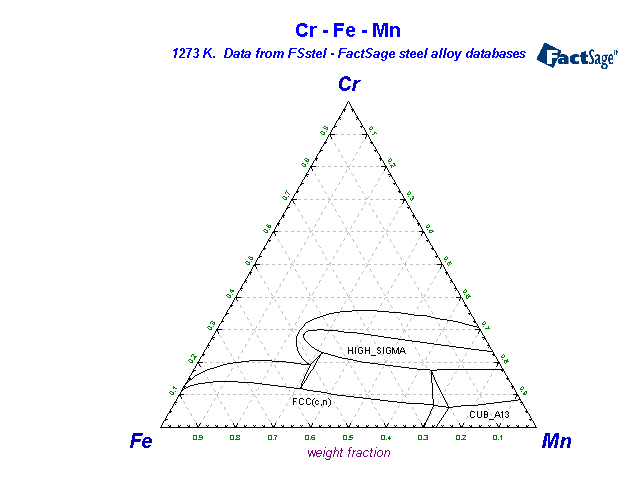
1273K-C-Cr-Fe FSstel: 1273K-C-Fe-Mn FSstel: Ag-Al FScopp: Ag-Al FTlite: Ag-Al SGnobl: Ag-Al SGTE 2014: Ag-Al SGTE 2017: Ag-Al SGTE 2020: Ag-Al-Au_500C SGnobl: Ag-Al-Bi_870C SGnobl: Ag-Al-In_650C SGnobl: Ag-Al-Mg_liquidus SGnobl: Ag-Al-Pb_870C SGnobl: Ag-Al-Si_500C SGnobl: Ag-Al-Si_liquidus SGnobl. Ag-Al-Sn_25C SGnobl: Ag-Al-Sn_liquidus SGnobl.

Fe cr phase diagram
@article{osti_7218909, title = {Phase diagram of Fe--Cr--Co permanent magnet system}, author = {Kaneko, H and Homma, M and Nakamura, K and Ikada, M and Thomas, G}, abstractNote = {The miscibility gap of the..cap alpha.. phase in Fe-Cr-Co permanent magnet alloys is constructed using mechanical hardness and Curie temperature measurements. . It is found that the miscibility gap of the Fe-Cr. SGTE Alloy Phase Diagrams. Click on a system to display the phase diagram. Download scientific diagram | 1: Fe-Cr phase diagram (a) [18]; Fe-Cr-.1C phase diagram (b) [19]. from publication: Alloy development for high Cr martensitic steel | Martensite, Steel and Alloys.
Fe cr phase diagram. Description. Phase diagram of Fe-Cr-.2%C.svg. English: Isopleth of ternary phase diagram of Fe-Cr-C at a constant 0.2 % C. The horizontal axis is mass percentage of Cr. This diagram was made by the uploader based on the figure in the following secondary source: 田中 良平(編). 2010『ステンレス鋼の選び方・使い方』改訂. File:Fe Cr phase diagram.svg. Size of this PNG preview of this SVG file: 747 × 478 pixels. Other resolutions: 320 × 205 pixels | 640 × 410 pixels | 1,024 × 655 pixels | 1,280 × 819 pixels | 2,560 × 1,638 pixels. 1. Locate composition and temperature in diagram 2. In two phase region draw the tie line or isotherm 3. Fraction of a phase is determined by taking the length of the tie line to the phase boundary for the other phase, and dividing by the total length of tie line The lever rule is a mechanical analogy to the mass balance calculation. English: The different version of File:Diagramme phase Fe Cr.svg.The horizontal axis label has been changed to English, and the blank space has been reduced. According to the description of File:Diagramme phase Fe Cr.svg, this diagram was made based on the source "Phase diagramme iron-chromium as per BAIN and ABORN - Metals handbook, American Society for Metals, 1948, 1194".
@article{osti_7218909, title = {Phase diagram of Fe--Cr--Co permanent magnet system}, author = {Kaneko, H and Homma, M and Nakamura, K and Ikada, M and Thomas, G}, abstractNote = {The miscibility gap of the..cap alpha.. phase in Fe-Cr-Co permanent magnet alloys is constructed using mechanical hardness and Curie temperature measurements. . It is found that the miscibility gap of the Fe-Cr. Aug 01, 2013 · In the present Co–Cr–Fe–Mn–Ni alloys, no phase separation was observed, even though they were furnace-cooled from homogenization temperatures. This can be understood based on two reasons. First, in HEA, the high mixing entropy enhances the mutual solubility between elements and the stability of solution phases [76]. 192 / Phase Diagrams—Understanding the Basics. A hypothetical ternary phase space diagram made up of metals. A, B, and . C. is shown in Fig. 10.2. This diagram contains two binary eutectics on the two visible faces of the diagram, and a third binary eutectic between ele-ments . B. and . C. hidden on the back of the plot. Because it is. PDF | On May 23, 2010, J. Carlos Rodriguez-Sebastián published The Fe-Cr-B phase diagram: Application to liquid phase sintering of Boron containing stainless steels | Find, read and cite all the.
Determination of the Fe-Cr-Ni and Fe-Cr-Mo Phase Diagrams at Intermediate Temperatures using a Novel Dual-Anneal Diffusion-Multiple Approach Cao, Siwei; Abstract. Phase diagrams at intermediate temperatures are critical both for alloy design and for improving the reliability of thermodynamic databases. There is a significant shortage of. An Ellingham diagram is a graph showing the temperature dependence of the stability of compounds. This analysis is usually used to evaluate the ease of reduction of metal oxides and sulfides.These diagrams were first constructed by Harold Ellingham in 1944. In metallurgy, the Ellingham diagram is used to predict the equilibrium temperature between a metal, its oxide, and oxygen — and by. Publication detail. Home. Rate this publication. Phase diagrams for FE-CR-NI based alloys. Part 1: Phase diagrams for binary and ternary alloys of FE, CR and NI with C and with SI. EU publications. Download Order. Fe-C diagram. 1. The Iron-Carbon Phase Diagram Prof. H. K. Khaira Professor in MSME Deptt. MANIT, Bhopal. 2. Iron-Carbon Phase Diagram • In their simplest form, steels are alloys of Iron (Fe) and Carbon (C). • The Fe-C phase diagram is a fairly complex one, but we will only consider the steel and cast iron part of the diagram, up to 6.
Chemengineering Free Full Text Novel Formation Of Ferrite
All the mentioned experimental results, that is, equilibrium phase compositions and composition of phases, were used to determine the isothermal section of B-Cr-Fe phase diagram at 1353 K that is shown in Figure 4. 4. Conclusions. In the work, phase equilibria of the B-Cr-Fe model alloys at 1353 K were studied experimentally.
Ternary Phase Diagrams
Phase Diagram www.factsage Section 8 Metal-oxygen diagram: Fe-O 2 Section 9 Ternary isopleth diagram: Fe-C-W, 5 wt% W Section 10 Quaternary predominance area diagram: Fe-Cr-S 2-O 2 Section 11 Quaternary isopleth diagram: Fe-Cr-V-C, 1.5% Cr, 0.1% V Section 12 Ternary isothermal diagram: CaO-Al 2 O 3-SiO 2 Section 13 Projections-Liquidus and First-Melting Section 14 Reciprocal Salt.
Analysis Of The Precipitation And Growth Processes Of The
Download scientific diagram | 1: Fe-Cr phase diagram (a) [18]; Fe-Cr-.1C phase diagram (b) [19]. from publication: Alloy development for high Cr martensitic steel | Martensite, Steel and Alloys.
Fsstel Factsage Steel Alloy Phase Diagrams
SGTE Alloy Phase Diagrams. Click on a system to display the phase diagram.

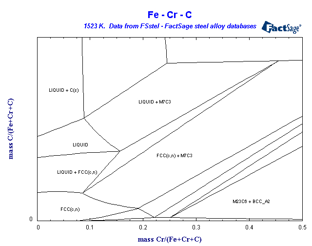
A Thermodynamic Evaluation Of The Fe Cr C System Sciencedirect
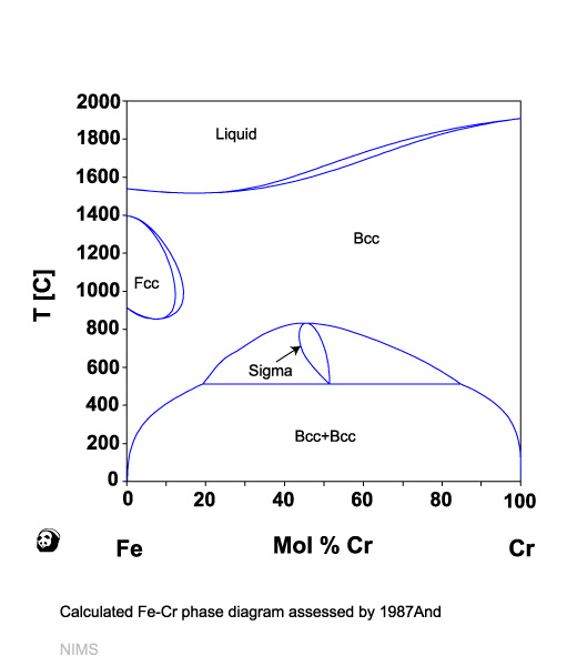
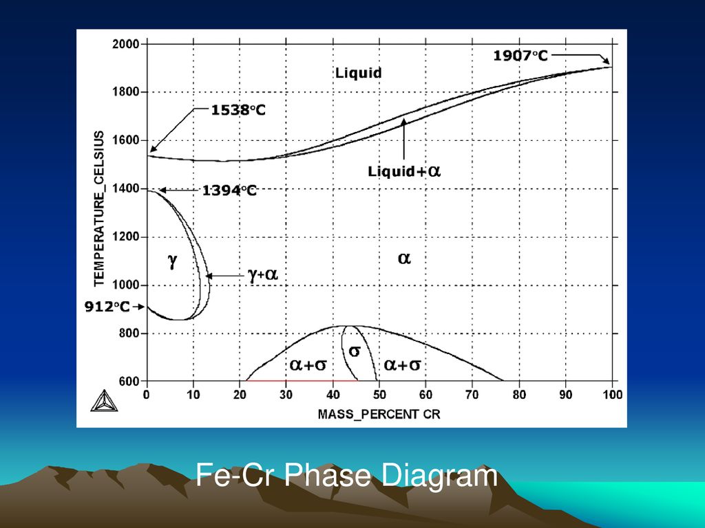
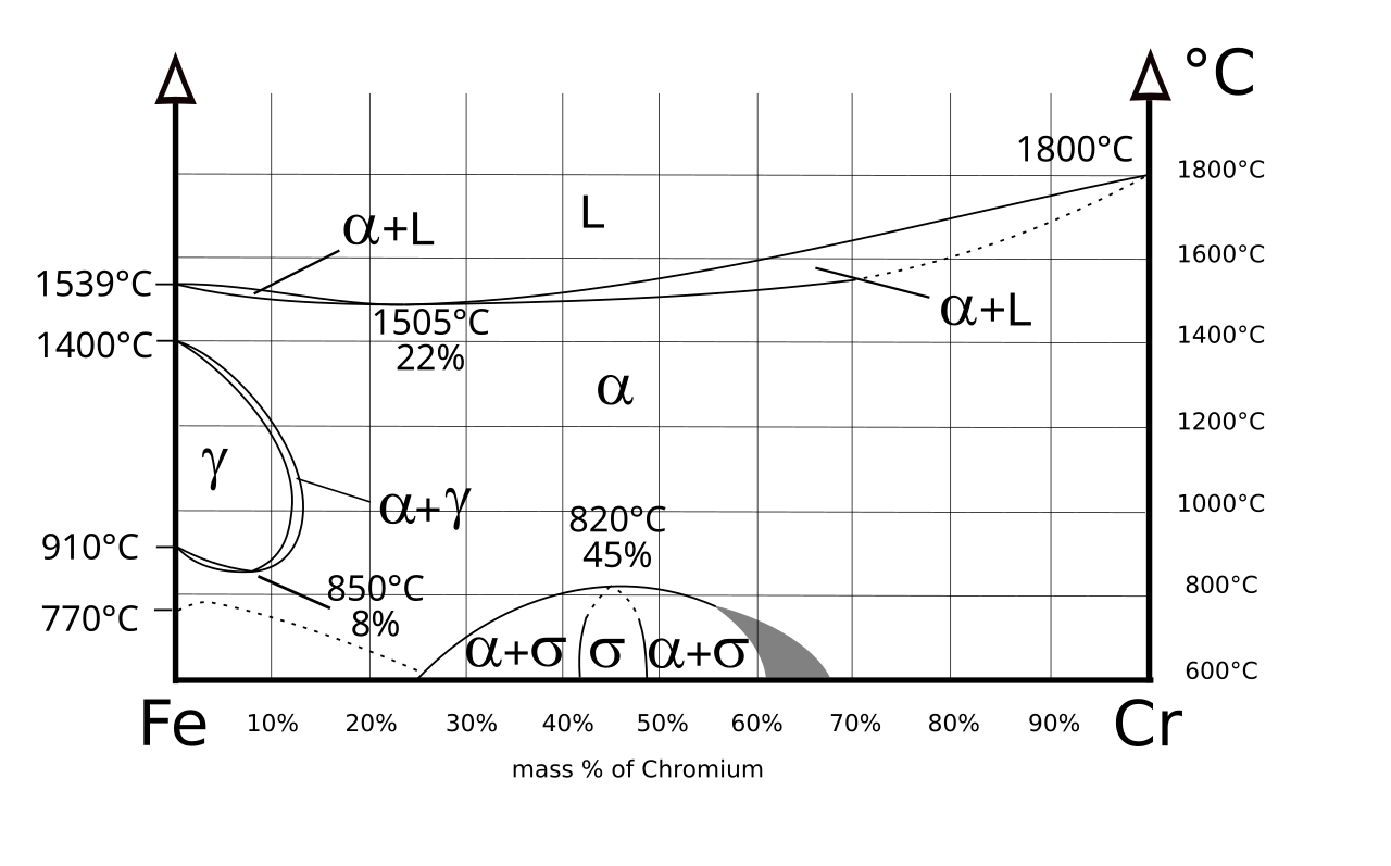
The phase diagram of the Fe-Cr binary system is at Fig 1. The melting point of Fe and Cr is taken at the pressure of 1 atmosphere as 1538 deg C and 1907 deg C respectively. The sigma phase, which is an intermetallic FeCr compound, can sometimes form in Fe-Cr alloys, such as AISI 316 or AISI 310 stainless steels.

Figure 12 Evolution Of Microstructure And Residual Stress
A finite-difference implicit numerical model was used to study the diffusion-controlled {alpha}{minus}{gamma} (ferrite-to-austenite) solid-state phase transformation in the Fe-Cr-Ni system. The influence of a nonuniform initial composition distribution was examined in order to assess the impact that.

File Fe Cr Ni Solidus Phase Diagram Svg Wikimedia Commons
The three-phase structure (γ 2 + D 3 + <Al 13 Fe 4 >) of the 70.0 Al–15.0 Cr–1 5.0 Fe and 71.3 Al–12.2 Cr–16.5 Fe alloys (Fig. 4d) and invariant effects at temperature close to 1085°C on.
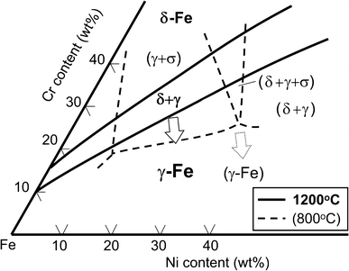
Figure 1 Overview Of Strategies For High Temperature Creep
By analogy with completely miscible binary alloy, the CrMnFeCoNi HEA can be described by a schematic phase diagram of the CrFeCo–MnNi system consisting of a liquidus and a solidus. When the cooling is slow enough, dendrites enriched in Cr, Fe and Co and interdendrites enriched in Mn and Ni are formed. –.
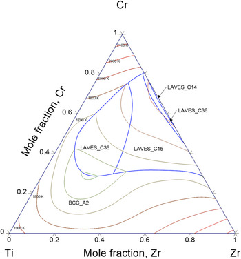
Thermodynamic Description Of Hydrogen Storage Materials Cr Ti
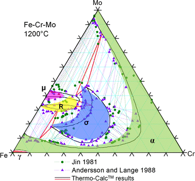
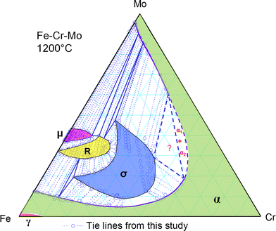
The Fe-Cr-Mo phase diagram contains two solid solutions (bcc (α) and fcc (γ)), four binary intermetallic compounds/phases (the σ, μ, λ (the Laves phase) and R phases), and one ternary phase (the χ (Chi) phase which was denoted as τ 1 in the early literature and in Ref 5). All the binary intermetallic phases have significant solubility of.
Cr Fe Nims
金属やセラミックスの状態図、エンリンガム図などの情報を提供しています。 一部、不確かなものもありますので、自己.

Fe Cr Ni Phasediagram Sections Youtube
The Fe-Cr-Mo ternary phase diagram is very significant to steel research and design since both Cr and Mo are key alloying elements of many steel compositions, especially stainless steels. Most steels are used at or below the intermediate temperatures (about 600-900 C for Fe-Cr-Mo), thus phase diagrams at these temperature ranges are
Modelling Phase Separation In Fe Cr Alloys
Iron-Carbon Phase Diagram. The iron-carbon phase diagram is widely used to understand the different phases of steel and cast iron. Both steel and cast iron are a mix of iron and carbon. Also, both alloys contain a small amount of trace elements. The graph is quite complex but since we are limiting our exploration to Fe3C, we will only be.

Factsage Com Phase Diagram Module
For "normal diagrams", where interested in all. components, use the . Normal equilateral . triangle. For diagrams where there is a major . component, e.g. Fe in Fe-C-Cr, use a . right-angled triangle →
Short Term Mechanical Properties Of Fe Cr Al Si Alloys Kne
Fe + Cr Nb + MO + Si Figure 3. Psuedo-Equilibrium Ternary Solidification Diagram for A718 Showing Solidification Path Direction from y to y t A,B Laves Phase (After Reference 5) Figure 3 also indicates that higher levels of Nb, MO, and Si promote the formation of Laves phase.
1 Fe Cr Phase Diagram A 18 Fe Cr 0 1c Phase Diagram B
SpMCBN - Spencer Group M-C-N-B-Si Alloy Phase Diagrams (837) Click on a system to display the phase diagram.

Example T 04 Ternary Phase Diagram
the ternary phase diagram with respect to the aus-tenite stabilized region in the low Cr composition has not beenentirely identified evenin the recent st.udy. Thepurpose of this study is to investigate the eq,ui-librium phasediagram of Fe-Cr-Mnsystem at 923 K (650'C), in particular, to examine the extent of a single phase reg_ion in the low Cr.

Influence Of Alloying Elements On Steel Microstructure
金属やセラミックスの状態図、エンリンガム図などの情報を提供しています。 一部、不確かなものもありますので、自己.

File Phase Diagram Of Fe Cr 0 2 C Svg Wikimedia Commons
3) Isothermal phase diagram of Fe-Cr-O system at 1 600°C was established. The relationshp between the chromium content of Fe-Cr melt and the oxide phase equilibrated was determined. below 1% Cr-cubic chromite, 1-7%Cr-c/a=1-0.95 above 7% Cr-Cr 2 O 3

Austenitic Steels Total Materia Article
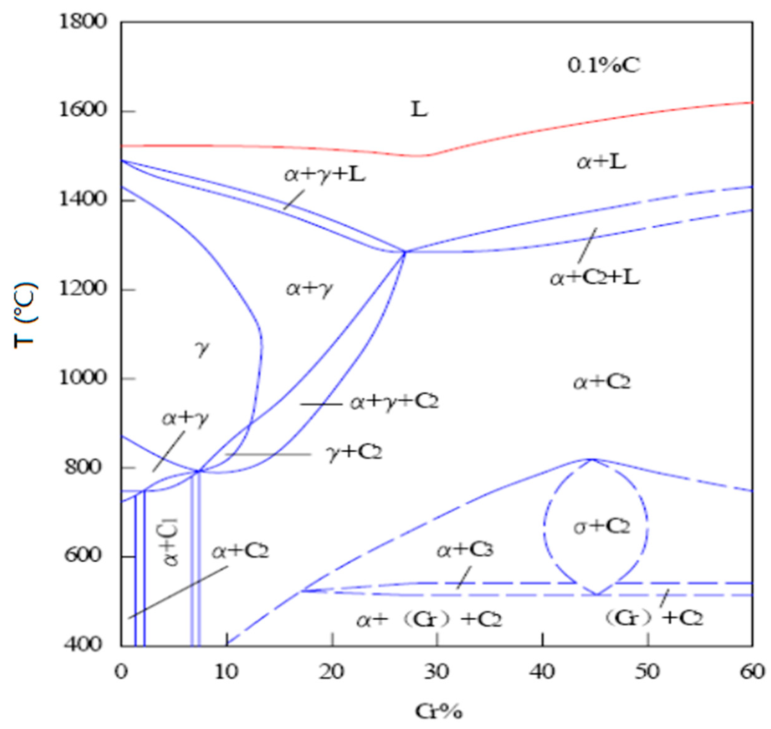
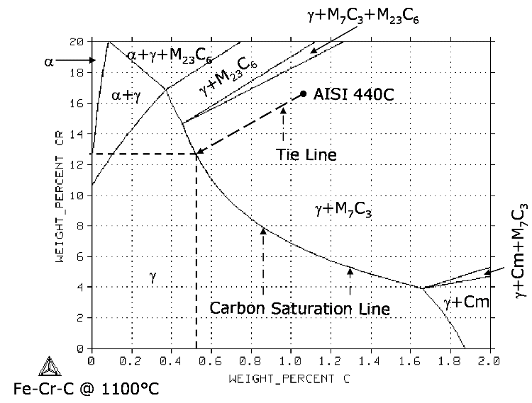
It is evident from Figure 6 (Fe-Cr-C phase diagram) that typical martensitic steels should exhibit ferrite and M 23 C 6 in equilibrium at for example, 600°C. In practice, this carbide is only found after relatively long ageing. because it is preceded by Intermediate phases in the sequence cementite, M 2 X and M 7 C 3 , leading finally to M 23.
Fsstel Factsage Steel Alloy Phase Diagrams
For the phase diagram calculations of Fe-Cr-Al alloy, we only consider bcc and bcc superstructures. The energy convex hulls of Fe-Cr, Fe-Al, and Cr-Al are shown in Fig. 2, and the formation energies for non-bcc stable structures FeAl 6-Cmcm, Cr 2 Al-I4/mmm, CrAl 3-I4/mmm and Cr 7 Al 45-C2/m from USPEX , calculations are also included. These non-bcc stable phases are consistent with the phases.
Experimental Investigation Of The Phase Relationship Of The
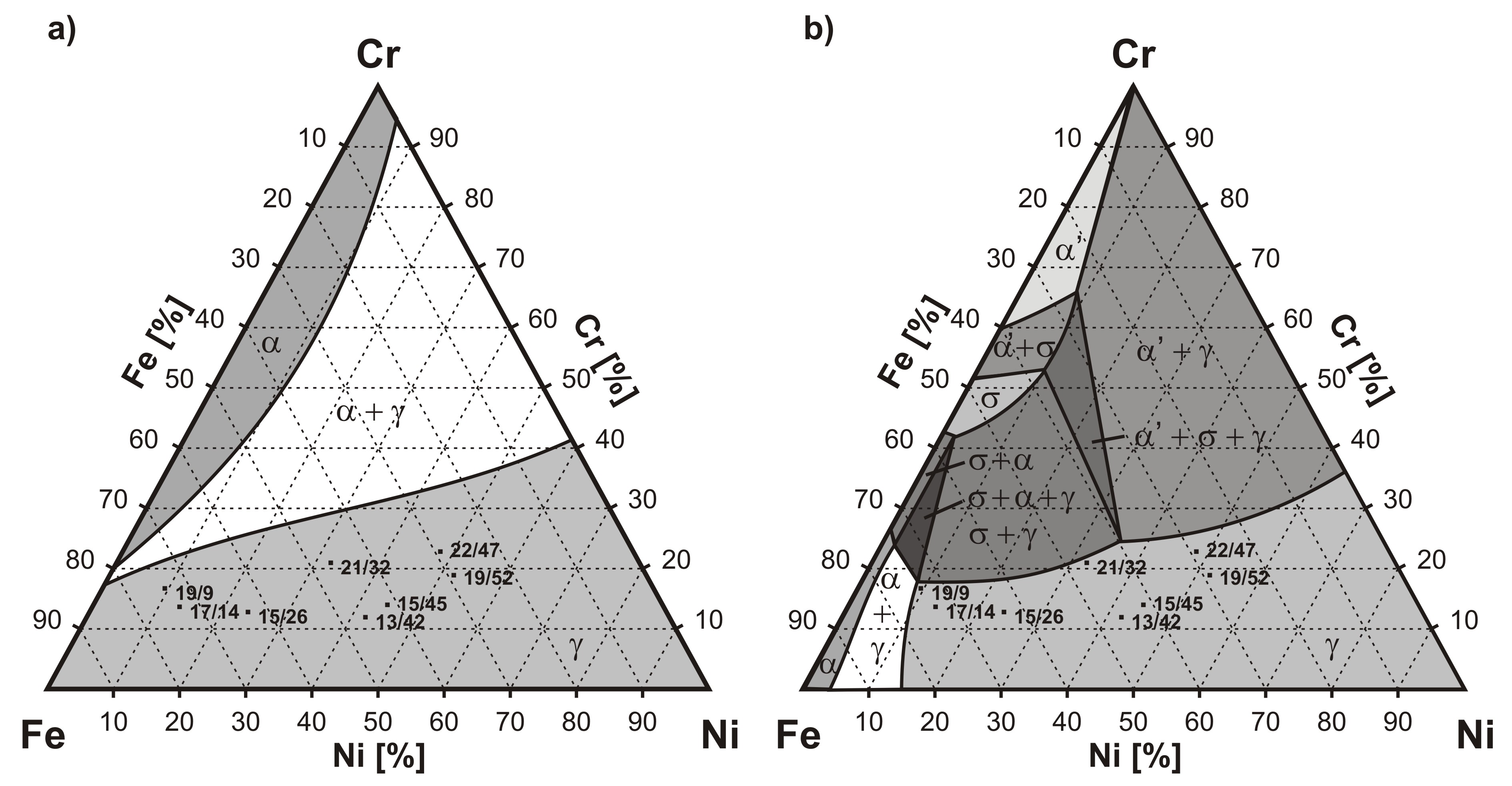
The four constituent binaries: Co-Cr, Cr-Fe, Cr-Mn, and Cr-Ni formed by adding Cr into the Co-Fe-Mn-Ni quaternary to form a quinary system. From the 10 binary phase diagrams shown in Fig. 3 , Fig. 4 , Fig. 5 , we reach the conclusion that if development of a simple fcc structure is the goal, the Co-Cr-Fe-Mn-Ni quinary is certainly a.
Determination Of The Fe Cr Mo Phase Diagram At Intermediate
Phase Diagram. このサイトを検索. Fe-Cr. Data from RICT-Sol alloy database ver.1.0. Sign in | Recent Site Activity | Report Abuse | Print Page | Powered By Google Sites...

Finomitas Fulke Ebredes Fe Co Ni Ternary Phase Diagram
Learn two simple ways to calculate a ternary phase diagram in the Fe-Cr-C system using the graphical mode of Thermo-Calc~~TIMESTAMPS~~0:00 Intro0:38 How to c...
Martensitic Stainless Steel For Knife Applications Part 1
Cr Si Mn W Mo Review Fe-C phase diagram • 2 important points-Eutectoid (B): γ⇒α+Fe 3C-Eutectic (A): L ⇒γ+Fe 3C Fe 3 C (cementite) 1600 1400 1200 1000 800 600 400 0 12 3 4 5 66.7 L γ (austenite) γ+L γ+Fe 3C α+Fe 3C α + γ L+Fe 3C δ (Fe) C o, wt% C 1148°C T(°C) α 727°C = Teutectoid A R S 4.30 Result: Pearlite = alternating.
Apa Yang Dimaksud Dengan Fase Terner Dan Diagram Fase Terner
Jul 01, 2004 · The fcc phase field includes the composition Fe 20 Cr 20 Mn 20 Ni 20 Co 20, and is capable of dissolving substantial amounts of Nb, Ti and V, as well as smaller amounts of Cu and Ge. It presumably extends to include the fcc austenite phase in pure Fe, pure Ni and binary Fe–Ni alloys.
Metals Free Full Text Study On S Phase In Fe Al Cr Alloys

Scielo Brasil Phase Transformations In An Aisi 410s

Fe Cr Binary Phase Diagram Adapted From Massalski See Ref 7

Phase Diagram Of The Ag2se As2se3 System And Crystal
What Are Stainless Steels Ppt Download

Physical Metallurgy 19 Th Lecture Ppt Video Online Download
Experimental And Numerical Modeling Of The Dissolution Of
Determination Of The Fe Cr Mo Phase Diagram At Intermediate

Journal Of Materials

Local Thermal Processing Effects In The Morphological
Phase Diagram Array

Phase Diagrams And Elastic Properties Of The Fe Cr Al Alloys
Sigma Phase In Fe Cr And Fe V Alloy Systems And Its Physical
File Phase Diagram Of Fe Cr Svg Wikimedia Commons

Cr Fe Phase Diagram And Database Gedb For Factsage

Ferritic Stainless Steel Wikiwand
0 Response to "41 Fe Cr Phase Diagram"
Post a Comment