41 6 Volt Positive Ground Wiring Diagram
Wiring Diagram 6 Volt Positive Ground 1/3 Download Wiring Diagram 6 Volt Positive Ground Free Car Alarm, Remote Start, and Car Stereo Wiring Disclaimer: * All information on this site ( the12volt ) is provided "as is" without any warranty of any kind, either expressed or implied, including but not limited to fitness for a particular use. Posted: Wed Jan 09, 2019 2:31 pm Post subject: Re: How to wire 6 Volt 1942 9N. Besides what HCooke said, the ground strap goes from the positive post to a bolt on the steering column and the negative cable goes from the negative post to the starter switch. Be sure to use the large gauge (small number) battery cable for 6 volt systems.
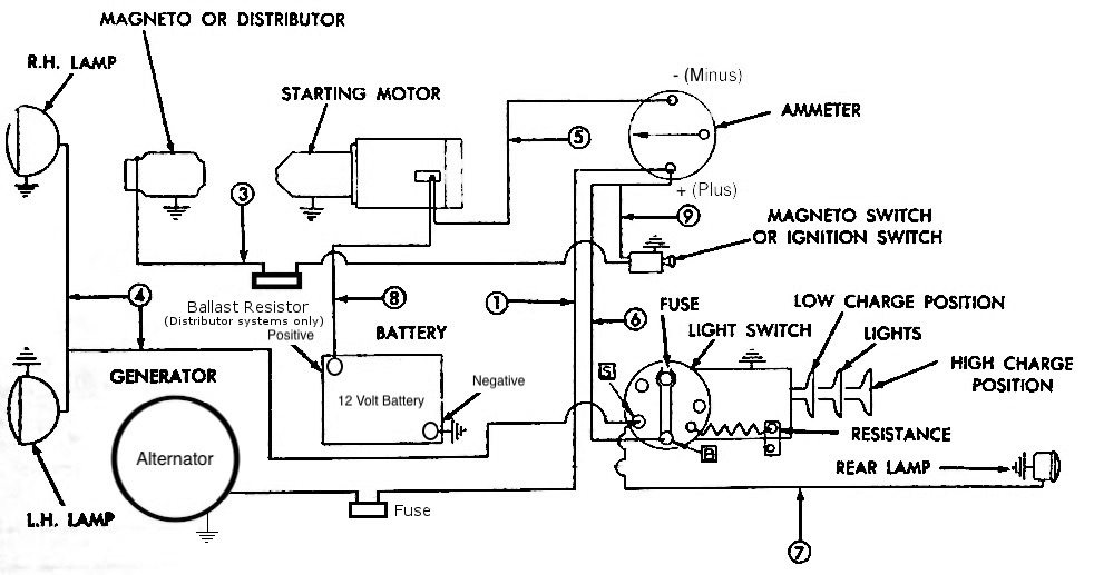
Positive Ground Farmall H Wiring Diagram 6 Volt from usguidebook eluxitalia.it. Print the wiring diagram off and use highlighters in order to trace the signal. When you employ your finger or even stick to the circuit with your eyes, it's easy to mistrace the circuit. One trick that We use is to print exactly the same wiring picture off twice.

6 volt positive ground wiring diagram
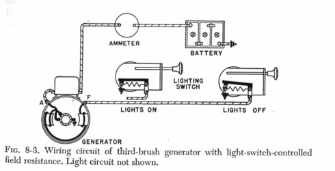
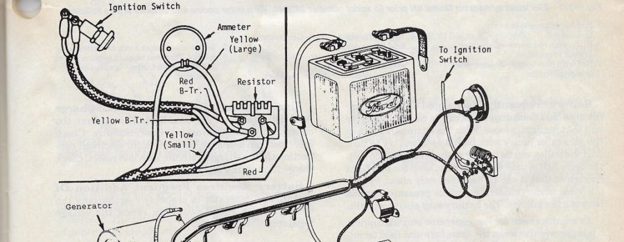
6 Volt Positive Ground or 6V Positive Chassis LED Lights, LED Bulbs, LED Lamps and LED Lighting Accessories. For cars, trucks, tractors and motorcycles. Thes... A positive ground system works by directly connecting the chassis of a vehicle to the positive side of the vehicle's battery. This system effectively earths the vehicle as the chassis attaches to the battery using a positive battery cable. The cable is tethered to the battery at one end and the engine block at the other. The positive ground. Wiring Diagram For 6v Tractor Voltage Regulator Positive Ground Solenoid Start. This walk-thru is based on the original 8N tractor 6 volt wiring. Many of those were later converted to the 8N type generator and voltage regulator, so this Two small screw terminals on the side of the generator are for "Ground" and " Field".
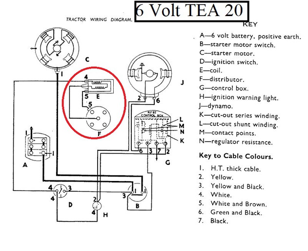
6 volt positive ground wiring diagram. The voltage regulator field. May 03, · Simple visual explanation of the wiring of the 6 volt Generator & Regulator on My Farmall Super A 6 Volt Positive Ground. may apply to others. Jun 20, · wiring diagram discussion in the Farmall & International Harvester (IHC) forum at Yesterday's Tractors. Ebm papst wiring diagram -6 volt positive ground wiring diagram bsa capacitior. 6 volt positive ground wiring diagram full hd quality version wiring diagram. 6 volt positive ground wiring diagram for chrysler -1995 3000gt engine diagrams. Dynamo regulator 6/12 volt positive earth product code: drp. http://alternatorparts /Delco-Remy GM type 6 volt positive ground 10si alternator conversion Be certain that any wiring you've done is at LEAST as big as what your Ford came with to keep from choking the system.Usually the culprit is in the ground…. or rather the lack of. The 6 volt battery should have the positive battery cable connected directly to the frame. Naturally the frame under the cable needs to be scraped bare and bright.
Feb 22, 2009 · gordon, i just put a radio in my 92 jeep wrangler and i was having same problems, if you look under the dash on each side where the speakers are you can see which colored wires are which that go into the speaker. and btw every wiring diagram ive looked at says the hot wire for the radio is gray.. mine is pink.. so be careful of that.. the ride positive should be white w/ red stripe. negative. 8n ford tractor wiring diagram 6 volt - You will need a comprehensive, expert, and easy to know Wiring Diagram. With this kind of an illustrative guide, you will have the ability to troubleshoot, stop, and total your tasks easily. Not just will it assist you to achieve your required outcomes faster, but additionally make the whole procedure. Nov 05, 2020 · In the above diagram, I have shown a single pole double throw relay (5 pin relay). Not that his relay can be 5 volts DCV, 12 volts DCV, 24 Volts DCV, etc according to ratting voltage of coil. in the above 5 pin relay diagram 1 and 2 pins for coil, 3 is the common pin, 4 is normally close and 5 is normally open pin. Aug 15, 2010 · OK, I'll bite. This stuff is all very simple, and there isn't really a "standard diagram". Basically all small boats just run a heavy (6 AWG should be more than sufficient, 30 amps for 23 ft.) positive and negative cable from the battery to a fuse panel/ terminal strip. Everything else is.
6 Volt Positive Ground Wiring Diagram – 6 volt positive ground generator wiring diagram, 6 volt positive ground wiring diagram, Every electrical arrangement is made up of various distinct pieces. Each component should be set and linked to different parts in specific manner. Otherwise, the structure will not work as it should be. To wire it in, unhook the wires from the voltage regulator, cut the ends and. the negative went to the starter solenoid and electrical system. Chevrolet and most For the positive ground vehicles going to negative ground, everything in your vehicle will work as it does today. removing from the vehicle, remove the 6 volt voltage regulator diagram. Wiring diagram for 1951 COE Truck. Wiring diagram for 1953-55 Truck. Wiring Schematics - Mercury. (showing the electrical path and connections) Wiring for 1939 Mercury. Wiring for 1940 Mercury. Wiring for 1941 Mercury. Wiring for 1942 Mercury. Wiring for 1946 to 48 Mercury. Harness Wiring. Note: This is a general wiring diagram for automotive applications. Use as reference only.. Connect the RED wire to the positive (+)... Use wire ties to secure any slack portion of the 12 volt connection or wire harness in the engine compartment away from moving parts or excessive heat.
EZGO 36 volt solenoid wiring diagram. The easiest way to wire a solenoid on a 36-volt EZGO golf cart is to follow the solenoid wiring diagram for the cart. This diagram gives a clear illustration of the wiring connections made from and to the solenoid. In most carts, the wiring is very straightforward and simple.
6 Volt Positive Ground Wiring Diagram– wiring diagram is a simplified conventional pictorial representation of an electrical circuit.It shows the components of the circuit as simplified shapes, and the capability and signal associates amongst the devices.
A positive ground system works by directly connecting the chassis of a vehicle to the positive side of the vehicle's battery. This system effectively earths the vehicle as the chassis attaches to the battery using a positive battery cable. The cable is tethered to the battery at one end and the engine block at the other. The positive ground.
Charlie S Wiring Schematics Model 1. Farmall cub wiring diagram regulator h for 6 volt 6v cutout and delco remy 1950 a t i s faq on cubs page 2 alternator conversion m step by 12 light switch technical ih good battery 12v 49 help to 1949 ford 8n chrysler convert tractor new jvc al e500 charlie schematics model 1 22 transmission super c 47 53 08 onan starter solenoid nissan frontier pcm.
May 04, 2020 · Convert a Negative Output to a Positive Output Relay Wiring Diagram: If you have a switch or an alarm or keyless entry that has a negative output that you wish to use to switch a device that requires 12V+ such as a horn, dome light, parking lights, head lights, hatch release, etc., wire a relay as shown below to convert the negative output (trigger) to a positive output.
Nov 18, 2020 · 48 Volt Golf Cart Battery Wiring Diagram from images-na.ssl-images-amazon Print the electrical wiring diagram off and use highlighters to be able to trace the circuit. When you use your finger or follow the circuit together with your eyes, it is easy to mistrace the circuit. 1 trick that I 2 to printing a similar wiring diagram off twice.
Mar 22, 2010 · This is a diagram for a p-15 but hopefully it will help a little. Quote; Link to post. I have a 6 volt alt, am I still positive ground? Depends on the alternator you are using. The first 6V alternators were negative ground, later they came out with positive ground.... I should look at the wiring and follow the connections and see what the ...
6 Volt Positive Ground Wiring Diagram Source: static-cdn.imageservice.cloud. READ 1994 Dodge Dakota Wiring Diagram For Your Needs. Before reading the schematic, get acquainted and understand all of the symbols. Read the schematic like a new roadmap. I print out the schematic plus highlight the circuit I’m diagnosing to make sure Im staying on.
Airtex 6-volt pumps will work with either positive or negative ground. When installing one of these pumps on a positive ground system, install the positive wire of the pump to the vehicles chassis ( remember the body of the Airtex unit is not part of the circuit ), then wire the black wire back to the negative side of the battery.
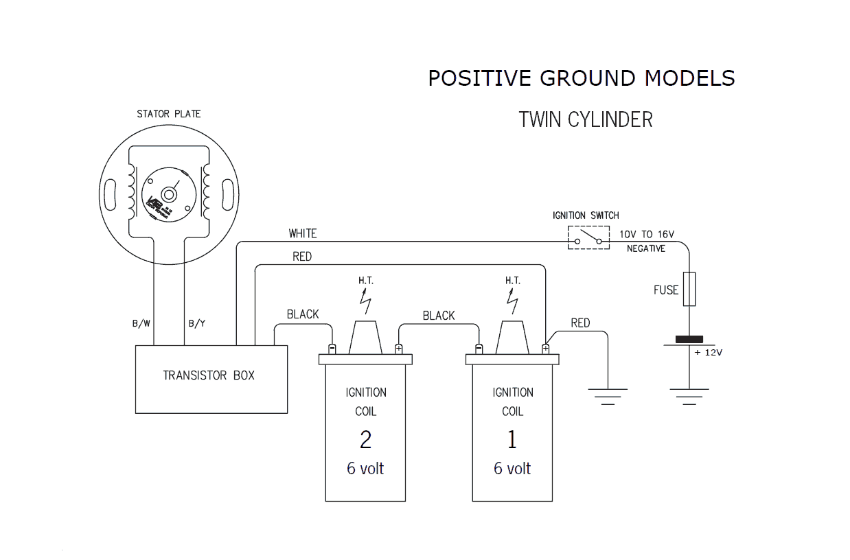
Wiring schematic for 6 volt, Positive Ground, Pertronix Ignitor ( 1188P6 ) Original wiring is from IGN switch (coil term) to (-) term on 6 volt coil. (+) term on 6 volt coil to distributor, to points, which are grounded on one side. New schematic-. Connect IGN switch (coil term) to black wire from ignitor module / the Black/ white wire from the.
Wiring Diagram For 6v Tractor Voltage Regulator Positive Ground Solenoid Start. This walk-thru is based on the original 8N tractor 6 volt wiring. Many of those were later converted to the 8N type generator and voltage regulator, so this Two small screw terminals on the side of the generator are for "Ground" and " Field".
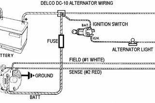
6 Volt Alternators Positive Ground. We have taken the very reliable Delco 10SI alternator and configured it to provide higher amperage power for 6-volt applications. Now you can replace your old generator and not have to worry about rewiring the rest of the vehicle. This alternator has a 1-wire regulator so your only connection is a battery.
farmall a tractor 6 volt positive ground wiring diagram wiring. Architectural wiring diagrams sham the approximate locations and interconnections of receptacles, lighting, and remaining electrical facilities in a building. Interconnecting wire routes may be shown approximately, where particular receptacles or fixtures must be upon a common circuit.
Jan 13, 2016 · 2018-2020 Chevy Silverado Stereo Wiring Diagram. The wiring for the 2018 and 2019 Silverado can vary, depending on the level of your trim. If your Chevy Silverado has a 16-pin plug on the back of your stereo, you will need to follow this guide instead of the previous one. Silverado Stereo Constant 12V+ Wire: Red/Violet
1. See figure B for wiring diagram. 2. Remove the ignition switch wire from the negative coil terminal. 3. Connect the black Ignitor wire directly to the ignition switch wire. 4. Connect the Ignitor black/white wire to negative (-) side of the ignition coil. 5. Connect an insulated, AWG 20 copper stranded wire from the positive coil terminal to.
6 volt positive ground wiring diagram – You will need a comprehensive, skilled, and easy to comprehend Wiring Diagram. With this sort of an illustrative manual, you will have the ability to troubleshoot, stop, and complete your tasks with ease. Not only will it help you accomplish your desired outcomes more quickly, but also make the complete.
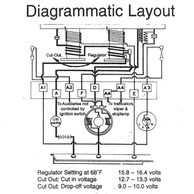
6 Volt Positive Ground Voltage Regulator Wiring Diagram from homemade-circuits . Effectively read a cabling diagram, one has to learn how the components inside the method operate. For instance , in case a module is powered up also it sends out the signal of fifty percent the voltage in addition to the technician does not know this, he'd.
1. See figure B for wiring diagram. 2. Remove the ignition switch wire from the negative coil terminal. 3. Connect the black Ignitor wire directly to the ignition switch wire. 4. Connect the Ignitor black/white wire to negative (-) side of the ignition coil. 5. Connect an insulated, AWG 20 copper stranded wire from the positive coil terminal to.
Description : Ford 6 Volt Positive Ground Wiring Diagram Gmc Truck Radio Wire inside 6 Volt Positive Ground Wiring Diagram, image size 3804 X 1968 px, and to view image details please click the image. Here is a picture gallery about 6 Volt Positive Ground Wiring Diagram complete with the description of the image, please find the image you need.
true for wiring: because 6-volt systems require higher amperage to operate, wiring within such a system essentially is two times larger than that required for 12-volt systems. This is why you are able to use the same wiring and mechanical switches in a 12-volt system as in a 6-volt system.
Search: 6 Volt Positive Ground Voltage Regulator Wiring Diagram
8N Ford Tractor Wiring Diagram 6 Volt. Print the wiring diagram off plus use highlighters to trace the signal. When you make use of your finger or perhaps the actual circuit with your eyes, it is easy to mistrace the circuit. 1 trick that We 2 to printing a similar wiring plan off twice.
Plus, the bigger wire is stronger, carries more current, and causes less voltage drop. I use the same sizes for 12 volt wiring for all the same reasons. We could go smaller for a 12 volt system, but if someone decides to switch back to a 6 volt system, the wiring would all have to be changed.
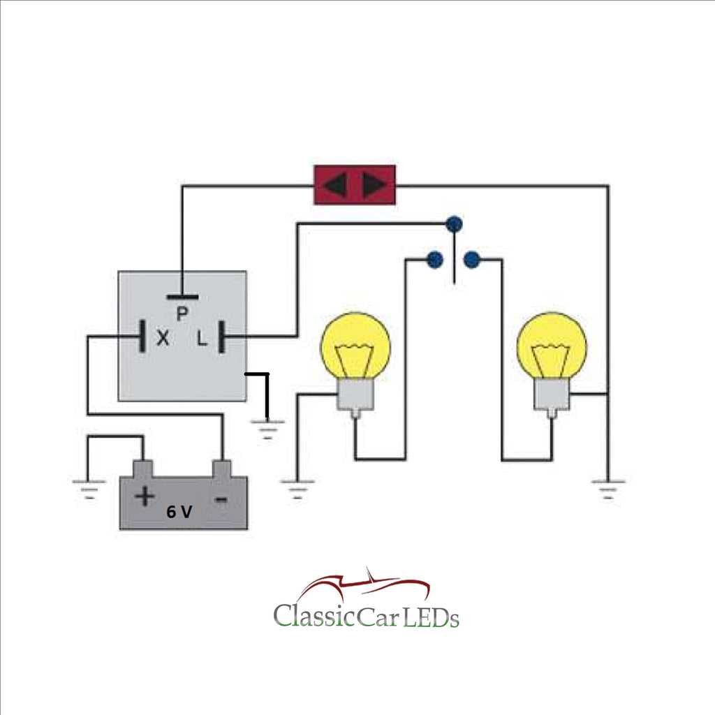
I bought an aftermarket turnsignal swith the other day for my 53 Dodge wich still has the 6 volt positive ground system. I wired the turnsignal switch in and bought a six volt flasher. I have checked and rechecked all my wires. It is wired like the diagram says to wire it. I have 6volt dual element bulbs in it.

Db Electrical Gdr6003 6 Volt Regulator Compatible With Replacement For Generator Two Unit A Circuit Positive Ground 1116807 1116816 1118291
6 Volt Positive Ground or 6V Positive Chassis LED Lights, LED Bulbs, LED Lamps and LED Lighting Accessories. For cars, trucks, tractors and motorcycles. Thes...
6v positive ground wiring diagram.Here is a diagram for the regulator equipped three position Farmall with a MAG. It shows the components of the circuit. 6 Volt Positive Ground Wiring Diagram 6 volt positive ground generator wiring diagram 6 volt positive ground wiring diagram Every electrical arrangement is made up of various.
Ignition Coil Wiring. If your original ignition coil is positive ground the positive terminal of the coil should be connected to the distributor. The negative terminal of the coil should be connected to the ignition switch. When you upgrade to 12-volts and replace your original 6-volt positive ground ignition coil with a modern 12-volt ignition.








0 Response to "41 6 Volt Positive Ground Wiring Diagram"
Post a Comment