41 4 Way Valve Diagram
4-Way solenoid spring return valve with 1/8" external pilot dual pressure application. shown in the de-energized condition. When energized the valve will shift it's flow paths and lower the axle. #320148. Brass adapter allows full line pressure to shift valve manually (install finger tight & seal Full Product Description. Parker's 4-Way, 2 Position, Single Operator, 1/4" NPT Solenoid Valves are used in applications for actuation of double acting cylinders and piloting of larger control valves. Ideally suited for general purpose air, liquids and gases, these valves are available in brass construction with NBR seals.
CHECK VALVE TO 4 FUNCTION FILL VALVE FROM CHECK VALVE TANK TO COLD FIXTURES AIR VENT FOR TANK 0 Anderson @Anderson Brass Company. TO TANK 0 Anderson O L—T0COLDFlXWRES o . Author: Bryan Created Date:
4 way valve diagram
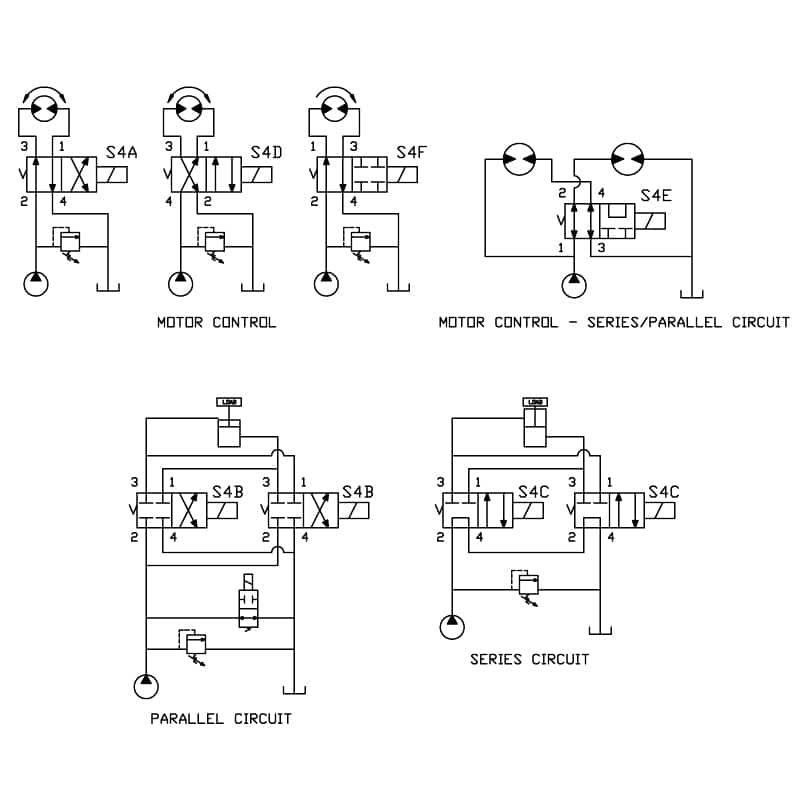
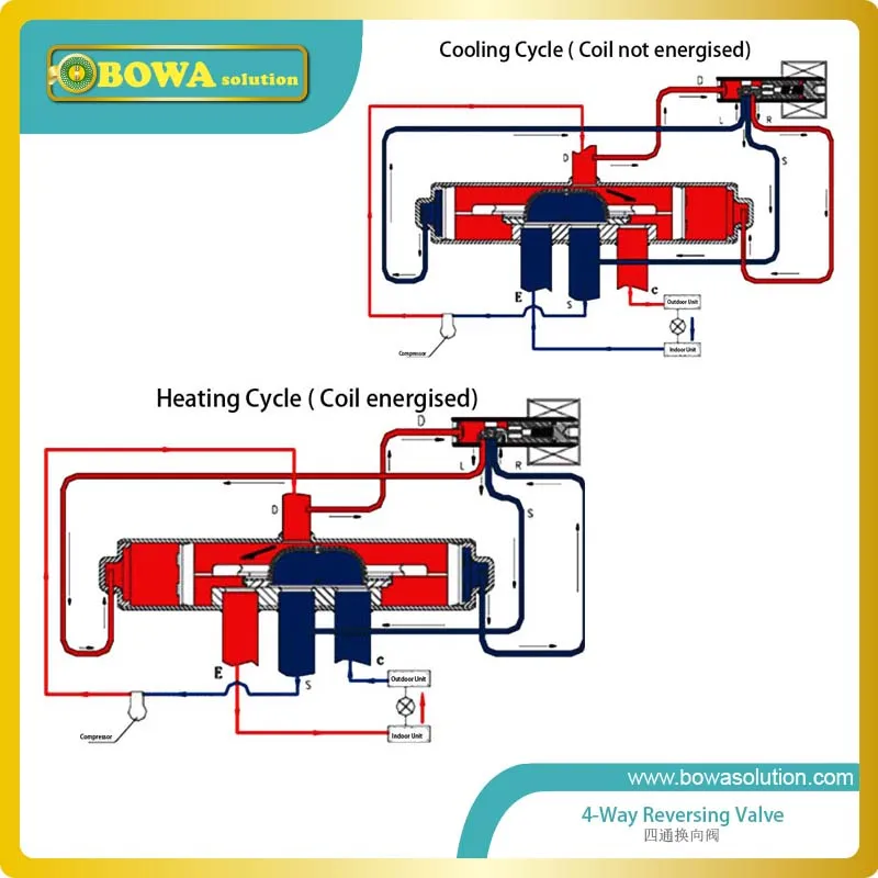
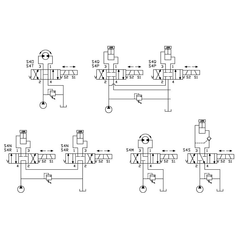
4-way Solenoid Valve. The following diagram shows a 4-way solenoid valve connected to the piston actuator of a larger (process) ball valve: The same diagram could be drawn using the "triangle" solenoid valve symbols rather than the "block" symbols more common to fluid power diagrams: 4/2 way valve. 4 ports 2 positions. 4/3 way valve. 4 ports 3 positions. 5/2 way valve. 5 ports 2 positions. 5/3 way valve. 5 ports 3 positions. Mechanical valve symbols.. An engineering line diagram of P and ID will show more detailed and precise information. Get In Touch. Address: Yate, Bristol, UK. Phone:+44 (0)1454 334 990. E-mail ... 4-Way Reversing Valve with operating control used for heat pumps. This is called the 4-Way Reversing Valve, because it has four connections refrigerant pipes.Because the heat pump uses of reversible mechanical refrigeration cycle, such device is not required. Shown here, the heat pump cooling works like any cooling system when it is in cooling mode.
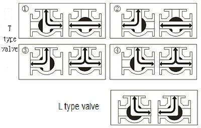
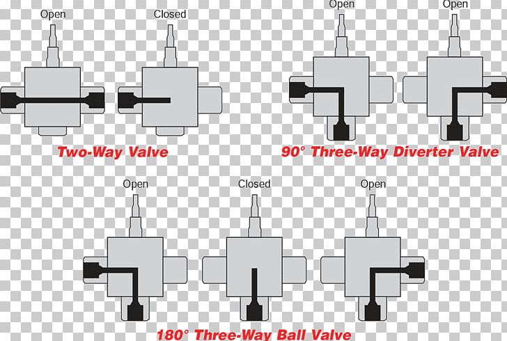
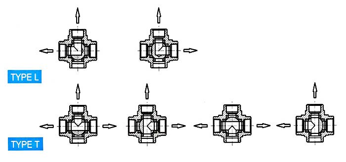
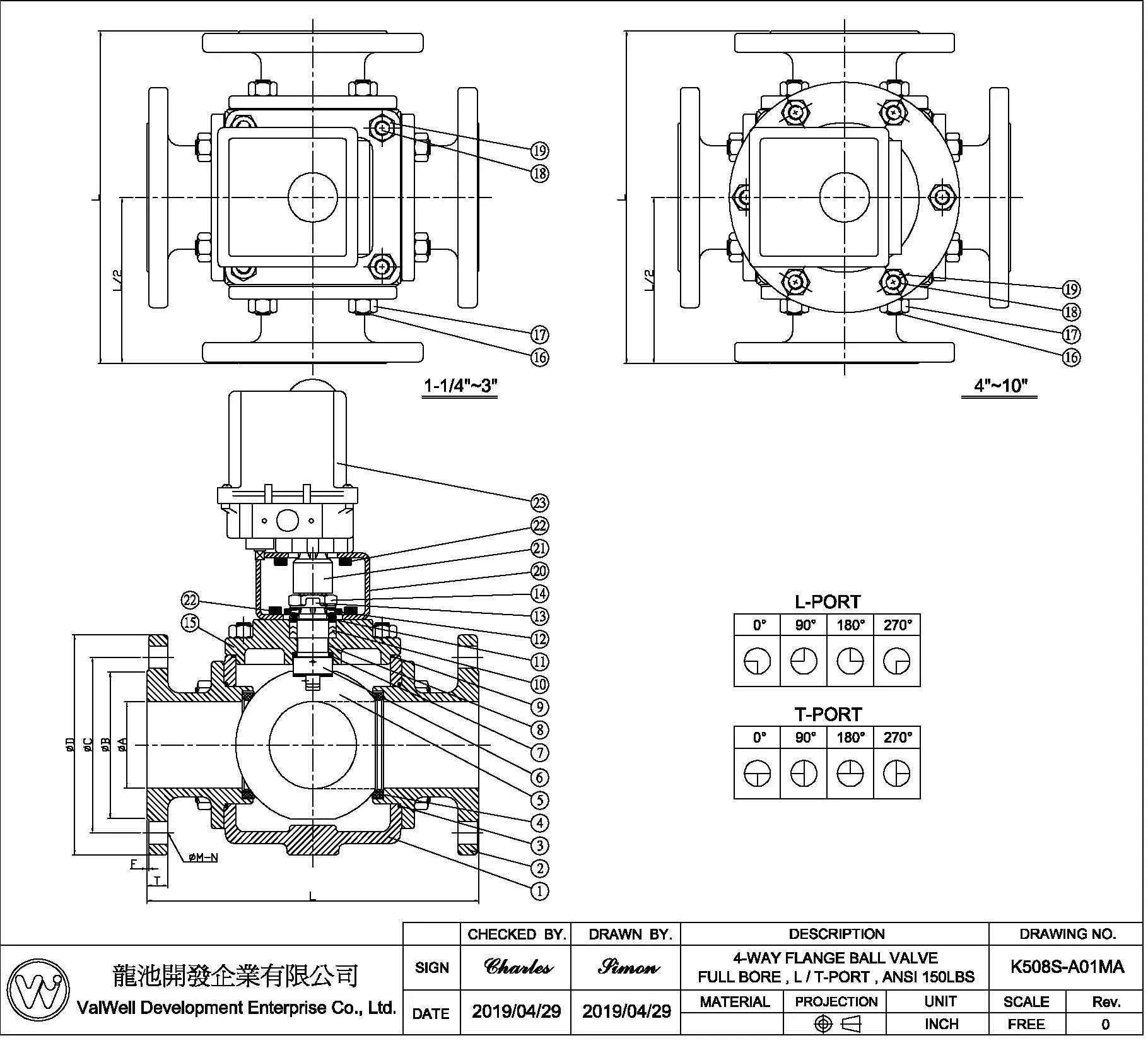
4 way valve diagram. 4-WAY: 90ϒ 1 2 P 4-WAY: 270ϒ 1 23 4 Off Position Features Stem Seals Multiport Series 1/ 4”–4” valves all feature a live-loaded stem packing assembly for positive sealing. Utilizing belleville washers, the stem seal automatically adjusts to compensate for changes in temperature and normal wear. The 6”– 12” valves utilize an. An L-pattern flow three-way horizontal version ball valve has two potential shut-off positions. With a four-position valve, these two valve shutoff positions are only 90 degrees or a quarter turn apart. Most horizontal type L pattern flow valves will have handles that are limited to 180 degrees of turn. Anderson 4 way valve Flow Diagram.pdf. 17 May 2018 10:19. 485.7 Kb. Anderson 4 way valve Kantleak RV200 cartridge instructions.pdf. 17 May 2018 10:19. 285.9 Kb. Anderson 4way valve contact and video link.pdf. 17 May 2018 10:19. 10.2 Kb. 4 WAY BALL VALVE Owner’s Manual MODELS: SP0735 AND SP0735S IMPORTANT SAFETY INSTRUCTIONS Basic safety precautions should always be followed, including the following: Failure to follow instructions can cause severe injury and/or death. This is the safety-alert symbol. When you see this symbol on your equipment or in this manual, look for
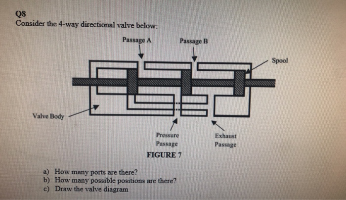
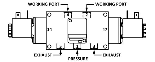
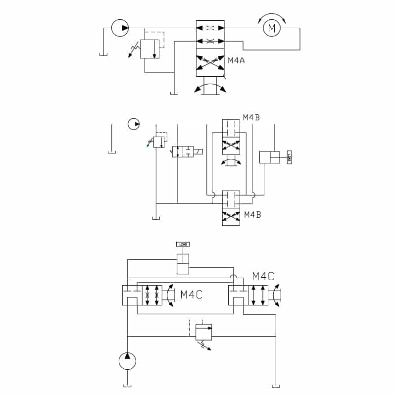
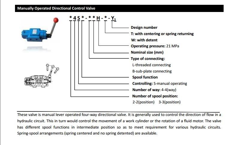
In this lecture you will learn about 1. Spool Type Direction Control Valve.2. Comparison Between Actual Valve & Circuit Symbols.3. Actual Working & Cross sec... Spool Valves, 4-Way, 5-Port The 4-way spool valve can be controlled by using two operators, one on each end or by a spring return and a single operator. The flow path when actuated at the 14 end of the valve is from port 1 to port 4 and from port 2 to port 3. Port 5 is blocked. When the valve is actuated from the 1 2 end, the flow path Four-way valves consist of a rectangular cast body, a sliding spool, and a way to position a spool.. In diagram B, port P is open to port B, and the piston moves to the left. Return flow from the cylinder passes through ports A and T. Table 5-1, lists some of the classifications of directional-control valves. These valves could be identified... These valves are also known as cartridge valves, and they screw into your mounting block. Place four-way valves between the pressure source and a double-acting cylinder. In NFPA diagrams, P represents the pressure source, T represents the tank, and A and B represent work ports. For technical drawings and 3-D models, click on a part number.
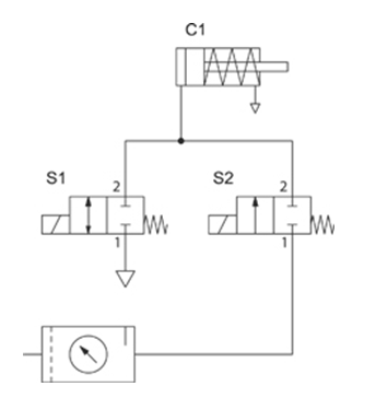
4/2 Valve. 4 Ports 2 Positions. Roller One Way. Shuttle Valve.... The spring "pushes" from the side it is drawn on and places the right side block diagram of the valve in function. The T Symbol. This symbol indicates that a port is closed and is neither passing or exhausting gas. The difference between the two valve types is the number of exhaust ports: A 5/2-way pneumatic valve has two independent exhaust ports. A 4/2-way valve has only one common exhaust port. Valve symbol of a mono-stable 4/2-way valve with ISO and alternative port designation. This means that both port (A,2) and (B,4) connect to exhaust port (R,3). It has five ports, but it is considered a 4-way valve because two of the ports share the same exhaust function. This is a holdover from hydraulics - where the two exhaust paths are joined (internally to the valve), so that only one return port is required, and only one return line is required to get the hydraulic oil back to the storage tank. 4/2-way and 5/2-way valves 4/2-way and 5/2-way, as well as 4/3-way and 5/3-way valves are usually used to control double acting actuators. In the example below a manually actuated valve (S1 or S2) controls a double acting cylinder (C1 or C2). Additionally, in order to control the speed of th e cylinder, flow control silencers are in use.
"C/CW/CC" Series Air Control Valves 3-Way, 3-Port, 2-Position 4-Way, 4-Port, 2-Position Catalog 0640-E/USA April 2004
c. Throttled valve d. Combination valves (3- or 4-way valve) e. Locked-closed valve f. Locked-open valve g. Fail-open valve h. Fail-closed valve i. Fail-as-is valve 1.10 Given an engineering P&ID, IDENTIFY components and DETERMINE the flowpath(s) for a given valve lineup. 1.11 IDENTIFY the symbols used on engineering fluid power drawings for the
Components for heat pumps - part 5: four-way reversing valves. Sunday, July 1, 2012. Four-way reversing valves are used to completely reverse the cycle of one-to-one heat pump systems. Such valves may be used to facilitate using the system for both heating and cooling, or to provide an effective and energetically optimized defrosting method.
Working of 4 way valve. In this Post you can learn that how working 4 way valve in Cool mode and Heat mode with Diagram. After see this Diagram i hope that you can under stand that how work 4 way valve and how AC do cool and heat. Diagram Cool Mode 4 way valve. Diagram Heat Mode 4 way valve. HVAC and RAC Learn platform. You can Also Subscribe.
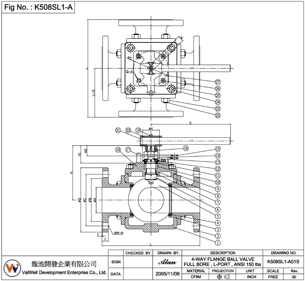
The M&J 4-Way Diverter Valve is a wide-angle, tapered, lift plug type 4-way valve with raised face flange ends. It is designed to operate with a lift/turn operator mechanism which may consist of a manual handwheel, electric motor, hydraulic motor, or electro-hydraulic (EH) with separate seat/unseat and rotary operators 3. Characteristics
The heart has four valves - one for each chamber of the heart. The valves keep blood moving through the heart in the right direction. The mitral valve and tricuspid valve are located between the atria (upper heart chambers) and the ventricles (lower heart chambers).. The aortic valve and pulmonic valve are located between the ventricles and the major blood vessels leaving the heart.
Route a 3/4″ mixed water supply line to the transfer valve location. Apply thread sealant to the inlet port threads and connect the water supply to the valve inlet. Two-Way: If two accessories will be attached to the valve, go to the ″Two-Way Installation″ section. Three-Way: If three accessories will be attached to the valve, go
4/2 way valve. 4 ports 2 positions. 4/3 way valve. 4 ports 3 positions. 5/2 way valve. 5 ports 2 positions. 5/3 way valve. 5 ports 3 positions. Mechanical valve symbols.. An engineering line diagram of P and ID will show more detailed and precise information. Get In Touch. Address: Yate, Bristol, UK. Phone:+44 (0)1454 334 990. E-mail ...
Because the standard gear-operated four-way diverter valve is not self locking, all manually operated four-way diverter valves should be equipped with a latching device to maintain seating position when the valve is unattended This item is available as an option If requiring a motor-adapted valve, select only self-locking actuators
GENERAL VALVE Four-Way. The GENERAL VALVE Four-Way diverter valve does not rely on line pressure or external hydraulic pressure for positive sealing. The seating elements, or slips, move perpendicularly against the face of the ports. The seals themselves are highly resilient elastomers that are either bonded or mechanically retained in the slips.
4-way Solenoid Valve. The following diagram shows a 4-way solenoid valve connected to the piston actuator of a larger (process) ball valve: The same diagram could be drawn using the "triangle" solenoid valve symbols rather than the "block" symbols more common to fluid power diagrams:
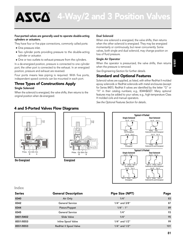
4 and 5-Ported Valves Flow Diagrams De-Energized Press. Cyl. A Cyl. B Exh. Energized Press. Cyl. A Cyl. B Exh. Series General Description Pipe Size (NPT) Page 8340 Air Only 1/4" 83 8342 General Service 1/4" and 3/8" 87 8344 Piston/Poppet 1/4" - 1" 89 8345 General Service 1/4" 93 8401/8402 Slide Valve 1/4" 95 8551/8553 Inline Spool Valve 1/4.
These valves close all ports in the off position to stop equipment in a locked position with air pressure holding it in place. They create two actions and have two exhaust ports, which allows you to control the speed of each action by attaching a flow control valve to each exhaust port. Also known as 4-way and 5/3 closed center valves.
Schematic Representation Of The Pneumatic Cylinder Valve System Scientific Diagram. Pneumatic 3 And 4 Way Solenoid Valve For Coil Design Namur Interface Actuator Control Ref Lucifer. Pneumatic Solenoid Valve 3 Way Normally Closed 12v 24v 110v 220v Ato Com. Schematic Of Experimental Setup1 Compressor 2 Three Way Valve 3 Scientific Diagram.
Description. The 4-Way Directional Valve block represents a directional control valve with four ports and three positions, or flow paths. The ports connect to what in a typical model are a hydraulic pump (port P), a storage tank (port T), and a double-acting actuator (ports A and B).Fluid can flow from the pump to the actuator via path P-A or P-B and from the actuator to the tank via path A-T.
In this video we take a look at how a reversing valve works in a heat pump, we explain the basic operation of a split system air-source heat pump as well as.
ASCO Piston Poppet Solenoid Valve 8344G001 120/60AC. $654.00 $549.36. The ASCO Series 8344 valves are packless, solenoid pilot controlled, heavy duty, 4-way valves with forged brass valve bodies and poppet type main discs. The main discs are power driven in both directions by line pressure.
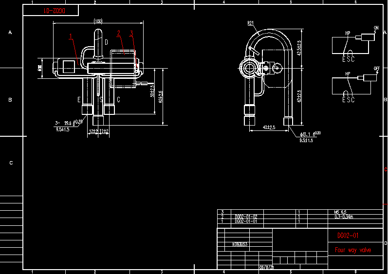
4-Way Reversing Valve with operating control used for heat pumps. This is called the 4-Way Reversing Valve, because it has four connections refrigerant pipes.Because the heat pump uses of reversible mechanical refrigeration cycle, such device is not required. Shown here, the heat pump cooling works like any cooling system when it is in cooling mode.










0 Response to "41 4 Way Valve Diagram"
Post a Comment