40 Msd 7al2 Wiring Diagram
Msd 7al 2 Wiring Diagram Collection. To identify which of the following diagrams fit your specific application, remove the distributor cap and. Note: Solid Core spark plug wires cannot be used with an MSD Ignition. Note: An MSD cannot be used on vehicles with CD ignitions or distributorless ignition. note: The MSD 7AL-3 will retard the ignition. Msd 7al 2 wiring diagram diagrams brianesser com library 7222 ignition control points to 3 16 stromoeko de u2022 ueosed thedelhipalace installation user manual pages chips schematic cd ignitions 7220 free shipping on orders over 99 at all data t6 plus not compatible with 16752175 best of two in point great install www toyskids co step 7al2.
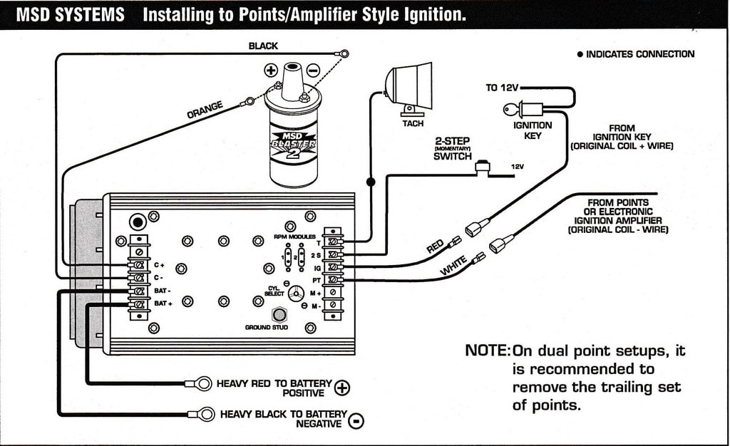
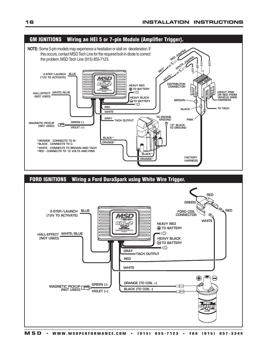
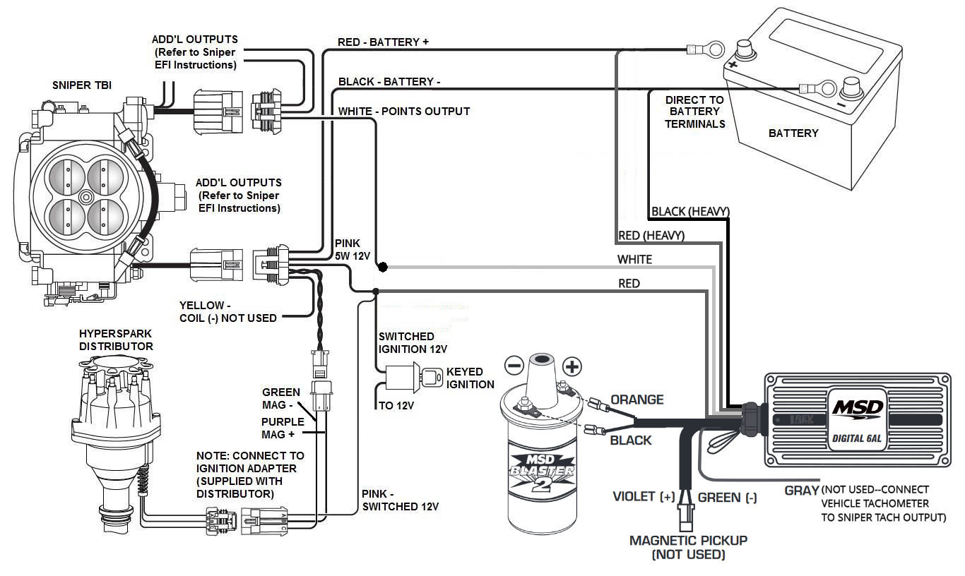
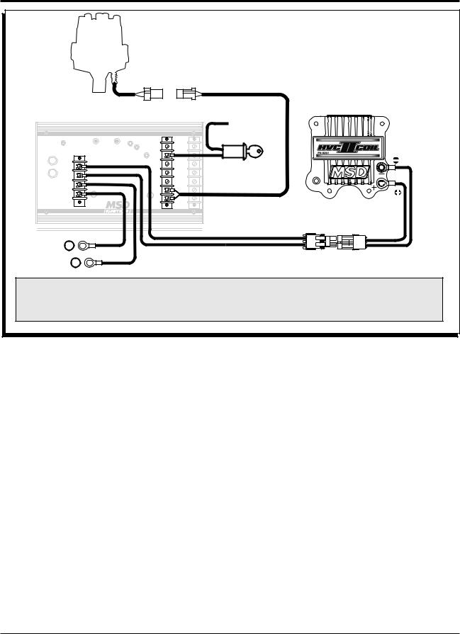
This is the correct wiring diagram from MSD, illustrating how to wire a 7AL2 ignition system triggered by a distributor with points. As you can see, it's not that difficult. Reworking a Stock Distributor to Trigger MSD Ignition Systems Part 4 10
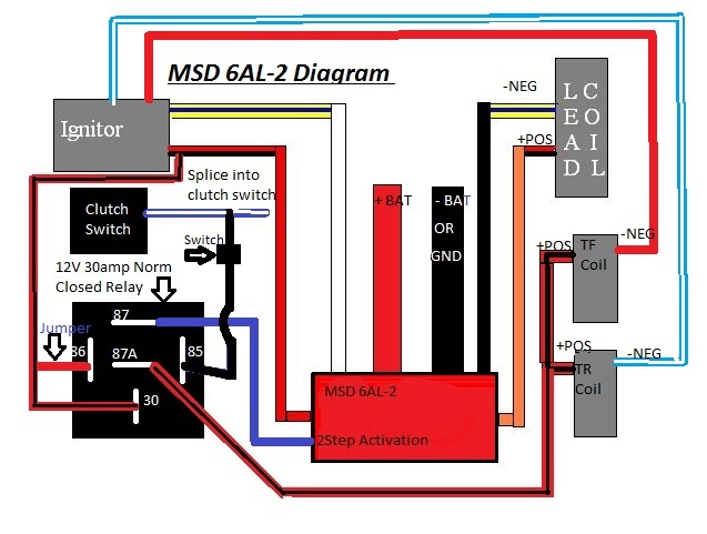
Msd 7al2 wiring diagram
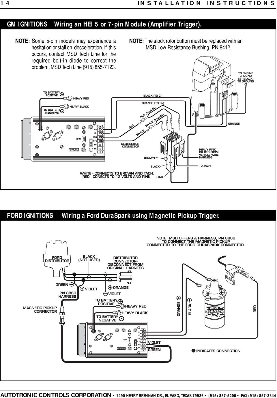
Note: Solid Core spark plug wires cannot be used with an MSD Ignition. Note: An MSD cannot be used on vehicles with CD ignitions or distributorless ignition systems. Parts Included: 1 - MSD 7AL-2 Plus Ignition 1 - White Wire 1 - Mag Pickup Extension Harness, PN 8860 1 - Red Wire 1 - Mag Pickup Adapter Harness, PN 8859 4 - Vibration Mounts and Hardware MSD 7al2 to unilite diagram? Post by Sirshredalot » Thu Apr 30, 2009 4:18 pm. Does anyone here know how to, or have a diagram of, how to wire an MSD 7al2 box up to a Mallory unilite distributor? Ive searched high and low, but cant seem to find a diagram. I just upgraded my set-up, so Im excited to see it run.. Nov 19, 2018 · Wowwee Dragonfly Wiring Diagram; Msd 7al2 To 8972 Wiring Diagram; Toro Ignition Switch Ssw2840 Wiring Diagram; Hyster 120xl Wiring Diagram 4.3; York Wiring Diagram H1dh030s06d; Kohler Marine Generator 9kw Wiring Diagram; 5.0 Mercruiser Starter Wiring Diagram; Tcs Decoder Wow Sound Installation Wiring Diagram; Venn Diagram Of Primary And.
Msd 7al2 wiring diagram. MPS Racing The 7AL-2 Plus Ignition is equipped with a 2-step rev control. The Ignition will accept two rpm. modules so two different rev limits can be set. One rev limit can be used for overrev protection while. the second limit can be activated on the starting line for a lower rpm limit to assist in staging and. for consistent holeshots. In this video I explain how to wire an MSD 8972 Multi-Step Retard box. We've gathered our favorite ideas for Msd 7al 2 Wiring Diagram 7220, Explore our list of popular images of Msd 7al 2 Wiring Diagram 7220 and Download Photos Collection with high resolution
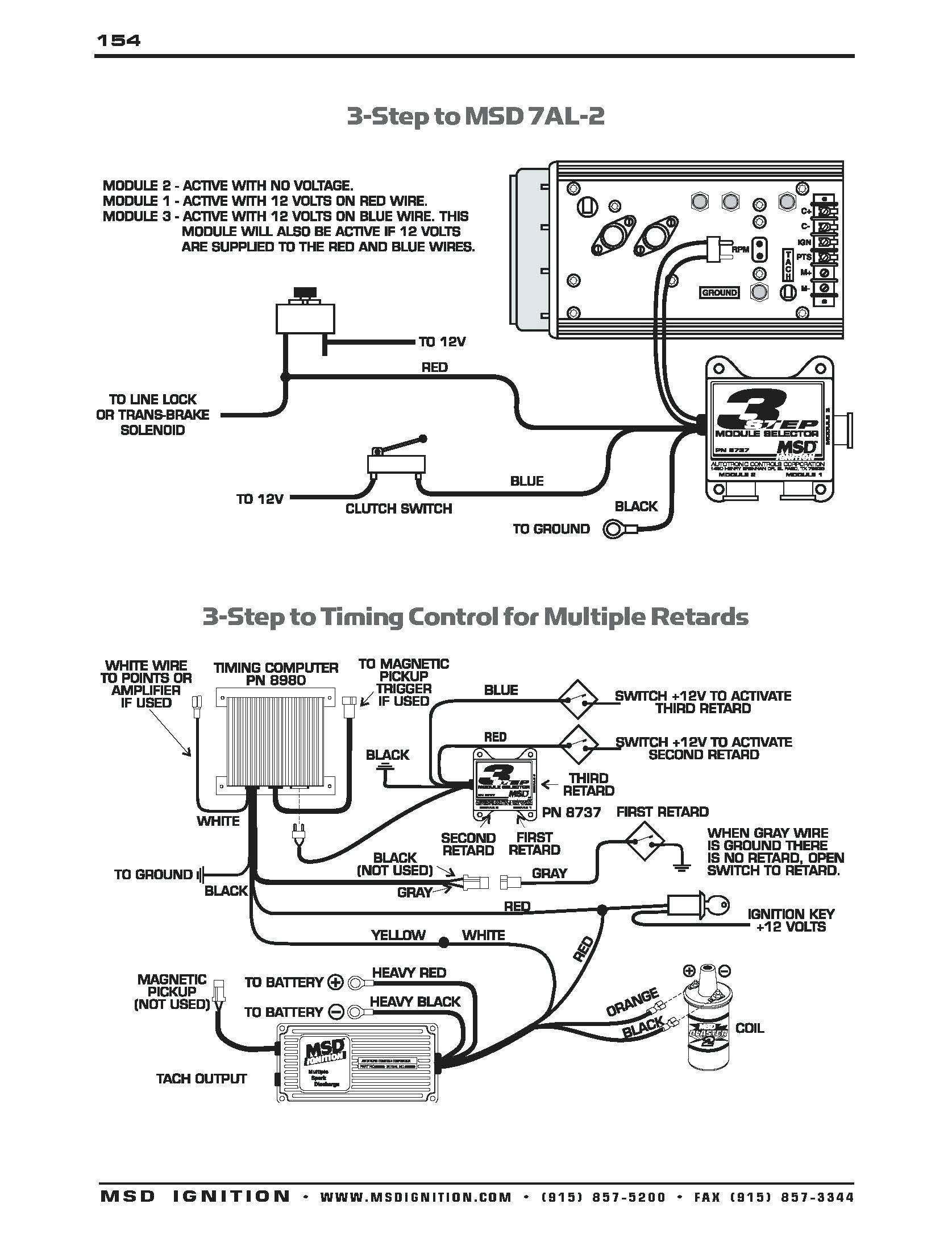
MSD Module Selectors Two Step, PN 8739 Three Step, PN 8737 Parts Included: 1 - Module Selector 4 - Mounting Screws Note: Do NOT use solid core spark plug wires with any MSD component. 1 - Parts Bag, Wiring Terminals The MSD Module Selectors provide the ability to switch between two or three different rpm or degree modules. Msd 7al Wiring Diagram - Schematics Wiring Diagrams • msd wiring diagrams brianesser com rh beta brianesser com msd 7al-2 wiring diagram msd 7al2. Msd Wiring Diagrams Brianesser Rh Beta Ford 6al Diagram Digital 7. Msd 7al 2 Wiring Diagram Schematic. Msd 7al 2 Wiring Diagram Find great deals for MSD Ignition Shop with confidence on eBay! As an example, we'll use a drag car with a Three Step Module Selector plugged into the rpm socket of a 7AL-2 Ignition. The different rpm modules are activated when 12 volts are applied to a corresponding wire. By connecting one wire to the line-lock circuit, one module will be activated during the burnout. This helps keep tire temperatures consistent. When the line-lock button is released. Msd 7Al2 Wiring Diagram Effectively read a electrical wiring diagram, one has to learn how typically the components within the system operate. For instance , when a module will be powered up and it also sends out the signal of half the voltage plus the technician will not know this, he'd think he offers a problem, as he would expect the 12V signal.
Wire Length: All of the wires of the MSD Ignition may be shortened as long as quality connectors are used or soldered in place. To lengthen the wires, use one size bigger gauge wire (10 gauge for the power leads and 16 gauge for the other wires) with the proper connections. All connections must be soldered and sealed. MSD Blaster Coil = 48000 volts MSD dist cap Dyna-Mod TFI = more dwell time for coil saturation. on the Challenger and MSD 7AL2, ProPower MSD coil MSD doesn't even make an 8 or a 10 ignition anymore They make several 7's, the 7AL2, 7AL3, and digital 7, then they make an 8 plus. i cant get it to run. m.. Dec 16, 2020 · FORD MUSTANG 1967. The following wiring diagrams illustrate numerous installations on different vehicles. Note: Solid Core spark plug wires cannot be used with an MSD Ignition. Note: An MSD cannot be used on vehicles with CD ignitions or distributorless ignition. note: The MSD 7AL-3 will retard the ignition timing approximately 4° compared to other MSD Ignitions. MSD 7al2 to unilite diagram? Post by Sirshredalot » Thu Apr 30, 2009 4:18 pm. Does anyone here know how to, or have a diagram of, how to wire an MSD 7al2 box up to a Mallory unilite distributor? Ive searched high and low, but cant seem to find a diagram. I just upgraded my set-up, so Im excited to see it run..
Note: Solid Core spark plug wires cannot be used with an MSD Ignition. Note: An MSD cannot be used on vehicles with CD ignitions or distributorless ignition systems. Parts Included: 1 - MSD 7AL-2 Plus Ignition 1 - White Wire 1 - Mag Pickup Extension Harness, PN 8860 1 - Red Wire 1 - Mag Pickup Adapter Harness, PN 8859 4 - Vibration Mounts and Hardware
Nov 19, 2018 · Wowwee Dragonfly Wiring Diagram; Msd 7al2 To 8972 Wiring Diagram; Toro Ignition Switch Ssw2840 Wiring Diagram; Hyster 120xl Wiring Diagram 4.3; York Wiring Diagram H1dh030s06d; Kohler Marine Generator 9kw Wiring Diagram; 5.0 Mercruiser Starter Wiring Diagram; Tcs Decoder Wow Sound Installation Wiring Diagram; Venn Diagram Of Primary And.
Figure 10 Wiring an MSD 10 PLUS with a Mag Pickup. INSTALLATION INSTRUCTIONS MSD IGNITION • www.msdignition • (915) 857-5200 • FAX (915) 857-3344 aCtIvatIng the retard through a nItrouS SolenoId The Retard can be activated at the same time as a nitrous solenoid. Connect the Gray wire to the
Msd 7al2 plus wiring diagram msd msd 7al 2 ignition control msd wonderful msd wiring diagram s electrical and wiring msd 7al2 plus wiring. Registering your product will help if there is ever a warranty issue with your product and helps the msd rd team create new products that you ask for.
Note: The MSD 7AL-3 will retard the ignition timing approximately 4° compared to other MSD Ignitions. After installation, the timing should always be checked and adjusted at idle and total timing. The following diagrams show the installation to a Mallory and an Accel BEI distributor. Figure 3 Primary Wiring to an Accel BEI Distributor.
Msd 7al 2 wiring diagram diagrams brianesser com library 7222 ignition control points to 3 16 stromoeko de u2022 ueosed thedelhipalace installation user manual pages chips schematic cd ignitions 7220 free shipping on orders over 99 at all data t6 plus not compatible with 16752175 best of two in point great install www toyskids co step 7al2.
MSD IGNITION • www.msdignition • (915) 857-5200 • FAX (915) 857-3344 oPtIoNAL WIRING This Wiring Section details the optional features of the MSD 7AL-3 and how to wire each system. StARt RetARD The Start Retard of the 7AL-3 is designed to ease starting on engines with locked timing, high compression and a lot of advance.
Msd 7Al2 Wiring Diagram Database. Electrical electrical wiring is a potentially dangerous task if done improperly. One should never attempt functioning on electrical electrical wiring without knowing typically the below tips & tricks followed simply by even the the majority of experienced electrician. wiring diagrams and tech notes - MPS Racing. 1 - MSD 7AL-2 Plus Ignition. 1 - White Wire. 1.
Hi I have, MSD 6AL #6425 MSD in car 2-step #8732 Trans brake Dedenbear delay box #RTD-7 Digi-set nitrous delay relay Single stage nitrous, 100 shot Delay box,Tbrake,2-step diagram help please. Back to Holley
MSD, Programmable Digital 7 Ignition Control MSD 6520 Digital 6 Plus Ignition Control Installation User Msd Digital 6al Wiring Diagram — UNTPIKAPPS MSD 8732 2 Step Rev Control for Digital 6AL Installation 8installation instructions m s d | MSD 6530 Digital 6425 MSD Digital 6AL Ignition Control available at MSD 7AL Box Instructions Video Book MSD Ignition | Camaro Forums at Z28 MSD Blaster GM.
MSD Module Selectors Two Step, PN 8739 Three Step, PN 8737 Parts Included: 1 - Module Selector 4 - Mounting Screws Note: Do NOT use solid core spark plug wires with any MSD component. 1 - Parts Bag, Wiring Terminals The MSD Module Selectors provide the ability to switch between two or three different rpm or degree modules.
MSD - For modified engines with a custom ignition curve, magnetic pickup, and that can be easily connected to a MSD ignition unit (5, 6AL, 7AL2/3, etc). Need to install diode incl. At Sparesbox, you can shop the complete Ignition Coils range from some of the world’s leading brands including PAT, Fuelmiser, NGK Spark Plugs, Goss and Tridon.
Hi guys, I have bought a power grid controller to replace my faulty 3 step control. But my 7AL2 only has one bank of connectors on the right hand side of the unit not a secondary bank on the left. Does someone have a connection diagram for my style 7AL-2 ? (part no. 7220, as pictured) Attached Images.
Apr 03, 1999 · Pertronix Billet Distributor – For modified engines with a custom ignition curve, magnetic pickup, and that can be easily connected to a MSD ignition unit (5, 6AL, 7AL2/3, etc). Magneto – For engines with no battery or source of electricity (generator/alternator).
MSD 7AL 2 Ignition PN Pirate4x4.Msd 7al 2 Wiring Diagram ~ welcome to our site, this is images about msd 7al 2 wiring diagram posted by Maria Rodriquez in Msd category on Nov 22, You can also find other images like wiring diagram, parts diagram, replacement parts, electrical diagram, repair manuals, engine diagram, engine scheme, wiring harness.
The following wiring diagrams illustrate numerous installations on different vehicles. Note: Solid Core spark plug wires cannot be used with an MSD Ignition. To identify which of the following diagrams fit your specific application, remove the.This is a used MSD 7AL2 box in perfect working condition. MSD 7AL2 ignition box with msd coil and rpm.
Figure 6 Primary Wiring to a GM HEI with a 4-Pin Module (Magnetic Pickup Trigger). GM HEI DISTRIBUTOR The 7AL-3 can be wired to the GM HEI Distributor. You must identify which module your distributor has to determine which wiring diagram to use. Count the number of pins or terminals on the module and follow the diagram for a 4-pin or 7-pin.
You'll recognize the 7AL-2 Plus Ignition Control, as its predecessor is the most popular ignition control used in drag racing. The "Plus" model updates the original 7AL-2 with improved internal components plus our engineers added a 2-Step Rev Control and a useful diagnostic LED. Racers will be happy to see that the updated components up the voltage output and spark energy! Over 40% more spark.
INSTALLATION INSTRUCTIONS 3 AUTOTRONIC CONTROLS CORPORATION • 1490 HENRY BRENNAN DR., EL PASO, TEXAS 79936 • (915) 857-5200 • FAX (915) 857-3344 WIRING The wire functions of the Timing Computer are: Black Connects to ground Red Connects to switched 12 volts White Connects to the points or amplifier output Yellow Connects to the White wire of the MSD.












0 Response to "40 Msd 7al2 Wiring Diagram"
Post a Comment