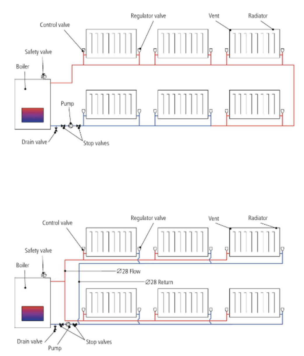
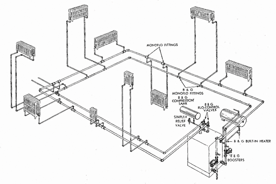
40 Monoflo Heating System Diagram
Kickspace Heater & Monoflow Tee. I have a question about monoflow tees (a.k.a. venturi tees or diversion tees). I have a one pipe series loop that supplies about 19' of baseboard. The total length of this run from the boiler loop and back is about 180' (3/4" PEX). Prior to the baseboard, the loop supplies a QuietOne 2006 kickspace heater. I have a single loop monoflo system. All convectors working fine except one in hallway. Vented it till hot water started coming out. the monoflo tee about 20" before it is hot and that convector is working fine. The one in question again which is about 20" away, has a nice hot pipe entering the convector, the return is ice cold, well actually the first 6" or so is hot probably the heat from.
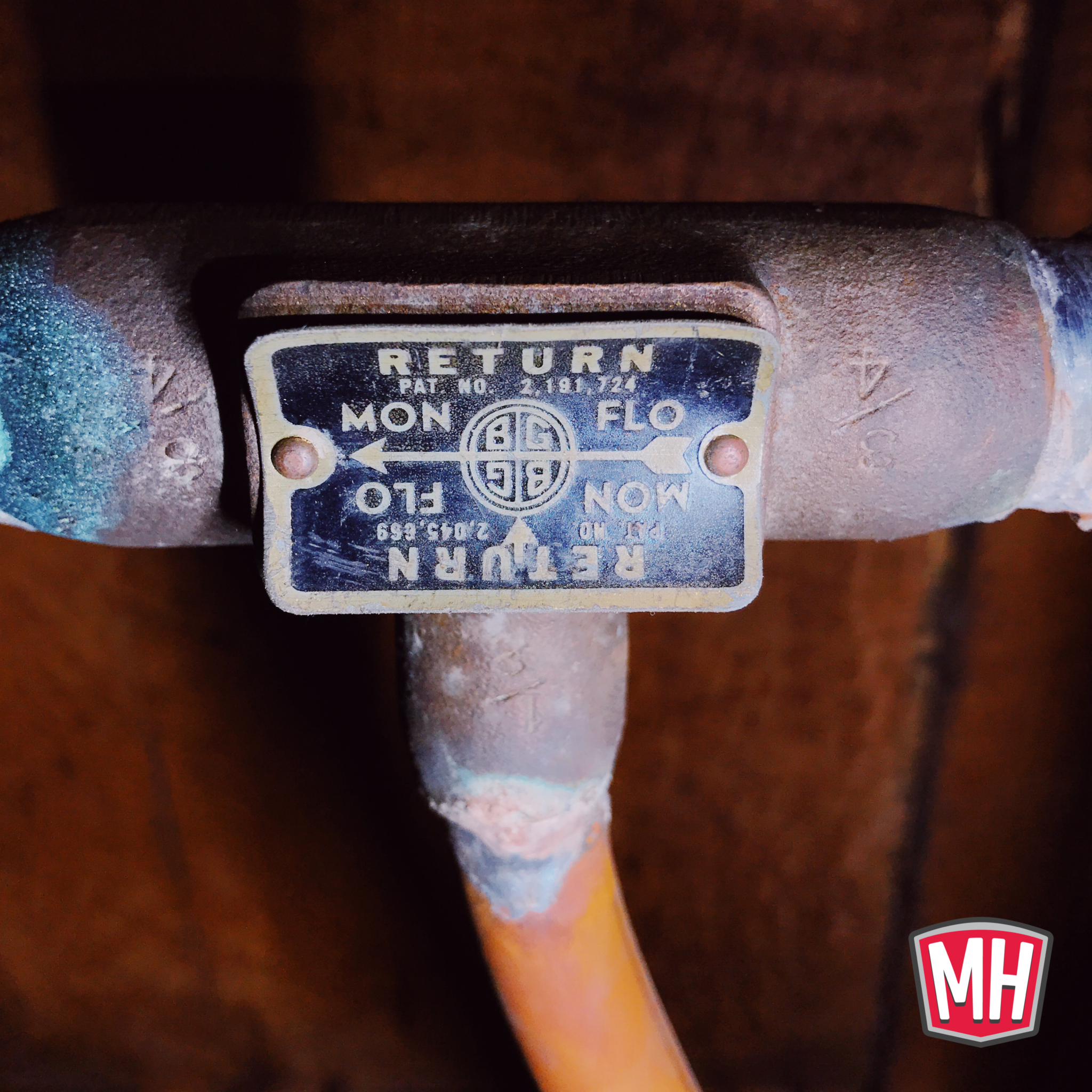
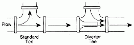
Monoflo Know-How From B&G. Sixty years ago, long before the invention of baseboard radiation, B&G Monoflo tees made one-pipe hot water heating possible. They continue to work in their simple way, diverting some hot water from the main, through the radiator and back again.
Monoflo heating system diagram
Heat, presented by the symbol Q and unit Joule, is chosen to be positive when heat flows into the system, and negative if heat flows out of the system (see Figure 17.1). Heat flow is a results of a temperature difference between two bodies, and the flow of heat is zero if T S = T E. monoflo system Venting the radiator we just shut down pump and bled from coin vent on radiator. Im sure its not air. And yes it is a monoflo system. Rest of the house heats great. This radiator is on the old back porch. The B&G Monoflo circuit operates on this principle. The Monoflo fitting provides a fixed orifice between the riser. systems use some variation of primary-secondary pumping technique.... primary circuit simply becomes one of heat conveyance to or from the secondary, while the secondary circuit serves the terminal heat transfer units.
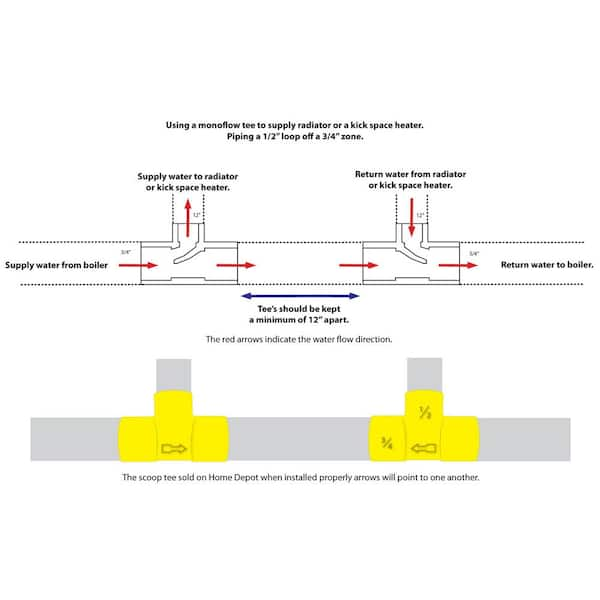
Monoflo heating system diagram. 1950's monoflow tee hydronic system. Ok, here goes, Doing a boiler change out, putting in a 4 section weil mclean gold, House was built in the 50's and has 2, 1 inch zones. half inch take offs to radiation, I suspect monoflow tee. Going to install diaphram expansion, and pump away with zone circs. Monoflo USA Spares & Service +1 713 466 7999 E-mail inquire@monoflo Mono China. 1.3 SYSTEM DESIGN AND INSTALLATION At the system design stage, consideration must be... Please refer to Wiring Diagram - Section 4, Page 1. IMMEDIATELY PRIOR TO INSTALLATION AND STARTING toe kick heater monoflo T explanation; Author: marklevinson1 (NJ) Hi, I remodeling my kitchen. I have hot water baseboard heat and I am replacing a baseboard heating unit with a toe kick heater as I am placing cabinets along that wall. I have worked up a diagram as to how I am going to proceed with the connections. The B&G Monoflo circuit operates on this principle. The Monoflo fitting provides a fixed orifice between the riser. systems use some variation of primary-secondary pumping technique.... primary circuit simply becomes one of heat conveyance to or from the secondary, while the secondary circuit serves the terminal heat transfer units.
Monoflo Know-How From B&G Sixty years ago, long before the invention of baseboard radiation, B&G Monoflo tees made one-pipe hot water heating possible. Today, you can find Monoflo tees by the tens of thousands in American heating systems. They continue to work in their simple way, diverting some hot water from the main, through theRead more Kickspace heaters are for use with forced hot water residential heating systems and consist of a copper tube, aluminum. Electrical connections are to be made to all units following the diagrams below. Choose the diagram that best... Our illustrations show a B&G monoflo (venturi) tee. The red ring on house only had one zone for 2 floors so i added a extra monoflow loop for 2nd flood and better heating control Copper Red Ring Monoflo Fittings let you use a single pipe to serve as both supply and return main. Features and Benefits Connect risers to the main, assuring proper division of water to each heating unit regardless of type and its position in the system. Recommended for most installations including cast iron non-ferrous baseboards, free-standingRead more
Boilers - Home Heating Steam and Hot Water Systems - Toe kick heater and monoflo tee's - Ok so let my attempt to get right into it. I have a parallel hot water system feeding 7 radiators. Im doing a This boiler water loop system is easy to zone but needs more piping and special monoflow tees for each separate circuit. Additionally, if not installed properly flow problems will occur in radiators and/or baseboards. It is really important if you have a monoflow system to consult a professional before making changes. This particular system was originally installed 60+ years ago and has Bell & Gossett Monoflo tees; a very innovative [for the time] invention by B&G that made one-pipe hot water heating systems possible. Why would we want to heat with one pipe? At the time steam systems were the norm for heating both large buildings and homes so the folks. —Add total equivalent feet of any heating unit (kickspace heater or fancoil). If given in Cv for the unit, use the by-pass chart to convert Cv to equivalent feet of tube. The total sum of the above equals the by-pass loop equivalent feet of tube. Take this total and enter the chart at the bottom.
Guide to Air Bleeder Valves on Heating Systems: Guide to Air Bleeder Valves on Heating Systems: Heating System Radiator, Baseboard, or Convector Air Bleeder Valve Troubleshooting & Repair Guide Hydronic heating air vents and air purge devices: types, where to buy How to diagnose and fix heating system noises & air in hot water heating system pipes Service Procedures to force air out of an air.
Refer to the Pressure Drop Diagram on page 31 for estimating the pressure drop through each radiator when using monoflow tees. Use the Pressure Drop Diagram on page 30 for a one-pipe system using diverter valves. Use the approximate flow rate through the radiator and flow setter valve setting to read off the pressure drop.
8. Stay away from open loop systems whenever possible. Closed loop systems are cleaner, quieter and have less operating problems than open loop systems. If you have to incorporate a non-pressurized component, such as an outdoor wood-fired furnace, separate it from the balance of the system with a heat exchanger. 9.
2.This requirement appears to be exacerbated by connecting a "loop" to the MonoFlo system. 3. Regardless of how you pipe the system, if there is not enough heat in the water to last till it flows through the final radiation, it will not heat. The water has to flow faster and/or start out hotter so it lasts till the end of the system. 4.
How to bleed heating system (remove air). A video on how to remove air from your heating system. I did a quick video on how to remove air from your hot wate...
Legend Monflow tees for Hydronic Heating Radiators and Fan Convector Systems. Image 2: See how to use 2 Legend Monoflow Tees for Hydronic Heating Systems. Legend Monflow tee for Hydronic Radiator and Fan Convector System. Generally you would use 2 mono flow tees when your radiator or fan convector is too far from the pump.
monoflo system Venting the radiator we just shut down pump and bled from coin vent on radiator. Im sure its not air. And yes it is a monoflo system. Rest of the house heats great. This radiator is on the old back porch.
Heat, presented by the symbol Q and unit Joule, is chosen to be positive when heat flows into the system, and negative if heat flows out of the system (see Figure 17.1). Heat flow is a results of a temperature difference between two bodies, and the flow of heat is zero if T S = T E.
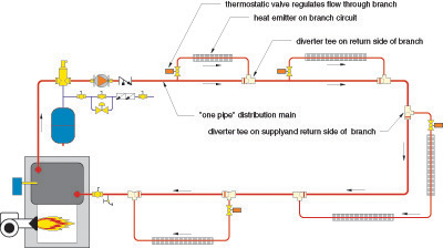
A Simulation Model for Diverter Tee Systems. This article shows how to apply the analytical concept of hydraulic resistance to analyze the hydraulic and thermal performance of systems using "diverter tees." Ask anyone who's been involved in hydronic heating for a few decades if they know what a "Monoflo® system".
Looking at a small reno heating job, homeowner wants to use cast-iron radiators left over from previous heating system. I'm to run the new lines and connect to rads, install boiler etc. I want to keep the piping design simple. Thinking about a series loop for each zone. Four zones, each has 4-7 rads. Haven't calculated GPM or head yet.
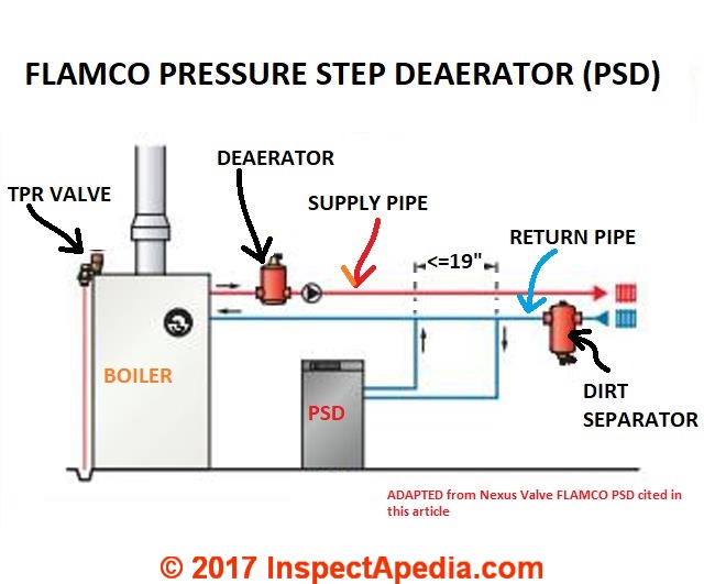
The heating boiler piping diagram at page top, courtesy of Raypak® shows the heating system circulator pump assembly (red in our sketch) on the return or inlet side of the heating boiler. By piping convention the triangle (which we surrounded in red for emphasis) points down, showing the direction of water flow.
Systems Diagram for Under Floor Radiant Heat; Water Heater; Reverse Return Heating System; Tank Type Water Heater; Plumbing; Boiler Loop; Radiator Piping; Monoflow Tees Diagram; Heating Systems; Floral Party Dresses For Women; Mykonos Greece Hotels; Honeydew Melon Cocktail; Chimichurri Sauce Recipe; Diy Vertical Herb Garden; Iphone Pinball Game.
The heat is pretty even throughout the house when boiler runs for a long time. also my piping is nothing like in those diagrams on the website. on the single loop in the basement it will branch off to a first floor rad and only that rad then back down into the loop. it is like that for 9 rads on the first floor.
HYDRONIC HEATING SYSTEMS: Hot water from a boiler or hot water heater is the medium for heat transfer in a hydronic system. Radiators are the most common source of heat transfer, but radiant loops are gaining popularity. Installation and materials costs have made aluminum finned copper tubing the most effective style.
Ive been doing a little research on monoflow systems. I get the jist of how they work, but I see no reason to use them over the simplier one pipe method. I have only seen one monoflow system in the field and I wasnt there to work on it. I have a call tommorow. A guy ran 3 floors of monoflow baseboard heat and its all on one zone.
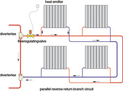
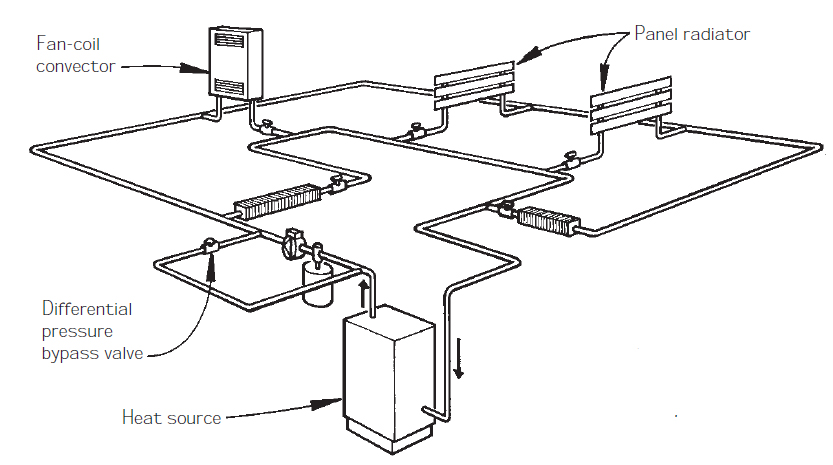
A “one-pipe system,” or “Monoflo system,” as it is sometimes called, is a distribution system that uses specialized tee fittings to divert a portion of the hot water through a branch piping path. If a manual or automatic control valve is placed in the branch piping path, the water flow through a given heat emitter can be fully controlled.
Piping layouts to avoid in hydronic systems. February 15, 2017 By John Siegenthaler. Einstein's definition of insanity was doing the same thing over and over and expecting different results. If that is true, there are some "insane" hydronic system designers in North America. They repeatedly cling to certain system piping configurations.
This diagram is typical of a "CLOSED" loop Hydronic heating system. Myson towel warmers and radiators are ideally suited for installation on a "CLOSED" system. Installation on a closed system prevents oxygenation (rusting) of the steel used in the manufacture of Myson radiators and some models of towel warmers. A closed system will, in most.












0 Response to "40 Monoflo Heating System Diagram"
Post a Comment