40 Make A Copy Of The Isothermal Transformation Diagram For An Iron-carbon Alloy
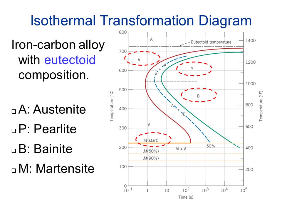
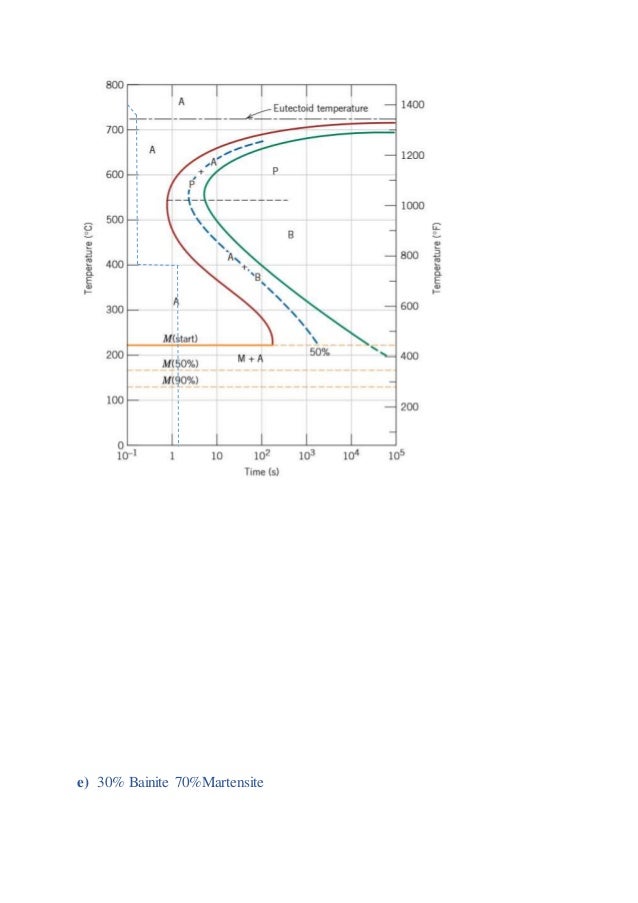
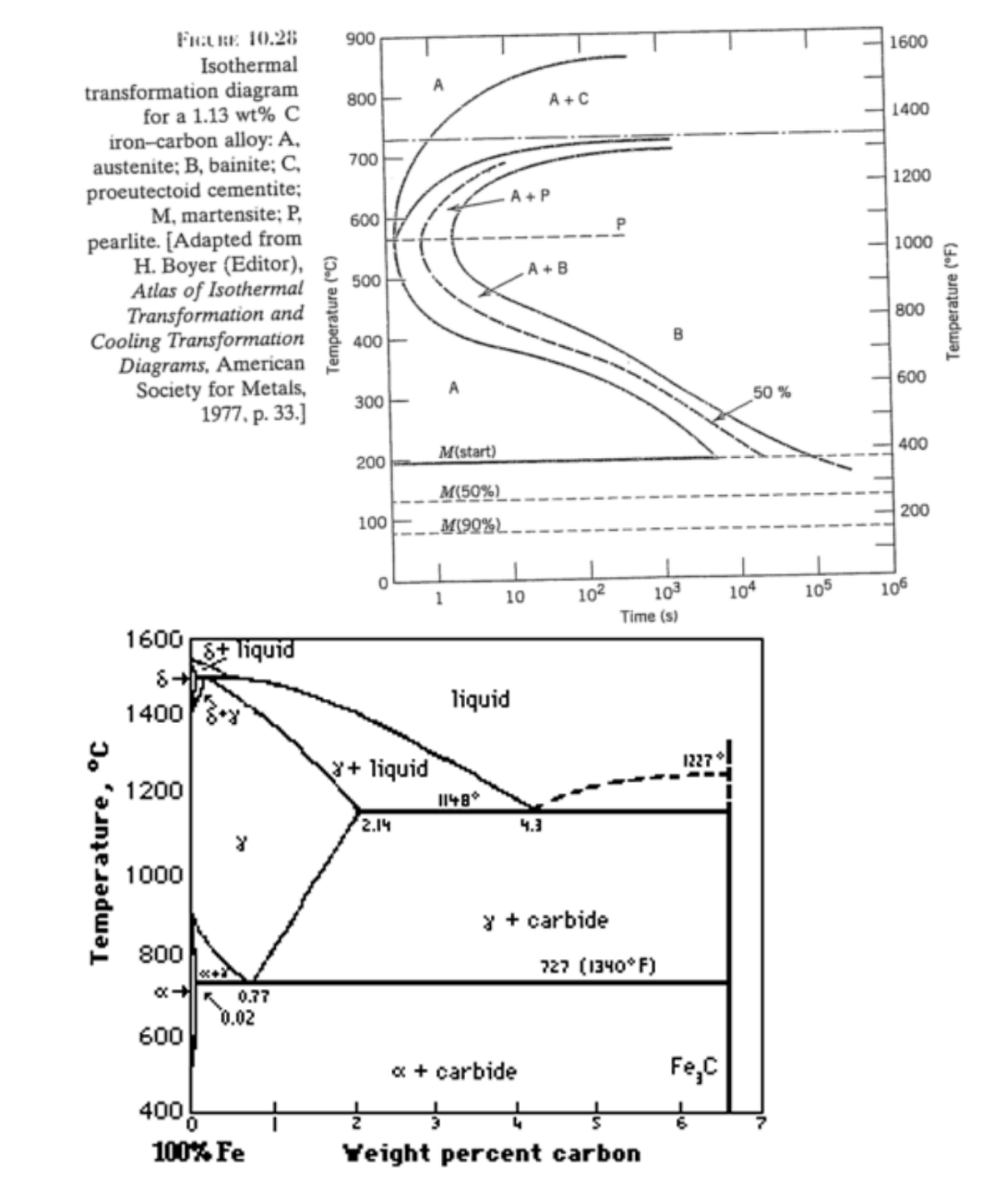
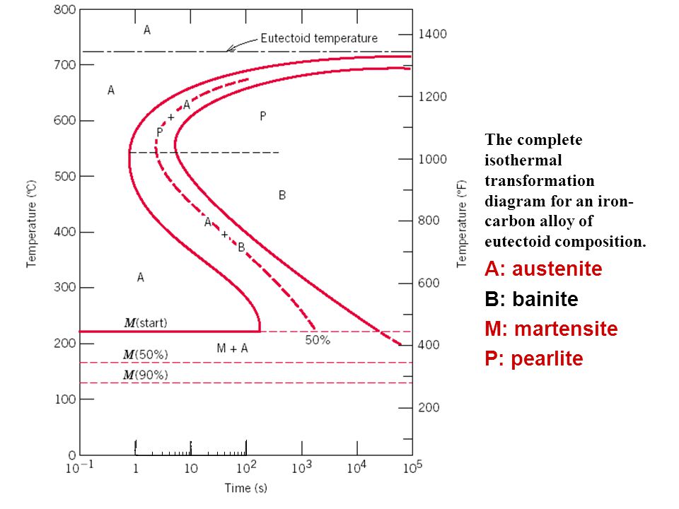
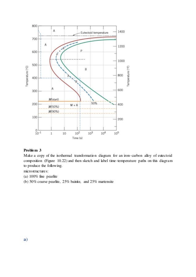
The complete isothermal transformation diagram for an iron-carbon alloy of eutectoid composition: A, austenite; B, bainite; M, martensite; P, pearlite. Martensite can only be formed with very rapid cooling rates Fig. 10.22 from Callister& Rethwisch, Materials Science & Engineering, An Introduction, 8 th ed., J. Wiley & Sons, 2010 7 Make a copy of the isothermal transformation diagram for a 1.13 wt% C iron-carbon alloy (Figure 10.39), and then on this diagram sketch and label time-temperature paths to produce the following microstructures: (a)6.2% proeutectoid cementite and 93.8% coarse pearlite (b)50% fine pearlite and 50% bainite (c) 100% martensite (d)100% tempered.
Question. Make a copy of the isothermal transformation diagram for a 1.13 wt% C iron–carbon alloy, and then on this diagram sketch and label time–temperature paths to produce the following microstructures: (a) 6.2% proeutectoid cementite and 93.8% coarse pearlite. (b) 50% fine pearlite and 50% bainite.
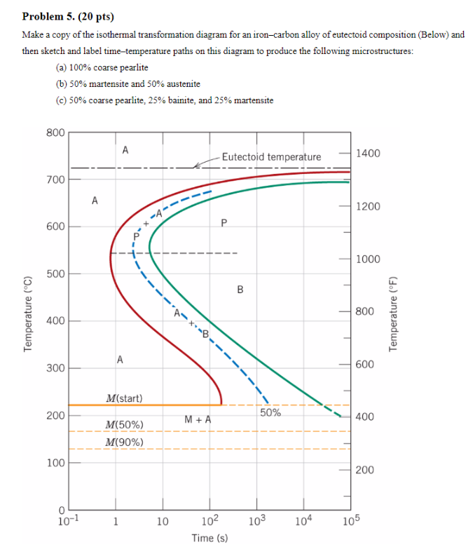
Make a copy of the isothermal transformation diagram for an iron-carbon alloy
toid iron-carbon alloy (0.76 wt% C) speci-mens that are first completely transformed to austenite, then cooled to room temperature at the following rates:(a) /s, (b) /s, (c) /s, and (d) /s. 10.24 Figure 10.40 shows the continuous cooling transformation diagram for a 0.35 wt% C iron-carbon alloy. Make a copy of this figure 10.21 For parts (a), (c), (d), (f), and (h) of Problem 10.20, determine the approximate percentages of the microconstituents that form. 10.22 Make a copy of the isothermal transformation diagram for a 0.45 wt% C iron-carbon alloy (Figure 10.39), and then sketch and label on this diagram the time-temperature paths to produce the following microstructures: (a) 42% proeutectoid ferrite and 58%. Make a copy of the isothermal transformation. diagram for an iron–carbon alloy of eutectoid. composition (Figure 10.22) and then sketch and. label time–temperature paths on this diagram to. produce the following microstructures: (a) 100% coarse pearlite. (b) 50% martensite and 50% austenite. (c) 50% coarse pearlite, 25% bainite, and 25%.
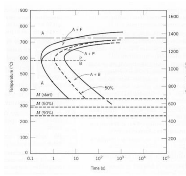
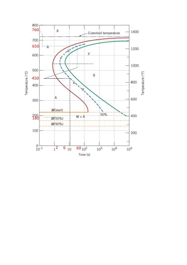
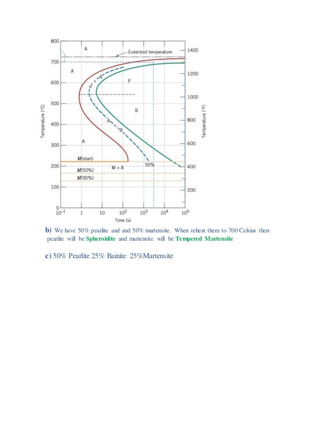
Make a copy of the isothermal transformation diagram for an iron-carbon alloy. Make a copy of the isothermal transformation. diagram for an iron–carbon alloy of eutectoid. composition (Figure 10.22) and then sketch and. label time–temperature paths on this diagram to. produce the following microstructures: (a) 100% coarse pearlite. (b) 50% martensite and 50% austenite. (c) 50% coarse pearlite, 25% bainite, and 25%. Make a copy of the isothermal transformation diagram for a $0.45 \mathrm{wt} \% \mathrm{C}$ iron-carbon alloy (Figure $10.39$ ), and then sketch and label on this diagram the time-temperature paths to produce the following microstructures: (a) $42 \%$ proeutectoid ferrite and $58 \%$ coarse pearlite (b) $50 \%$ fine pearlite and $50 \%$ bainite Step-by-step solution. 96% (46 ratings) for this solution. Step 1 of 3. Draw the isothermal transformation diagram for an iron-carbon alloy of eutectoid composition showing the given composition on it. Chapter 10, Problem 20QP is solved. Make a copy of the isothermal transformation diagram for an iron carbon alloy of eutectoid composition (Below) and then sketch and label time-temperature paths on this diagram to produce the following microstructures: (a) 100% coarse pearlite (b) 50% martensite and 50% austenite (c) 50% coarse pearlite, 25% bainite, and 25% martensite o 800 A.
Fig.4: Time temperature transformation (schematic) diagram for plain carbon eutectoid steel t 1 t 2 t 3 t 4 t 5 M F, Martensite finish temperature M 50, 50% Martensite M S, Martensite start temperature Metastable austenite +martensite Martensite e 0 100 e Log time Hardness A e1 T 2 T 1 50% T T 2 1 Pearlite Fine pearlite Upper bainite Lower bainite 7: Using the isothermal transformation diagram for a 1.13 wt% C steel alloy, determine the final microstructure (in terms of just the microconstituents present) of a small specimen that has been subjected to the following time-temperature treatments. In each case assume that the specimen begins at 920 oC and that it has been held at this temperature long enough to have achieved a complete. Phase Transformation NPTEL April 18th, 2019 - T T T diagram The relation between temperature and time for the formation of a phase is given by T T T or temp - time - transformation diagrams also known as isothermal transformation diagram A typical T T T diagram is shown below The phases formed on isothermal holding at a given temp Transcribed image text: 2. Make a copy of the isothermal transformation diagram for an iron-carbon alloy of eutectoid composition (Find TTT diagram from your slides) and then sketch and label time-temperature paths on this diagram to produce the following microstructures: (a) 100% coarse pearlite (b) 50% martensite and 50% austenite (c) 50% coarse pearlite, 25% bainite, and 25% martensite
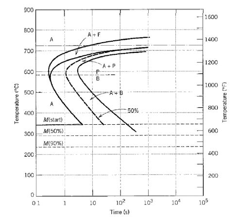
toid iron-carbon alloy (0.76 wt% C) speci-mens that are first completely transformed to austenite, then cooled to room temperature at the following rates:(a) /s, (b) /s, (c) /s, and (d) /s. 10.24 Figure 10.40 shows the continuous cooling transformation diagram for a 0.35 wt% C iron-carbon alloy. Make a copy of this figure Answer to Make a copy of the following accounts. Balance each account as appropriate. | SolutionInn Make a copy of the isothermal transformation diagram for an iron-carbon alloy of eutectoid composition (Figure 10.22 ) and then sketch and label time-temperature paths on this diagram to produce the following microstructures: a) $100 \%$ coarse pearlite b) $50 \%$ martensite and $50 \%$ austenite c) $50 \%$ coarse pearlite, $25 \%$ bainite, and Transformation Diagrams, American Society for Metals, 1977, p. 33.] 1600 1400 700 1200 600 1000 o soo 800 600 goo 400 200 100 102 103 Time (s) 104 IOS 200 106 11.10 Why must rivets of a 2017 aluminum alloy be refrigerated before they are used? 1022 Make a copy of the isothermal transforma- tion diagram for a 1.13 wt% C iron—carbon alloy.
University of Rhode Island
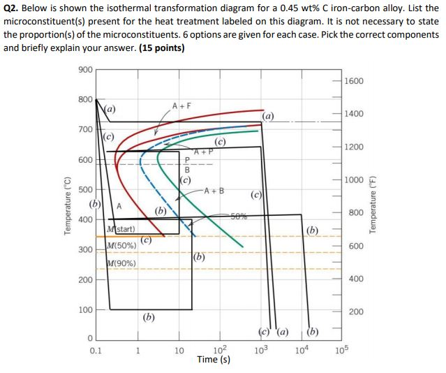
10.18 Below is shown an isothermal transformation diagram for a 0.45 wt% C iron-carbon alloy, with time-temperature paths that will produce (a) 42% proeutectoid ferrite and 58% coarse pearlite; (b) 50% fine pearlite and 50% bainite; (c) 100% martensite; and (d) 50% martensite and 50% austenite.
1019 using the isothermal transformation diagram for an iron carbon alloy of eutectoid composition. The thickness of the ferrite and cementite layers in pearlite is 81. Figure 1022 specify the nature of the final microstructure in terms of microconstituents present and. 6 Make A Copy Of The Isothermal Transformation Diagram For An Iron
Problem 3 Make a copy of the isothermal transformation diagram for an iron–carbon alloy of eutectoid composition (Figure 10.22) and then sketch and label time–temperature paths on this diagram to produce the following. microstructures: (a) 100% fine pearlite (b) 50% coarse pearlite, 25% bainite, and 25% martensite a) 8. b) 760 580 500 9.
Hence, the final microstructure is 100% tempered martensite. 22 Make a copy of the isothermal transformation diagram for a 0. 45 wt% C iron-carbon alloy (Figure 10. 39), and then sketch and label on this diagram the time-temperature paths to produce the following microstructures:(a) 42% proeutectoid ferrite and 58% coarse pearlite(b) 50% fine.
Make a copy of the isothermal transformation diagram for an iron-carbon alloy of eutectoid composition (Figure 10.22) and then sketch and label on this diagram a time-temperature path that will produce 100% fine pearlite. Rank the following iron-carbon alloys and associated microstructures from
Using the isothermal transformation diagram for an iron carbon alloy of eutectoid composition fi. 1018 using the isothermal transformation diagram for an ironcarbon alloy of eutectoid composition figure 1022 specify the nature of the final microstructure in terms of microconstituents present and approximate percentages of each of a small.
Using the isothermal transformation diagram for an iron-carbon alloy of eutectoid composition. The nature of the final microstructure of the specimen which is subjected to various heat treatment processes can be found out by use of figure 1022 complete isothermal transformation diagram for an iron carbon alloy of eutectoid composition.
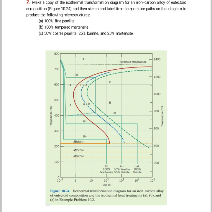
10.19 Make a copy of the isothermal transformation diagram for an iron–carbon alloy of eutectoid composition (Figure 10.22) and then sketch and label time–temperature paths on this diagram to produce the following microstructures: (a) 100% fine pearlite (b) 100% tempered martensite
Make a copy of the isothermal transformation diagram for a 0.45 wt% C iron-carbon alloy (Figure 10.39), and then sketch and label on this diagram the time-temperature paths to produce the following microstructures: (a) 42% proeutectoid ferrite and 58% coarse pearlite (b) 50% fine pearlite and 50% bainite (c) 100% martensite (d) 50%.
Need more help! Figure shows the continuous cooling transformation diagram for a 1.13 wt% C iron-carbon alloy. Make a copy of this figure and then sketch and label continuous cooling curves to yield the following microstructures: (a) Fine pearlite and proeutectoid cementite. (b) Martensite. (c) Martensite and proeutectoid cementite.
Using the isothermal transformation diagram for an iron-carbon alloy of eutectoid composition (Figure), specify the nature of the final microstructure (in terms of micro constituents present and approximate percentages of each) of a small specimen that has been subjected to the following time-temperature treatments.
10.22 Make a copy of the isothermal transformation diagram for a 0.45 wt% C iron-carbon alloy (Figure 10.39), and then sketch and label on this diagram the time-temperature paths to produce the following microstructures: (a) 42% proeutectoid ferrite and 58% coarse pearlite (b) 50% fine pearlite and 50% bainite (c) 100% martensite (d) 50%.
Transcribed image text: 10.20 Make a copy of the isothermal transformation diagram for an iron-carbon alloy of eutectoid composition (Figure 10.23) and then sketch and label time-temperature paths on this diagram to produce the following microstructures: (a) 100% fine pearlite (b) 100% tempered martensite (c) 25% coarse pearlite, 50% bainite, and 25% martensite 800 A Eutectold temperature 700.
10.21 For parts (a), (c), (d), (f), and (h) of Problem 10.20, determine the approximate percentages of the microconstituents that form. 10.22 Make a copy of the isothermal transformation diagram for a 0.45 wt% C iron-carbon alloy (Figure 10.39), and then sketch and label on this diagram the time-temperature paths to produce the following microstructures: (a) 42% proeutectoid ferrite and 58%.
Make a copy of the isothermal transformation diagram for an iron–carbon alloy of eutectoid composition provided overleaf and then sketch and label time–temperature paths on this diagram to produce the following microstructures: a) 25% martensite and 75% austenite b) 100% fine pearlite c) 25% pearlite, 25% bainite, 45% martensite, and 5%.


















0 Response to "40 Make A Copy Of The Isothermal Transformation Diagram For An Iron-carbon Alloy"
Post a Comment