40 D7 Tanabe Sugano Diagram
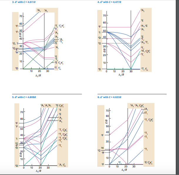
Tanabe-Sugano Diagrams. Tanabe-Sugano diagrams are used in coordination chemistry to predict electromagnetic absorptions of metal coordination compounds of tetrahedral and octahedral complexes. The analysis derived from the diagrams can also be compared to experimental spectroscopic data. Armed with spectroscopic data, an approximation to the. Tanabe-Sugano diagrams, the energy axis has units of E/B. The xaxis has - units of "o /B. Each TanabeSugano diagram is given for only one specific - B/C ratio (the best value). For example, the TanabeSugano diagram for d- 3 complexes is given for C=4.5 B. non-crossing rule: Terms of the same symmetry cannot cross and will 'repel' each.
a Tanabe-Sugano diagram. To make use of the Tanabe-Sugano diagrams provided in textbooks for all configurations, it would be expected that they should at least be able to cope with typical spectra for d3, d8 octahedral and d2, d7 tetrahedral systems. This is not the case. The diagrams presented are impractical, being far too small. To
D7 tanabe sugano diagram
Instructor: Alan F. Heyduk. Description: This course is an introduction to modern inorganic chemistry. Topics include principles of structure, bonding, and chemical reactivity with application to compounds of the main group and transition elements, including organometallic chemistry. Recorded on December 10, 2014. D7tanabe sugano diagram e b o b 4f 2g 2eg 2t1g 2a1g 2t2g 4p 4a 2g 4t 1g 4p 4t 2g 4t 1g 4f complexes with d4 d7 electron counts are special at small values of ob the diagram looks similar to the d2diagram at larger values of ob there is a break in the diagram leading to a. Tanabe sugano diagram java applets is a production of the interactive. d7 Tanabe-Sugano diagram. A Tanabe-Sugano diagram of the spin-allowed and some forbidden transitions for high spin octahedral d 7 complexes is given below. spin-allowed transitions (Δ/B' > 13.5) SOLID LINES 3 A 2g (P) ← 3 T 1g Green 3 T 1g (F) ← 3 T 1g Blue
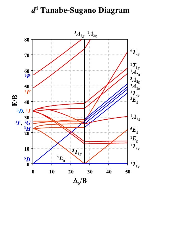
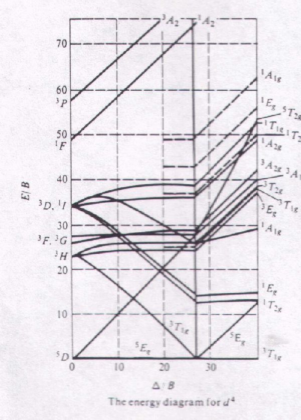
D7 tanabe sugano diagram. d2 Tanabe-Sugano Diagram 1A 1E 1g g 80 3A 2g 70 60 1T 1g 1T 1S 2g 3T 50 1g E/B 40 3T 2g 1A 1g 30 1G 20 1E 3P g 1D 1T 2g 10 3F 3T 0 1g ∆o/B 0 10 20 30 40 d3 Tanabe-Sugano Diagram 4T 2 1g A2g 80 70 2A 1g 4T 60 1g 50 4T 2g E/B 40 2F 2T 2g 30 2T 1g 20 2E 2G g 4P 10 4F 4A 0 2g ∆o/B 0 10 20 30 40 50 d4 Tanabe-Sugano Diagram 3A 1 2g A2 下着でつながるワコールのWebコミュニティ「MyWacoal(マイワコール)」のログインページです。 une nana cool|ウンナナクールの通販サイトです。ZOZOTOWNが運営。即日配送(一部地域)もご利用いただけます。 File:D7 Tanabe-Sugano diagram.png. Lecture 4 May Tanabe Sugano Diagrams A Tanabe-Sugano (TS) diagram plots the energy dependence of the various ligand field states (or terms) with field strength. The strength of the ligand field is defined by Dq, which is related to the octahedral crystal field splitting by 10Dq = ∆o.
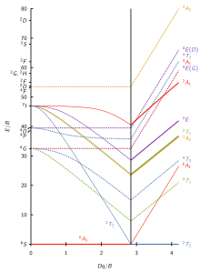
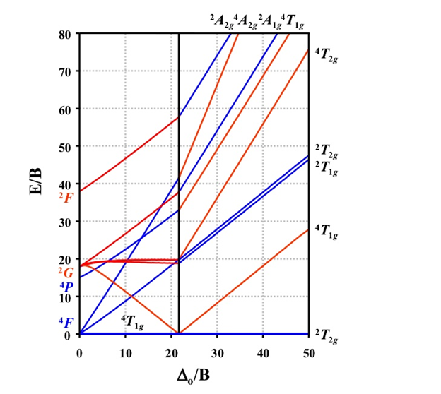
Using [V(H2O)6]3+and [Co(NH3)6]2+ as representative examples, UV-Vis data for V(III) is fit to the d2 Tanabe-Sugano diagram and known ligand field parameters... d7 Tanabe-Sugano Diagram. Captions. Summary. Description: English: The Tanabe-Sugano diagram for a d 7 transition metal ion. The energies are calculated using a Racah C = 4.5 B, and only selected states are depicted. The multiplicity of the ground state switches from a quartet to a doublet at the vertical line. Lecture 4 May 11: Tanabe Sugano Diagrams A Tanabe-Sugano (TS) diagram plots the energy dependence of the various ligand field states (or terms) with field strength. The strength of the ligand field is defined by Dq, which is related to the octahedral crystal field splitting by 10Dq = ∆o. The energy of the state is given by E. The section of "Orgel and Tanabe-Sugano Diagrams for Transition Metal Complexes (d1 - d9 States)" from the chapter entitled "Electronic Spectra of Transition Metal Complexes" covers the following topics: Orgel Diagrams: Orgel diagrams of d1, d9, d4, d6 systems; Orgel diagrams of d2, d8, d3, d7 systems; Orgel diagrams of d5 complexes.
Notes on d7 Tanabe-Sugano Diagram!The d 7 diagram, like all such diagrams for configurations that may be either high spin or low spin, has a perpendicular line near the middle marking the change in spin state. "To the left of the line (low field strength, high spin), the ground state is 4T 1, emerging from the free-ion 4F term. The baseline in the Tanabe-Sugano diagram represents the lowest energy or ground term state. The d 2 case (not many examples documented). The electronic spectrum of the V 3+ ion, where V(III) is doped into alumina (Al 2 O 3), shows three major peaks with frequencies of: ν1=17400 cm-1, ν2=25400 cm-1 and ν3=34500 cm-1. Certain Tanabe-Sugano diagrams (d4, d5, d6, and d7) also have a vertical line drawn at a specific Dq/B value, which corresponds with a discontinuity in the slopes of the excited states' energy levels. This pucker in the lines occurs when the spin pairing energy, P, is equal to the ligand field splitting energy, Dq. d7 Tanabe-Sugano diagram. A Tanabe-Sugano diagram of the spin-allowed and some forbidden transitions for high spin octahedral d 7 complexes is given below. spin-allowed transitions (Δ/B' > 13.5) SOLID LINES 3 A 2g (P) ← 3 T 1g Green 3 T 1g (F) ← 3 T 1g Blue
d7Tanabe-Sugano Diagram E / B ∆o/ B 4F 2G 2Eg 2T1g 2A1g 2T2g 4P 4A 2g 4T 1g ( 4P) 4T 2g 4T 1g ( 4F) Complexes with d4-d7 electron counts are special •at small values of ∆o/B the diagram looks similar to the d2diagram •at larger values of ∆o/B, there is a break in the diagram leading to a
The Orgel and Tanabe-Sugano diagram for d2-configuration can be used to estimate the value of crystal field splitting energy for these transition metal complexes. (a) (b) Figure 38. The (a) Orgel and (b) Tanabe-Sugano diagrams for d2 complexes in the octahedral crystal field. Consider the example of [V(H2O)6]3+. 1.
Transcribed image text: Refer to the Tanabe-Sugano diagram for a d7 complex in an octahedral field and answer the questions below: (a) What is the ground state free ion term (absence of a ligand field) for this configuration? (b) Draw this electron configuration. (c) What is the ground term for the d configuration in a weak Oh ligand field? (d) Draw this electron configuration.
Instructor: Alan F. Heyduk. Description: This course is an introduction to modern inorganic chemistry. Topics include principles of structure, bonding, and chemical reactivity with application to compounds of the main group and transition elements, including organometallic chemistry. Recorded on December 10, 2014.
Tanabe-Sugano diagrams. When simple formulas don't work or there are spin-forbidden transitions observed, then Tanabe-Sugano diagrams are used. d 2. d 3. d 4. d 5. d 6. d 7. d 8. An example. The spectrum of [Cr(NH 3) 6] 3+ is shown below. Find 10q and B. This is a d 3 complex. There are two approaches to finding B and 10Dq - use formulas and to.
D7tanabe sugano diagram e b o b 4f 2g 2eg 2t1g 2a1g 2t2g 4p 4a 2g 4t 1g 4p 4t 2g 4t 1g 4f complexes with d4 d7 electron counts are special at small values of ob the diagram looks similar to the d2diagram at larger values of ob there is a break in the diagram leading to a. Tanabe sugano diagram java applets is a production of the interactive.
2. The Tanabe Sugano diagram of the complex along with the absorption spectrum is shown below (figure 5). Figure 5: Tanabe-Sugano diagram and absorption spectrum for complexes with d7 configuration In this case the free ion term of ground state is 4F which splits into three states of same spin multiplicity namely 4T 1g, 4T 2g and 4A 2g. The.
A Tanabe-Sugano diagram of the spin-allowed and low-lying spin-forbidden transitions for octahedral d3 and tetrahedral d7 complexes is given below. Coordination Chemistry III: Tanabe-Sugano Diagrams and Charge Transfer. Chapter 11 extra material (to finish Chapter 11).
d2Tanabe-Sugano Diagram E / B ∆o/ B 3F 3P 3T 1g (3P) 3A 1g 3T 2g (3F) 3T 1g ~15B ~∆o ~∆o E1 E2 E3 E is the energy of the excited state relative to the ground state B is the Racah parameter for e–-e–repulsion The example on page 427 of your text shows how to use this chart to fit the experimental data (E1, E2, and E3) for [V(OH2)6]3+to.
2 • Tanabe-Sugano diagrams have been calculated for d the cases of all ligand field strengths for all octahedral dn-metal complex configurations. • The diagrams allow for estimation of a complete set of parameters included in the calculations: i) the (apparent) electron repulsion parameter B', ii) D, iii) transition frequencies. 52
A step-by-step tutorial on assigning the transitions in the UV-vis spectrum of a d7 system using a Tanabe-Sugano Diagram.
Tanabe Sugano Diagram Of D 3 Electronic Configuration. D2tanabe sugano diagram e b ∆o b 3f 3p 3t 1g (3p) 3a 1g 3t 2g (3f) 3t 1g ~15b ~∆o ~∆o e1 e2 e3 e is the energy of the excited state relative to the ground state b is the racah parameter for e- e-repulsion the example on page 427 of your text shows how to use this chart to fit the experimental data (e1, e2, and e3) for [v(oh2)6]3 to.
Tanabe sugano diagram 1. PRESENTED BY: Khondaker Afrina Hoque. ID-1114015, Reg:900048 Department of chemistry. Comilla university 2/26/2019 1 2. TANABE-SUGANO DIAGRAM 2/26/2019 2 3. Introduction Background: • Yukito Tanabe and satoru sugano- " On the Absorption spectra of complex ions"-1954.
Limitations of MO Diagrams The problem: orbital energy diagrams ignore inter-electron repulsion, i.e., several states comprise the (t 2g)1(e g) 1 configuration,
d7 Tanabe-Sugano Diagram 2A 4A 2A 4T 2g 2g 1g 1g 80 4T 2g 70 60 50 2T 2g 2T 1g E/B 40 2F 30 4T 1g 20 2G 4P 10 4F 4T 1g 2T 0 2g 0 10 20 30 40 50 ∆o/B 7. d8 Tanabe-Sugano Diagram 1A 1T 3T 1g 2g 1g 80 1E g 70 1T 60 1T 1g 1S 2g 3T 50 1g E/B 3T 40 2g 1A 30 1g 1G 20 1E 3P g 1D 10 3F 3A 0 2g 0 10 20 30 40 ∆o/B.
A step by step tutorial on assigning the transitions in the uv vis spectrum of a d7 system using a tanabe sugano diagram. D7tanabe sugano diagram e b ∆o b 4f 2g 2eg 2t1g 2a1g 2t2g 4p 4a2g 4t1g (4p) 4t2g 4t1g (4f) small ∆o high spin large ∆o low spin complexes with d4 d7 electron counts are special •at small values of ∆o b the diagram looks similar to the d2diagram •at larger values.
D7 Tanabe Sugano Diagram; 1997 Sea Ray Sundancer 270 Bilge Pump Wiring Diagram; Kohler Niedecken Diagram; Fill Rite Fr1200c Control Wiring Diagram; Wiring Diagram For 2013 48 Volt Ez Go Solenoid; Epson 1430 Wiring Diagram; Dimarzio Two Humbuckers With 3-way Center Coil-split Selector Switch Wiring Diagram (2rokzeu) Kawasaki Prairie 360 Carb Diagram
Certain Tanabe–Sugano diagrams (d 4, d 5, d 6, and d 7) also have a vertical line drawn at a specific Dq/B value, which is accompanied by a discontinuity in the slopes of the excited states' energy levels.This pucker in the lines occurs when the identity of the ground state changes, shown in the diagram below. The left depicts the relative energies of the d 7 ion states as functions of.








0 Response to "40 D7 Tanabe Sugano Diagram"
Post a Comment