40 Aem 35 8460 Wiring Diagram
Aem Wideband Wiring Diagram / Aem 35 8460 Wiring Diagram / The serial cable also needs a chassis ground. Januari 09, 2021 Type of wiring diagram wiring diagram vs schematic diagram how to read a wiring diagram: To bridge these i followed the method (just the method use the wires and resistors i tell you) of this gentleman. Electrical Wiring; Interconnect Cables; AEM Electronics 35-3400 AEM Electronics 35-3400 - AEM Electronics Replacement Wideband UEGO Controller Air/Fuel Ratio Gauge Components. Part Number: AVM-35-3400
Figure The wiring diagram for all standard MX actuators is shown on page 9... Limitorque is the only electronic valve actuator manufacturer that provides the user with. Limitorque L Installation, Operation and Maintenance FCD LMENIM A4 - 06/ .. Refer to the wiring diagram supplied with your specific actuator.
Aem 35 8460 wiring diagram
Aem 35 8460 Wiring Diagram. 10.04.2019 10.04.2019 6 Comments on Aem 35 8460 Wiring Diagram. AEM - Product Installation Manuals. AEM UEGO Gauge Air Fuel Ratio Controller Installation Manual AEM CDI Coil Setup Diagram. I pulled the wiring harness off the gauge and the pins fell off the connector. until the O2 #1 Volts display in AEMPro reads 2.35 volts. When connecting to AEM's Series2 EMS, Page 8 1. Unplug the O2 Sensor from the 30-4110 Gauge. 2. Open up the O2 Calibration Setup Wizard by navigating to Wizards -> Setup Wizard -> Sensor: O2 #1 (AFR) 3.. Effectively read a wiring diagram, one has to know how typically the components inside the method operate. For example , when a module will be powered up and it sends out a new signal of fifty percent the voltage plus the technician does not know this, he'd think he offers a challenge, as this individual would expect a new 12V signal.
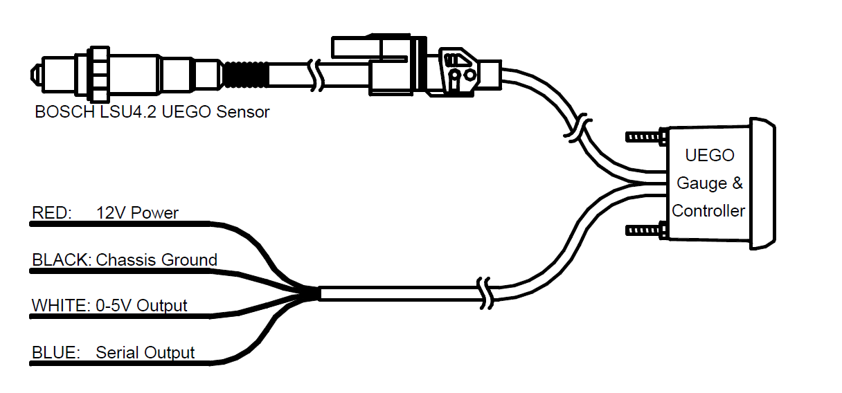
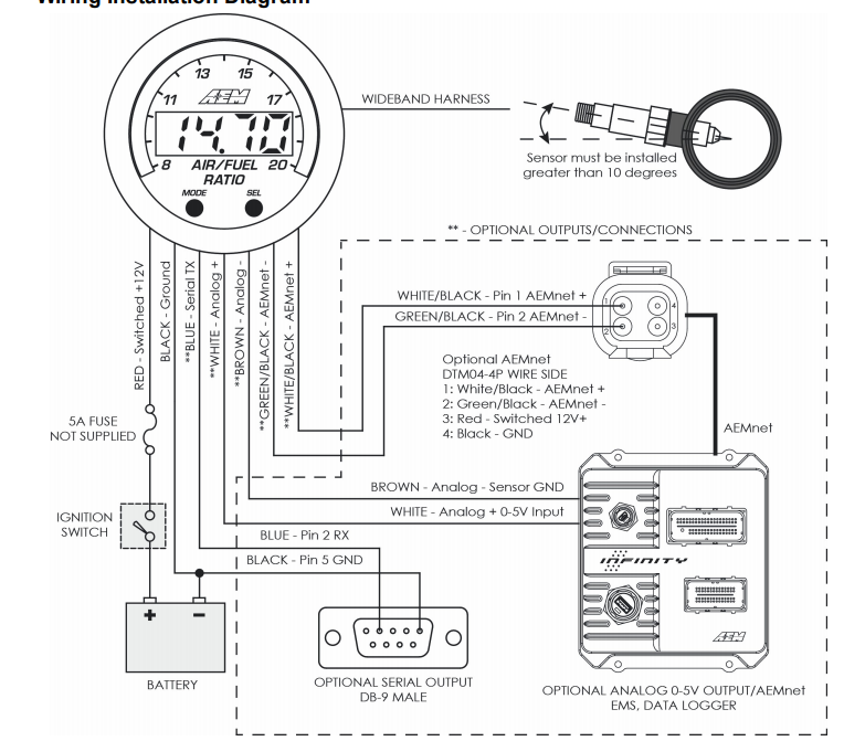
Aem 35 8460 wiring diagram. When connecting to AEM's EMS, make sure to verify that the O2 #1 Gain option is set so the voltage from the O2 #1 Volts parameter matches the voltage input at the EMS from the O2 sensor. An easy way to do this is to disconnect the UEGO sensor from the UEGO gauge. When in this state, the UEGO gauge will output 2.35 volts. You can then Aem 35 8460 Wiring Diagram. Wiring Diagram 81 views. Kicker Pt250 Wiring Diagram. Wiring Diagram 520 views. Brake Controller Wiring Diagram. Wiring Diagram 177 views. 7 Way Rv Blade Wiring Diagram. Wiring Diagram 259 views. Ssr Pit Bike Wiring Diagram. Wiring Diagram 206 views. Search for: Recent Posts. Through the thousands of pictures online regarding aem air fuel gauge wiring diagram, we picks the very best collections using ideal quality exclusively for you all, and now this pictures is usually among photographs choices in this very best photos gallery about Aem Air Fuel Gauge Wiring Diagram.I'm hoping you will like it. This specific picture (Aem Afr Gauge Wiring Diagram Aem 35-8460. Figure 1. Wiring Schematic AEM Gauge-Type UEGO Controller Parts 1 x 35-5130(B/W) UEGO Gauge Assembly 1 x 30-2001 UEGO Sensor 1 x 35-8535 Install Kit (O2 Bung with 6 Butt Connectors) 1 x 10-5130 Installation Instructions 1 x 35-3411 8-Pin Power Harness 1 x 35-3400 6-Pin Sensor Harness 1 x 35-8529S Silver Bezel
until the O2 #1 Volts display in AEMPro reads 2.35 volts. When connecting to AEM's Series2 EMS, Page 8 1. Unplug the O2 Sensor from the 30-4110 Gauge. 2. Open up the O2 Calibration Setup Wizard by navigating to Wizards -> Setup Wizard -> Sensor: O2 #1 (AFR) 3.. Come to find out, there something with the 0-5v output of the aem that the eld cant read. It wont read below 1.7v, so i had to unsolder two resistors on the board, c300 c301. Now it works great. Now, i dont know what to believe. When in boost the aem GAUGE will display mid 10s afr, but the built in wideband will read mid to high 12s. An easy way to do this is to disconnect the UEGO sensor from the UEGO gauge. When in this state, the UEGO gauge will output 2.35 volts. You can then adjust the O2 #1 Gain until the O2 #1 Volts display in AEMPro reads 2.35 volts. When connecting to AEM's Series2 EMS, 1. Unplug the O2 Sensor from the 30-4110 Gauge. 2. AEM Air Intake on a 2011-2014 Hyundai Sonata / 2011-2015 Kia Optima 2.4L Episode 1: Install AEM Electric watt meter secret control function Instruction Manual Aem AEM Performance Electronics 2205 126th Street Unit A, Hawthorne, CA. 90250 Phone: (310) 484-2322
Effectively read a wiring diagram, one has to know how typically the components inside the method operate. For example , when a module will be powered up and it sends out a new signal of fifty percent the voltage plus the technician does not know this, he'd think he offers a challenge, as this individual would expect a new 12V signal. Aem 35 8460 Wiring Diagram. Wiring Diagram 66 views. Search for: Recent Posts. 1 2007 Honda Pilot Radio Wiring Diagram; 2 Car Keyless Entry Wiring Diagram; 3 Buck Stove 27000 Wiring Diagram; 4 2004 Hyundai Santa Fe Wiring Diagram; 5 Ford F250 Wiring Diagram Online; Categories. Wiring Diagram; CAMERA GP Description. Description: Cat camera provides a 115° horizontal view, to give the equipment operator an unobstructed view from the rear of the vehicle. Cat service and replacement parts allow easy field service of heavy-duty equipment. Quality you expect for your rugged work environment. Description : Aem Afr Gauge Wiring Diagram Aem 35-8460 Wiring Diagram Wiring intended for Aem Air Fuel Gauge Wiring Diagram, image size 643 X 561 px. Description : Aem Air Fuel Gauge Wiring Diagram Aem Wideband Wiring Diagram with Aem Air Fuel Gauge Wiring Diagram, image size 750 X 338 px. Actually, we also have been remarked that aem air fuel.
AEM Performance Electronics Support - Instructions. If you are searching for product-specific instructions enter the Part Number (located on the UPC label of your box, or on the product page of our website). If you are searching for a Supported Application for a CD Carbon Dash or Infinity ECU, search using the manufacturer name (for example.
Wiring Diagram - Everything You Need to Know About Wiring Diagram Wiring Diagram - Read and Draw Wiring Diagrams Free wiring diagrams for your car or truck. Including lighting, engine, stereo, hvac wiring diagrams. Get your Free Automotive Wiring Diagrams Sent right to you
Wiring Schematic. AEM Gauge -Type UEGO Controller Parts. 1 x (B/W) UEGO Gauge Assembly. Aem 35 Wiring Diagram. welcome to my blog here I will show you a little more what you are looking for Aem 35 Wiring Diagram below there are.Find best value and selection for your AEM Wideband O2 Air Fuel UEGO Gauge Only 35 Tested Works Great search on eBay.
Aem Wideband 35-8460 Wiring Diagram. Print the wiring diagram off in addition to use highlighters to be able to trace the circuit. When you make use of your finger or perhaps follow the circuit with your eyes, it's easy to mistrace the circuit. 1 trick that I actually use is to print out exactly the same wiring plan off twice.
This particular photograph (Aem Afr Gauge Wiring Diagram Aem 35-8460 Wiring Diagram Wiring intended for Aem Air Fuel Gauge Wiring Diagram) previously mentioned is usually labelled together with: aem, air, diagram,. Put up by means of Tops Stars Team with May, 3 2014.
Wiring In Gauges And Aem Wideband How To Version Of. AFR Gauge. AEM 35-8460. Gauge Wiring Diagram. Boost Control Solenoid Diagram. Connection ECU. Map Sensor. Series 1. Bosch 4 Wire O2 Sensor Wiring Diagram.
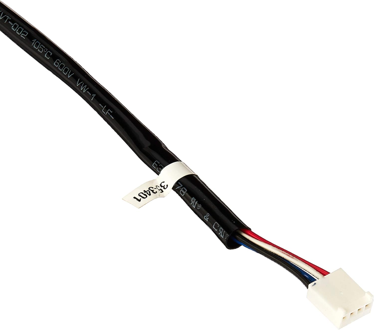
AEM 35-8460 wiring. I bought a aem wideband from a buddy its a 35-8460 need some help on wiring this thing has a 4 pin harness with a looped blue wire then a white pink and purple not familiar with the set up please help me out here thanks. Knows Some Stuff About 240's!
Aem 35 8460 Wiring Diagram. 10.04.2019 10.04.2019 6 Comments on Aem 35 8460 Wiring Diagram. AEM - Product Installation Manuals. AEM UEGO Gauge Air Fuel Ratio Controller Installation Manual AEM CDI Coil Setup Diagram. I pulled the wiring harness off the gauge and the pins fell off the connector.
See details. - AEM Digital 35-8460 air/fuel ratio gauge (G119836-1 RO LOC BY-80F) Watch. Sold by rjjewelry4 ( 28394) 100.0% Positive feedback Contact seller. Help.
Aem Wideband 35 8460 Wiring Diagram. abby.kulas July 22, 2021 Templates No Comments. 21 posts related to Aem Wideband 35 8460 Wiring Diagram. Aem Wideband Output Voltage. 4l60e Transmission Wiring 4l60 Wiring Diagram. Wiring Diagram App Mac. Cat C15 70 Pin Ecm Wiring Diagram. Yfz 450 Wiring Diagram.
Aem Wideband Wiring Diagram / Aem 35 8460 Wiring Diagram / The serial cable also needs a chassis ground.. Type of wiring diagram wiring diagram vs schematic diagram how to read a wiring diagram: To bridge these i followed the method (just the method use the wires and resistors i tell you) of this gentleman.
UEGO gauge. When in this state, the UEGO gauge will output 2.35 volts. You can then adjust the O2 #1 Gain until the O2 #1 Volts display in AEMPro reads 2.35 volts. When connecting to a third party EFI system, the AEM UEGO gauge's WHITE Analog Output wire shall be connected to the analog O2 sensor input of that system. Consult
Aem 35 8460 Wiring Diagram Sep.. Feb 11, 2016 — Manual. The 52mm (2-1/16”) AEM X-Series Universal Exhaust Gas Oxygen... 35-2004. SENSOR, WIDEBAND UEGO BOSCH LSU 4.9 ... are located on the face of the gauge for configuration; refer to the diagram below.. Jan 22, 2007 — like to hook up the aem wideband to my mpvi (or however you spell ...
AEM offers a variety of aftermarket wiring harnesses from plug and play applications to programmable options. Check out our performance products today!













0 Response to "40 Aem 35 8460 Wiring Diagram"
Post a Comment