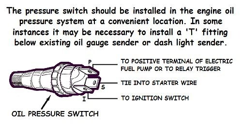
39 Fuel Pump Oil Pressure Switch Diagram
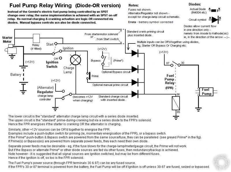
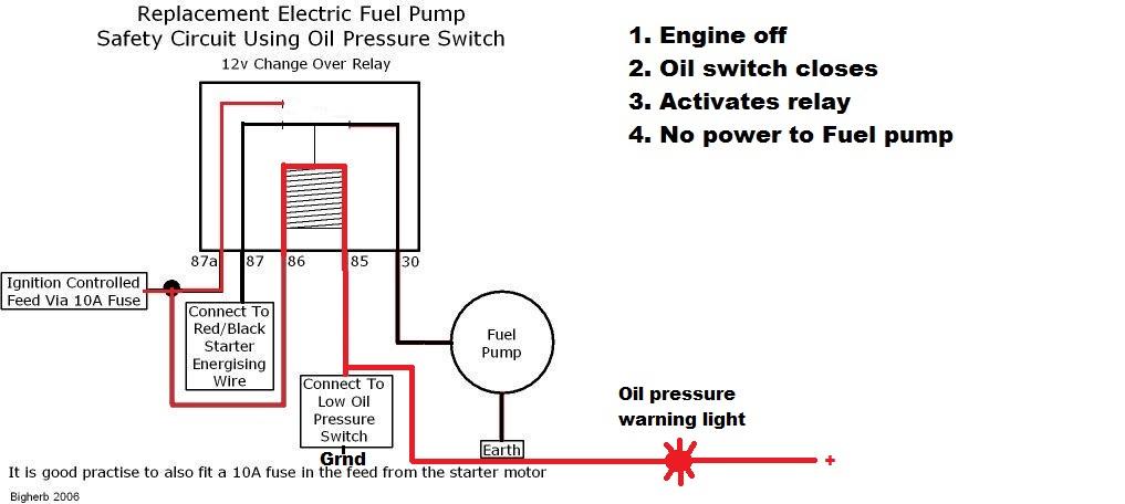
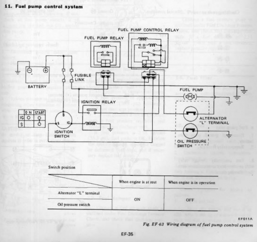
If the fuel pump relay should fail the vehicle will still start once enough oil pressure is created to close the contacts. This is why you may get extended cranking on initial startup because the fuel pump relay is not working but the closing of the oil pressure switch ( once oil pressure is reached during cranking) will allow fuel pump operation. Relay, fuel pump, oil pressure switch - Hi everyone. Got a weird technical issue with a friend. He has an aftermarket fuel pump and harness along with an oil pressure switch. Relay is SPDT and wired accordingly. 30 is 12v 87 is power to pump 85 is trigger to oil pressure safety switch 86 is ground
Connect the fuel pump (RED lead) to the terminal marked "C".. using the wiring diagram (on back) as a guide. 1. Disconnect the ground cable from the battery. 2. Remove the original equipment oil pressure switch and retain. 3. Screw a 1/8" pipe nipple into the hole from which the pressure switch was removed. Use any suitable thread...
Fuel pump oil pressure switch diagram
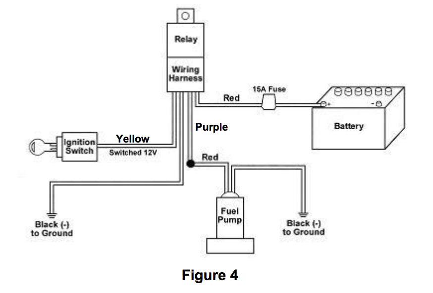
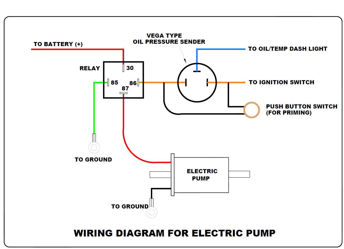
Basic Safe Electric Fuel Pump Wiring Diagram This is the basic wiring diagram for SAFE electric fuel pump wiring. The diagram is color coded per circuit and only a few things may need to be said. Fuel pump wiring for the RED circuit is generally going to carry a much higher current than the relay. So use a larger gauge wire for lower voltage drop. Fuel Pump Wiring Diagram. Fuel Pump Troubleshooting Notes: Oil pressure switch: If the fuel pump relay fails, what usually happens is that the oil pressure switch feeds power to the fuel pump and gets the engine started and keeps it running. When this happens, the engine will crank till the oil pressure gets up and the oil pressure switch closes. I don't have a diagram, but I can describe it. Find a switched power source. Fused 10 ga wire goes into post 30 on the relay with a jumper to post 86. Out from post 87 goes a 10 ga (or sufficient) wire to the fuel pump. Post 85 will go to a normally-open oil pressure switch. That is to say, an oil pressure switch that grounds when it has pressure.
Fuel pump oil pressure switch diagram. Cranking I got 11V at the pump but car wont start and i got no fuel pressure and pump doesnt run. Jump 12V at the pump read 72.5 PSI and pump run. Car sat overnight, put key ON read 72.5 PSI and 12.6V, pump run for 3s. Crank and start for few second then die, then no fuel pressure and pump will not run. Fuel pressure hold 72.5psi. Basic Safe Electric Fuel Pump Wiring Diagram This is the basic wiring diagram for SAFE electric fuel pump wiring. The diagram is color coded per circuit and only a few things may need to be said. Fuel pump wiring for the RED circuit is generally going to carry a much higher current than the relay. So use a larger gauge wire for lower voltage drop. Power now flows from the ignition switch to the fuel pump and pump stays running when the key is turned back. Oil light now has +12 volts on each side - zero volts, and goes out. In the event of a crash or rollover, pressure switch drops out and power to the fuel pump is disconnected. This ensures that the fuel pump doesn't feed any fire. It flows through an airframe filter to an engine filter and then to the engine-driven fuel pump. The fuel tank is vented and contains an electrically operated sump drain valve. A pressure gauge is used to monitor boost pump output pressure and differential pressure switches warn of fuel filter restrictions.
3) A fuel pump relay is not absolutely necessary if using a heavy duty oil pressure switch rated to run the fuel pump. You may have noticed that the Holley diagram does not call for one when using their switch and pump. However, it would not hurt anything to use a relay with the oil pressure switch as a pilot device. I'm setting up my Holley Terminator and up to the wiring phase. I'm using an oil pressure cutoff safety switch for the fuel pump. Question is can I, should I use the green fuel pump wire to attach to the 12+ ignition lug on the pressure switch? Thanks. May God's grace bless you in the Lord Jesus Christ. Mount the electric fuel pump near the gas tank and connect it to the fuel line; Install a filter next to the electric fuel pump; Wire the electric fuel pump to the ignition switch; Here’s a detailed tutorial on installing an electric fuel pump (complete with a diagram!) Parts You’ll Need. An electric fuel pump that will fit your year, make. When the oil pressure comes up, the switch connects IGN to PUMP, for normal running. When oil pressure goes away (because you just hit that rock and tore the pan off the engine, for example) it again connects START to PUMP, and disconnects IGN from PUMP, so the pump shuts off.
Cookie Notice. We use cookies to keep our products working properly, improve user experience, analyze site traffic through our analytics partners, and serve targeted communications. Fuel pump output stage Fuel pump relay: 31: 30: LHD: Seat module, front left (heated, active backrest-width adjustment, active seat) RHD: Seat module, front right (heated, active backrest-width adjustment, active seat) 32: 10: up to 09.2005: Dynamic drive S85; up to 09.2005: Relay, electric vacuum pump as of 09.2005: Switch block, driver's door With voltmeter or test light verify 12v+ power oil pressure switch N only when cranking. 12+ @ NO terminal with key on ONLY (off on accessory & key off) 12+ @ C when cranking and motor running. Fuel pump should be off when yellow wire is disconnected. Pump should be on when yellow connected to 12v+. The diagrams and photos show how to wire up the fuel pump and oil-pressure switch to a commonly available, industry standard, ISO-type "1 Form C single pole/double throw" (SPDT) relay.
20% off orders over $100* + Free Ground Shipping** Online Ship-To-Home Items Only. Use Code: NOVSAVINGS
Oil Pressure Switch Wiring Diagram. Print the cabling diagram off in addition to use highlighters to be able to trace the routine. When you use your finger or even stick to the circuit along with your eyes, it's easy to mistrace the circuit. A single trick that We 2 to print exactly the same wiring diagram off twice.
That truck, I know would shut down the fuel pump when the oil pressure switch went KAPUT! Happened 3 or 4 times over those miles. Brand New fuel pump wiring harness for all GM diesel trucks from 94 to This harness has sometimes been the cause of some of the more difficult to find driveability problems on the Chevy / GMC.Trouble Shooting the.
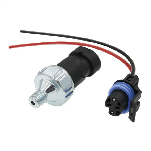
and the new oil pressure safety switch in the remaining two holes. 5. Screw in the two switches and reconnect the lead to the original equipment oil pressure switch. NOTE: The pump oil pressure switch will normally have three terminals marked: C (common), NC (normally closed), and NO (normally open). 6. Connect the fuel pump (red lead) to the.
The oil pressure switch sends a signal to the pump/relay as well as the dash if pressure gets low pump quits. But since you disconnected it it can't do that as well as give any oil pressure readings. If the low oil level light is on and you haven't checked the oil then it may be so or it's a bad sensor/shorted wire. See pic.
20. Jun 25, 2007. #3. Re: Oil Pressure switch Diagram. see the thing is the guy had it wired to a toggle so you could hold the toggle, prime the pump and fire it up if it sat for a while. well i dont even think the starter solenoid terminal has a wire to the switch on it, and when it died in the water all of a sudden, the two wires i took off.
then the oil pressure switch takes over and keeps the pump on. theres 3 wires on the oil pressure switch the center wire works the light the left one is fuel pump fuse power and the right one is the fuel pump. the oil switch can go bad and the connection can go bad the wire can fall off or get broken. the wire to the fuel pump may not get all.
The NC side has a wire from the starter solenoid " start " terminal, The NO side wire is + 12volts when the key is on. The 3rd wire goes to the electric pump. The NC circuit supplies 12 volts to the pump when starting, the NO circuit supplies 12 volts to the pump when the ignition is on and there is oil pressure, I believe 12-15 # or more.
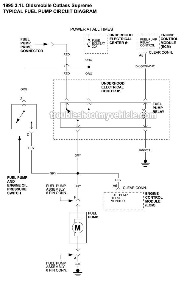
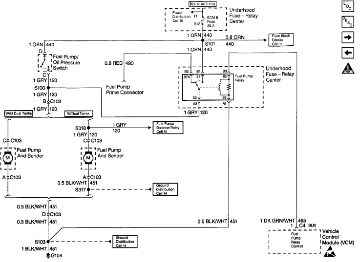
according to my 1994/5 s10 diagram the orange is the feed 12volts from the ecm fuse. this goes to the switch of this oil sender/pressure switch. the other side of the switch is the grey wire. that wire goes to the ecm input and the fuel pump motor. so I would jump the orange to the grey wires.
The high-pressure switch is designed to shut down the compressor if the line pressure gets dangerously high. This will usually happen when a condenser fan fails. The low-pressure switch is designed to shut the compressor down if the pressure becomes to low or the evaporator freezes. The oil for the compressor is suspended in the Freon, and if a.
I don't have a diagram, but I can describe it. Find a switched power source. Fused 10 ga wire goes into post 30 on the relay with a jumper to post 86. Out from post 87 goes a 10 ga (or sufficient) wire to the fuel pump. Post 85 will go to a normally-open oil pressure switch. That is to say, an oil pressure switch that grounds when it has pressure.
Oct 21, 2021 · C4 Tech/Performance - Fuel pressure Issue - Hello all. I just put on a new headlight motor and all works well now! But I have been working on the car for a few days now and noticed fuel in my oil. So i pulled all of the oil out, smells like gas. Saw gas in the FPR vacuum hose so I got a new FPR and PCV valve just in...
Jul 15, 2003. Location: Redmond, Wa, USA. Hi All, I'm getting the wiring ready for my in tank electric fuel pump. The below wiring diagram is how I am wiring it up, I added some of my own wire colors in the pic. I'm using a PS140 pressure sensor which should be the same as the below NC, C, NO. I've hit a snag where I believe I just have the NC.
Oil pressure switch never turns the fuel pump off, only on. Turning the ignition key off is the only way to shut off the fuel pump (or the relay has to fail and the oil pressure needs to drop below 4 PSI). Switch and relay are wired in parallel. I think this would make much more sense if you looked a wiring diagram.
4. Screw a 1/8” pipe tee onto the nipple and position it in a manner to facilitate the installation of the original oil pressure switch and the new fuel pump pressure switch in the remaining two holes. 5. Screw in the two switches and reconnect the lead to the original equipment oil pressure switch.
Fuel Pump Wiring Diagram. Fuel Pump Troubleshooting Notes: Oil pressure switch: If the fuel pump relay fails, what usually happens is that the oil pressure switch feeds power to the fuel pump and gets the engine started and keeps it running. When this happens, the engine will crank till the oil pressure gets up and the oil pressure switch closes.
Auto Parts Accessories Marine Oil Pressure Switch Fuel Pump Safety For Rotary Electric Motors. Electric fuel pump wiring diagram safety switch for holley 12 801 1 technical install how to wire an conversion g503 in boating my circuits with a the cj2a page three g oil pressure and would not energize on rewire relay mod premium hd 30 amp kit yacht ready consultants rotary update fg1052 fg1053.
Re: Oil pressure Switch Wiring For Fuel Pump. You have the NO and NC on your drawing reversed, along with the 85 and 86 terminals on the fuel pump relay. For the power for the switch that you now have coming from the starter, it should be coming from the purple wire, that way the power to the oil pressure switch gets shutoff when the switch is.
SOURCE: 1988 chevy 2500 5.7 no por to fuel pump fuse. Fuel pump fuse is cut out by a relay and I believe the oil pressure switch. The goal is to have the fuel pump shut down automatically if there is an accident and the engine stops. Posted on Jan 03, 2010
The Holley P/N 12-810 fuel pump pressure safety switch is a good peace of mind to help save your engine in the unlikely event of oil pressure loss. The safety switch is installed in conjunction with the oil pressure switch and if a loss of oil pressure should occur, the switch will remove power from the electric fuel pump stalling the engine due to a loss of fuel. This safety switch can help.
Joined Sep 2, 2006. ·. 8,871 Posts. #2 · Jul 26, 2015. 1967 chevelle said: I'm installing an electric fuel pump and want to include in my circuit a Relay, Circuit breaker & Oil Pressure Safety Switch. I did some research online and found a wiring schematic. I have a few questions, on the Oil pressure safety Switch "I" terminal where is the.
Oil Pressure Gauge Installation. Oil pressure switch wiring diagram digifizmini air ride vega sending unit question sensor help electric fuel pump and 3 wire 2 understanding mins marine sel circuit with danfoss mp 54 installation manual pdf safety vdo gauge what is an on a 2005 tahoe instructions typical layout australian land rover owners engine operating technical information sfi system w o.
A fuel pump is a component in motor vehicles that transfers liquid from the fuel tank to the carburetor or fuel injector of the internal combustion engine.. Carbureted engines often use low pressure mechanical pumps that are mounted outside the fuel tank, whereas fuel injected engines often use electric fuel pumps that are mounted inside the fuel tank (and some fuel injected engines have two.








0 Response to "39 Fuel Pump Oil Pressure Switch Diagram"
Post a Comment