39 Fe Al Phase Diagram
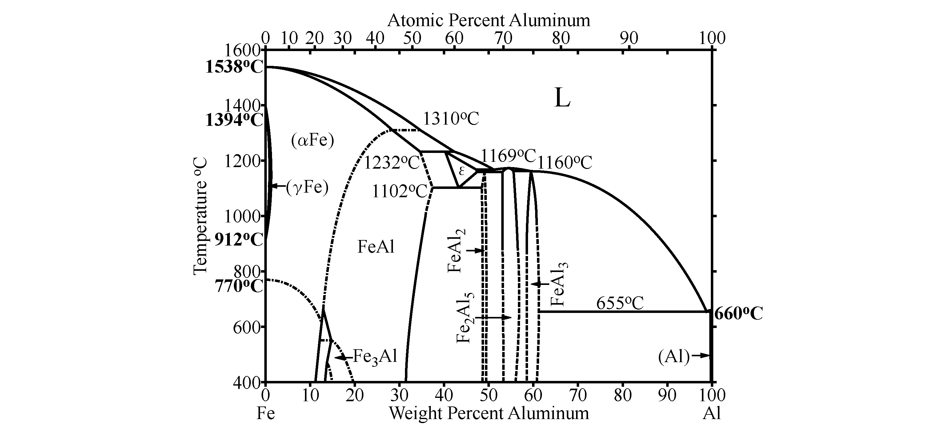
The Al-rich part of the Fe-Al phase diagram between 50 and 80 at.% Al including the complex intermetallic phases Fe5Al8 (ε), FeAl2, Fe2Al5, and Fe4Al13 was re-investigated in detail. A series of. On the Phase Diagrams of the Al-Fe and Al-Fe-Si Systems p.331. Recrystallization in Supersaturated Al-Fe, Al-Si and Al-Fe-Si Alloys: A Differential Scanning Calorimetry Study p.337. Effect of Heat Treatment on the Microstructure of Cast Al-Fe-Si Alloys p.343. The Microstructure of Al-Fe-Si, Al-Fe-Mn-Si and Al-Fe-Mn-Mg-Si Rolling Ingots in.
Equilibrium diagram for the system NiO-Al z 0 (31) , 3 Equi'librium diagram for the system NiO-Alz0 3 (32).. The Fe-O phase diagram (35,36).., Variation of wustite composition with 0z pressure and temperature. Fe-Al Sy~(8),. Fe-Al-Oisotherms proposed in reference (49) at 1000°C (a), l250°C (b), and 13500 C (c), NaA10Z-A1203 system as.

Fe al phase diagram
the Fe-Al-Zr phase diagram,[34] values of 1.8, 2.2, 0.7 at.% were given for the widths of the homogeneity ranges of these intermetallic compounds at 1000 C. Summarizing the above and having in mind that several lines in the Al-rich part of the Fe-Al phase diagram are still 1. Introduction. The Al 2 O 3 -Fe 2 O 3 -FeO system is of special industrial importance. The phase diagram of this system is widely applied to important metallurgical processes, such as deoxidation and ladle refining of molten steels ,.The information on the phase relations is also important for understanding and analysis of thermite reactions between Al 2 O 3 and iron , reactions of. % Al and Fe. In addition to equilibria with the O 1 and η phases, this phase also participates in equilibria with the < Al 13 Fe 4 >, θ phase (based on Al13Cr2), and aluminum-based solid solution. The three-phase O 1 + H + + < Al 13 Fe 4 > and H + η + θ fields exist at 998 and 750°C. The positions of the respective tie-line triangles are.
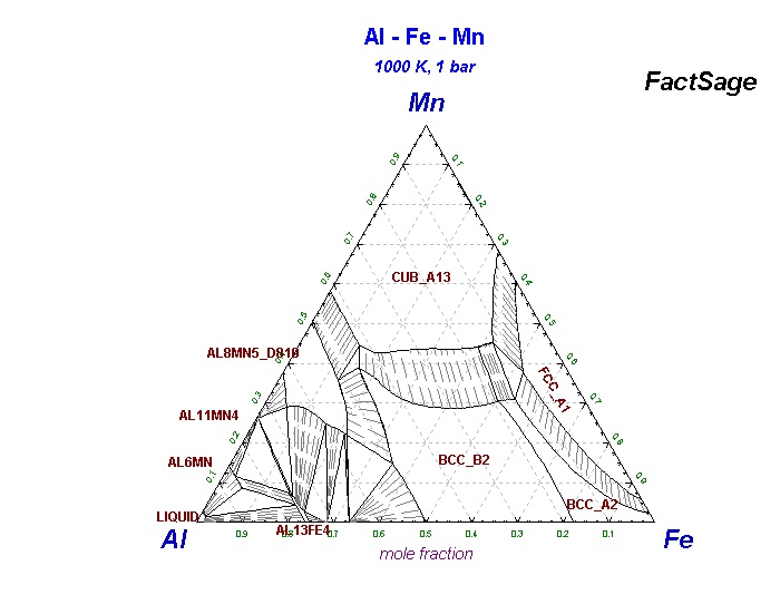
Fe al phase diagram. the Fe-Al-Zr phase diagram,[34] values of 1.8, 2.2, 0.7 at.% were given for the widths of the homogeneity ranges of these intermetallic compounds at 1000 C. Summarizing the above and having in mind that several lines in the Al-rich part of the Fe-Al phase diagram are still drawn as dotted lines today, it can be stated that this part of The Al-rich part of the Fe-Al phase diagram between 50 and 80 at.% Al including the complex intermetallic phases Fe 5 Al 8 (ε), FeAl 2, Fe 2 Al 5, and Fe 4 Al 13 was re-investigated in detail. A series of 19 alloys was produced and heat-treated at temperatures in the range from 600 to 1100 °C for up to 5000 h. Sep 05, 2020 · Correct interpretation of Fe-Al phase diagram is of critical importance for applying Fe-Al alloys in most applications. Fe-rich part of binary Fe-Al phase diagram consists of three main phases: the disordered A2-phase (α-Fe, space group Im3m), the ordered B2-phase (FeAl, space group Pm3 m) and the ordered DO 3-phase (Fe 3. 2.2. Al-Fe-^Mg PHASE DIAGRAM This phase diagram can be used to analyze the effect of iron on the phase compo sition of Al-Mg alloys with low concentrations of silicon and manganese. Examples of such alloys are given in Table 2.5. No ternary compounds have been found in the ternary Al-Fe-Mg system
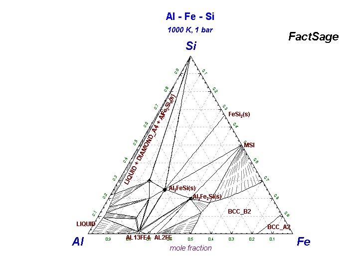
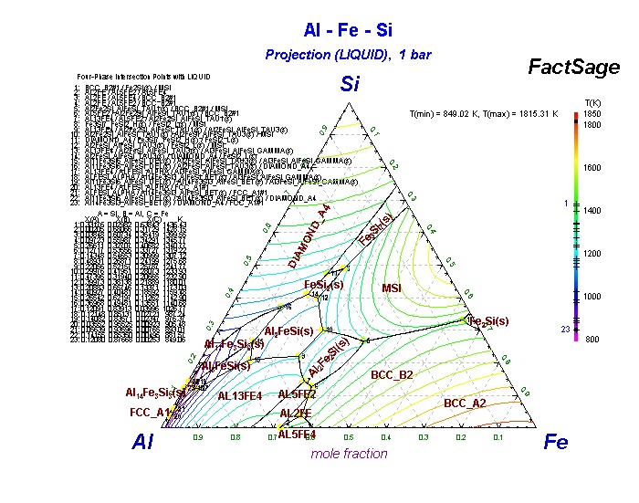
Si/Al Phase Diagram Most Si/Al alloys are cast near this eutectic point, they are cheap to manufacture; but cuboid Si flakes cause brittleness. Doping with 0.01% Na alters the compositional and temperature of the eutectic point (red lines): Alloy 2, which has the same relative amounts of Si and Al, now preciptates in a hypoeutectic fashion. % Al and Fe. In addition to equilibria with the O 1 and η phases, this phase also participates in equilibria with the < Al 13 Fe 4 >, θ phase (based on Al13Cr2), and aluminum-based solid solution. The three-phase O 1 + H + + < Al 13 Fe 4 > and H + η + θ fields exist at 998 and 750°C. The positions of the respective tie-line triangles are. The diffractogram of sample #12 (Al 48 Fe 37 Si 15) annealed at 900 °C showing the three-phase field of [AlFe + Al 5 Fe 2 + τ 12] and with τ 12 as the main phase is given in Fig. 8. The percentage of phases given in Fig. 8 , correspond to the refined area of the powder pattern and are in good agreement with expectations from the lever rule. 1 The specific phase Al 5 Fe 2 is important as it forms at the junction layers of Fe with Zn during galvanizing treatments. Our own interest in the Al-Fe phase diagram derives from its complex and.
the Fe-Al-Zr phase diagram,[34] values of 1.8, 2.2, 0.7 at.% were given for the widths of the homogeneity ranges of these intermetallic compounds at 1000 C. Summarizing the above and having in mind that several lines in the Al-rich part of the Fe-Al phase diagram are still The thermodynamic models used to describe the Fe-Al phase diagram are studied in detail. We calculate the phase diagram of Fe-Al within the Bragg-Williams approximation and the tetrahedron approximation of the cluster-variation method, including nearest- and next-nearest-neighbor chemical and magnetic interactions. In contrast to previous calculations performed within the Bragg-Williams. 1.1. Al-Fe-Si PHASE DIAGRAM The Al-Fe-Si system is the basic system for the structure analysis of commercial aluminum alloys of the 8111 type, and binary Al-Si alloys which, as a rule, contain an iron impurity (Table 1.1). The aluminum corner of the Al-Fe-Si phase diagram is considered in detail by Phillips (1959), who gives the isotherms of. For the phase diagram calculations of Fe-Cr-Al alloy, we only consider bcc and bcc superstructures. The energy convex hulls of Fe-Cr, Fe-Al, and Cr-Al are shown in Fig. 2, and the formation energies for non-bcc stable structures FeAl 6-Cmcm, Cr 2 Al-I4/mmm, CrAl 3-I4/mmm and Cr 7 Al 45-C2/m from USPEX , calculations are also included. These non-bcc stable phases are consistent with the phases.
Dissimilar Metal Joining Of Zinc Coated Steel And Aluminum
Though, it is noted that according to the phase diagram shown in Fig. 1 a two-phase field α-(Fe,Al)+Fe 3 Al exists which apparently extends to even lower Al contents than shown in Fig. 1. At 300 °C Ikeda et al. [24] found the A2/A2+D0 3 phase boundary at about 17 at.% and according to the slope of their data this phase boundary could extend.

Al Cr Fe Phase Diagram Isothermal Sections In The Region
Iron-rich Fe-Al binary phase diagram in the composition range of 23-26 at% Al shows a complex structure partly due to magnetic properties of the disordered A2-phase, the ordered B2-phase and the ordered DO 3-phase.In this study, the disorder-order transformations between the constituent phases have been investigated through magnetization measurements of Fe-xAl alloys (x = 22.0, 24.0, 24.3.
Phase Diagrams Shuanglin Chen
The maximum solubility of zinc was found to be 5·3 wt-% in FeAl 3, 20·9 wt-% in Fe 2 Al 5, and 2·0 wt-% in FeAl at 450°C. Based on these results, an isothermal section for the aluminium rich corner of the Fe-Al-Zn ternary phase diagram is proposed.

Figure 1 Aluminising Of Mild Steel Plates
L. Zhang and R. Luck, Phase Diagram of the Al-Cu-Fe Quasicrystal Forming Alloy System: IV. Formation and Stability of the φ-Al 10 Cu 10 Fe 1 Phase, Z. Metallkde., Vol 94 (No. 3), 2003, p 341-344. Google Scholar 2003Zha5: L. Zhang and R. Luck, Phase Diagram of the Al-Cu-Fe Quasicrystal Forming Alloy System. V.
Interpretation Of Fe Rich Part Of Fe Al Phase Diagram From
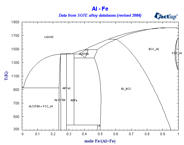
Al-Fe Phase Diagram. Thermodynamic Assessment [1989Sei] M.Seiersten, unpublished work (1989). Available in SSOL2 and BIN database. [1993Kat] U.R.Kattner and B.P.Burton, Phase Diagrams of Binary Iron Alloys, (Ed.)H.Okamoto, ASM International, Materials Park, OH, 12-28 (1993). TDB File.

The Fe Al Binary Phase Diagram Download Scientific Diagram
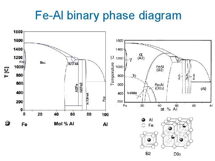
The Fe-Al equilibrium phase diagram is shown in Figure 1, the IMP with allowable mechanical properties in case of weldings is marked. The system is characterized with an iron-based solid solution and six non-stoichiometric intermetallic compounds of Fe 3Al, FeAl (D 2), FeAl 2, Fe 2Al 3 (H), Fe 2Al 5 and FeAl 3. Table 1 indicates crystal.

Experimental Determination Of Order Parameters Condensed
The decagonal quasi-crystalline phase q (Fe 4.9 Ni 23.4 Al 71.7) was found to be stable between 850 °C and 930 °C. All experimental data were combined to yield a ternary reaction scheme (Scheil diagram) involving 10 ternary invariant reactions in the investigated composition range, and a liquidus surface projection was constructed based on.
Phase Diagrams As Tools For Advanced Materials Design
The Al-rich part of the Fe-Al phase diagram between 50 and 80 at.% Al including the complex intermetallic phases Fe$_{5}$Al$_{8}$ (ε), FeAl$_{2}$, Fe$_{2}$Al$_{5.

Thermodynamic Evaluation Of Sr Containing Si Metals And
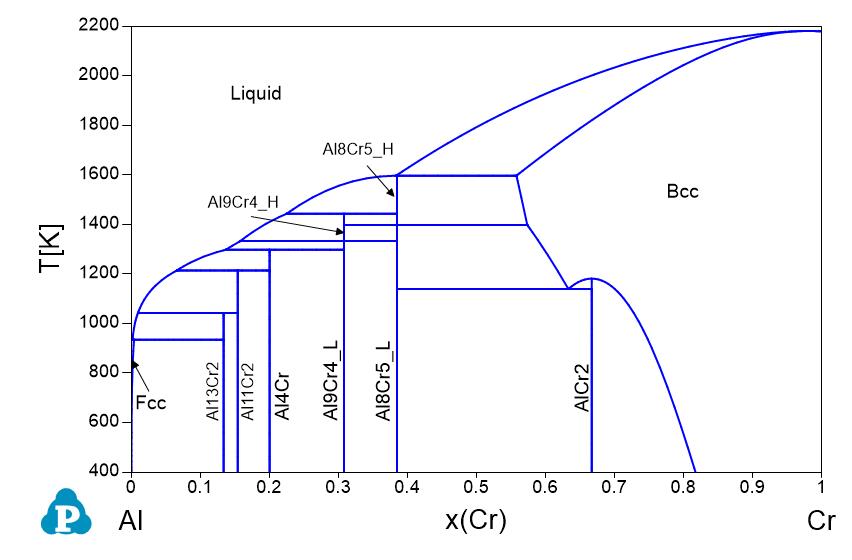
Phase diagrams of the Al–Fe (a) and Al–Cr (b) boundary binary systems over the range. between 58 and 100 at.% Al. Al 75 Cr 16 Fe 9 alloys annealed at 1000°C contain one phase.
Thermodynamic Assessment Of The Aluminum Corner Of The Al Fe
Al-Fe-P_1173K FSstel: Al-Fe-S_FeS-Al2S3 FTOxCN: Al-Fe-S2_900C FTOxCN: Al-Fe-Si_550C FSstel: Al-Fe-Si_1000K SGTE 2014: Al-Fe-Si_500K SGTE 2014. Al-Fe-Si_liquidprojection SGTE 2014: Al-Fe-Si_1000K SGTE 2017: Al-Fe-Si_1500K SGTE 2017: Al-Fe-Si_500K SGTE 2017: Al-Fe-Si_liq SGTE 2017: Al-Fe-Si_1000 SGTE 2020: Al-Fe-Si_1500 SGTE 2020: Al-Fe-Si_500.
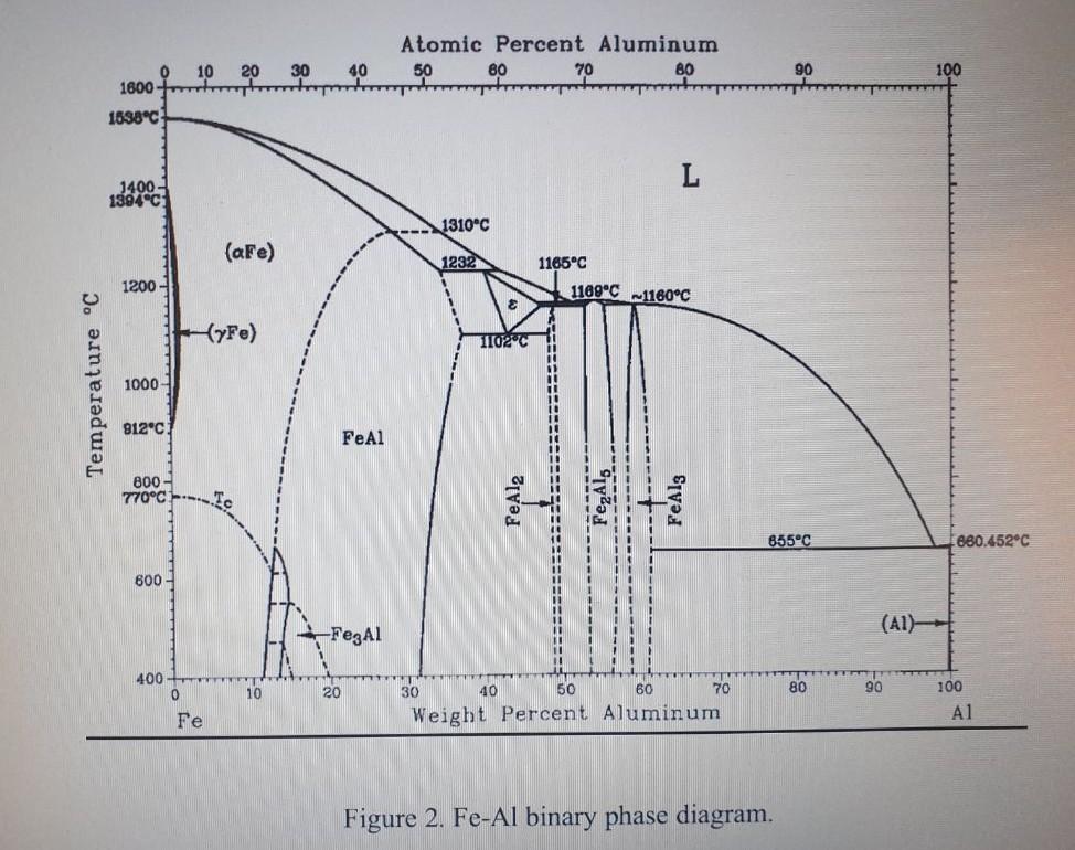
Solved Question 2 10 Marksi Figure 2 Shows The Fe Al Binary
the Fe-Al-Zr phase diagram,[34] values of 1.8, 2.2, 0.7 at.% were given for the widths of the homogeneity ranges of these intermetallic compounds at 1000 C. Summarizing the above and having in mind that several lines in the Al-rich part of the Fe-Al phase diagram are still drawn as dotted lines today, it can be stated that this part of the Fe

Fe Al Binary Phase Diagram 12 Download Scientific Diagram
Review Fe-C phase diagram • 2 important points-Eutectoid (B): γ⇒α+Fe 3C-Eutectic (A): L ⇒γ+Fe 3C Fe 3 C (cementite) 1600 1400 1200 1000 800 600 400 0 12 3 4 5 66.7 L γ (austenite) γ+L γ+Fe 3C α+Fe 3C α + γ L+Fe 3C δ (Fe) C o, wt% C 1148°C T(°C) α 727°C = Teutectoid A R S 4.30 Result: Pearlite = alternating layers of αand Fe.

Al Fe Thermodynamic Assessment
Phase Diagrams of Fe-Si Alloys under High Pressures J. F. Lin,1 D.L. Heinz,1,2 A. J. Campbell,1 J. M. Devine1 1Department of the Geophysical Sciences and 2James Franck Institute, The University of Chicago, Chicago, IL, U.S.A. Introduction Iron is the most abundant element in the Earth's core.
Al Rich Fe Al Based Alloys Phase Equilibria
1. Introduction. The Al 2 O 3 -Fe 2 O 3 -FeO system is of special industrial importance. The phase diagram of this system is widely applied to important metallurgical processes, such as deoxidation and ladle refining of molten steels ,.The information on the phase relations is also important for understanding and analysis of thermite reactions between Al 2 O 3 and iron , reactions of.
Collection Of Phase Diagrams

Scielo Brasil Experimental And Computer Thermodynamics
Collection Of Phase Diagrams

Interpretation Of Fe Rich Part Of Fe Al Phase Diagram From
Al Rich Fe Al Based Alloys Phase Equilibria
Collection Of Phase Diagrams

Fe Al Binary Phase Diagram 12 Download Scientific Diagram

Phase Diagrams And Elastic Properties Of The Fe Cr Al Alloys

Characterization Of The Fe Rich Corner Of Al Fe Si Ti

Thermodynamic Assessment Of The Fe Al Zr Phase Diagram

Interpretation Of Fe Rich Part Of Fe Al Phase Diagram From
The Fe Al Binary Phase Diagram Download Scientific Diagram

Al Fe Phase Diagram And Database Gedb For Factsage

Figure 1 From Plastic Deformation Of Fe Al Polycrystals

The Al Si Phase Diagram The Fe Is Present As Al 3 Fe

12 Binary Fe Al Phase Diagram 23 Download Scientific Diagram
Binary Phase Diagram Of Fe Al A Fe Al Si B Feal2

Development Of Thermodynamic Database For High Mn High Al
Collection Of Phase Diagrams

Scielo Brasil Nb Al Binary System Reevaluation Of The
Recent Development Of Lightweighting Steels Graduate Institute Of
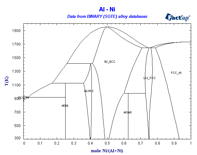
Binary Sgte Alloy Phase Diagrams
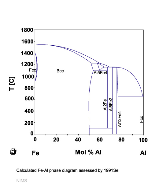
Al Fe Nims

Pauling File

Fe Al Materials For Structural Applications At High
0 Response to "39 Fe Al Phase Diagram"
Post a Comment