39 Eeg Lead Placement Diagram
3 lead ECG cable Placement (there are two ways) Way 1. Monitors one of the three leads: RA: placed the red electrode within the frame of rib cage,right under the clavicle near shoulder( see chart in follow picture) LA: the yellow electrode is placed below left clavicle, which is in the same level of the Red electrode ECG limb lead placement diagram. Watch a video on ECG lead/electrode placement . Chest (Precordial) Lead Placement . V1: 4th intercostal space, right sternal border. V2: 4th intercostal space, left sternal border. V3: Midway between leads V2 and V4. V4: 5th intercostal space, midclavicular line. V5: 5th intercostal space, anterior axillary line
EEG measures electrical activity of the brain. The brain consists of billions of cells, half of which are neurons, half of which help and facilitate the activity of neurons. These neurons are densely interconnected via synapses, which act as gateways of inhibitory or excitatory activity. Any synaptic activity generates a subtle electrical.

Eeg lead placement diagram
Mar 30, 2016 · EEG Wednesday, March 30, 2016 77 Electrical Activity of the brain EEG electrodes are smaller than ECG It is an Effective method for diagnosing many neurological, disorder such as epilepsy, tumour etc. 77. EEG Electrode Placement Wednesday, March 30, 2016 78 78. Place limb leads on soft tissue surfaces & not the bone according to the diagram on above. Black LA = Upper Left Arm Red LL – Lower Left Leg 12 Lead ECG Placement. 4th intercostal space to the right of the sternum 4th intercostal space to the leftofthe sternum directty between the & V, 5th intercostal space at rrÝdclavicular Ene EEG disk electrodes, however, require the use of a conductive cream. Within a few days of application, the cream will dry or be absorbed, causing higher im-pedances. This process requires re-prepping and/or re-application of electrodes.
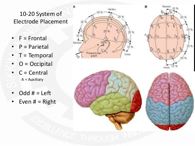
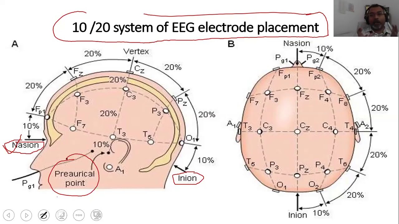
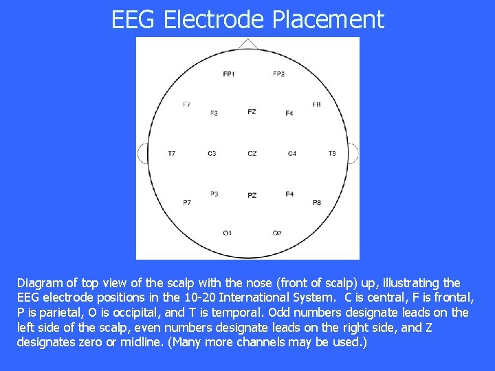
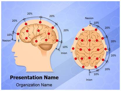
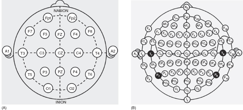
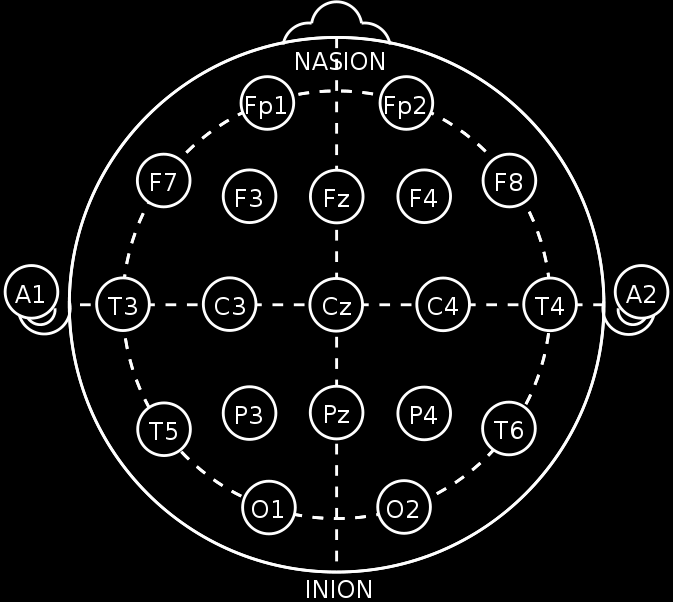
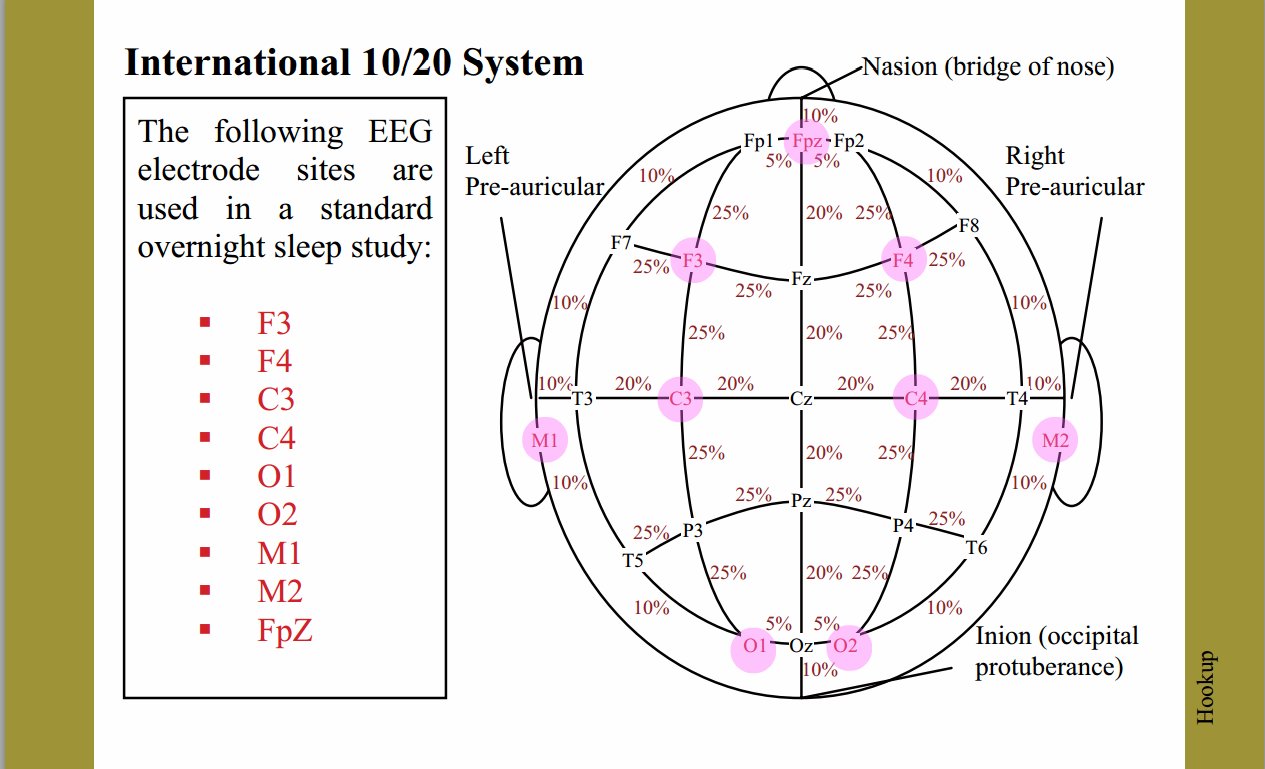
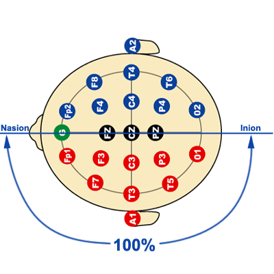
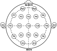
Eeg lead placement diagram. EEG Lead System. International Federation of EEG society has suggested 10 – 20 electrode placement system for EEG recording.Silver / silver chloride electrodes are used as surface electrodes in this setup. On the scalp, distances between two electrodes are given as 10% and 20% of the distance between specified points. Measuring for Full EEG ‐Step 2 • Measure the distance between the left and right preauricular points. (e.g.: 35 cm) • Mark 50% of this distance (17.5 cm)along the midline. This is the second mark for CZ. • Measure up 10% (3.5 cm)from the right preauricular point and mark for T4. EEG disk electrodes, however, require the use of a conductive cream. Within a few days of application, the cream will dry or be absorbed, causing higher im-pedances. This process requires re-prepping and/or re-application of electrodes. Fully integrated, single-lead ECG front end A4 Low quiescent supply current: 50 µA (typical) Leads on/off detection while in shutdown (<1 µA) FR. Common-mode rejection ratio: 80 dB (dc to 60 Hz) 2-electrode and 3-electrode configurations. High signal gain (G = 100) with dc blocking capabilities . 2-pole adjustable high-pass filter
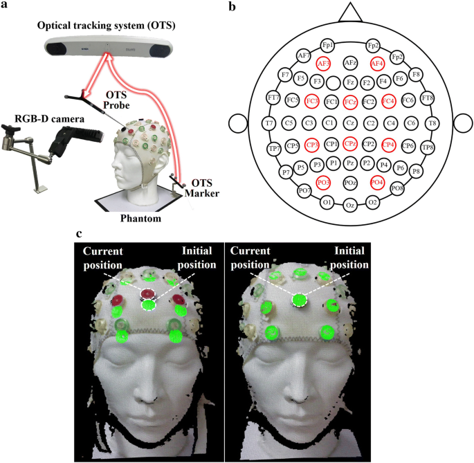
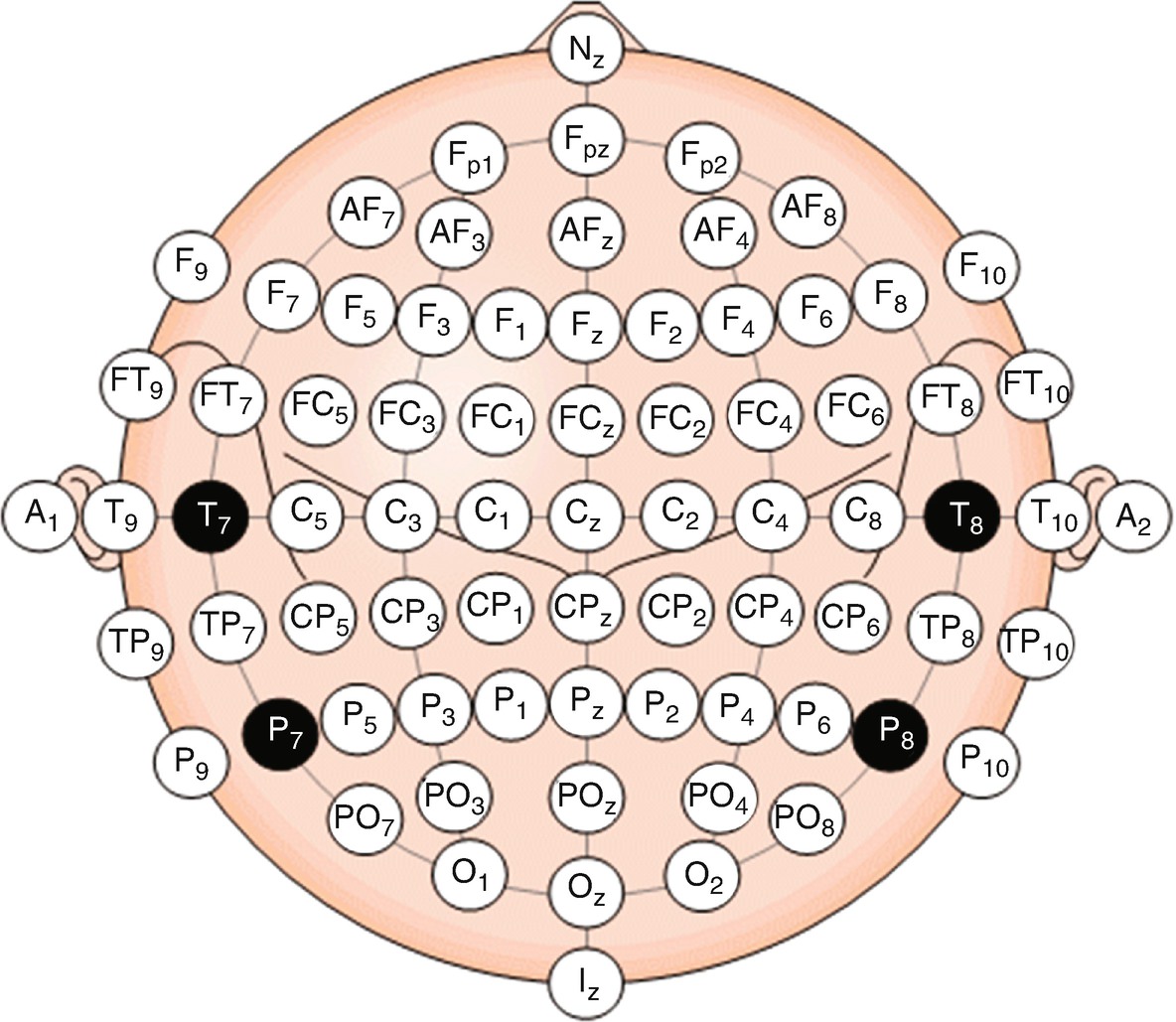
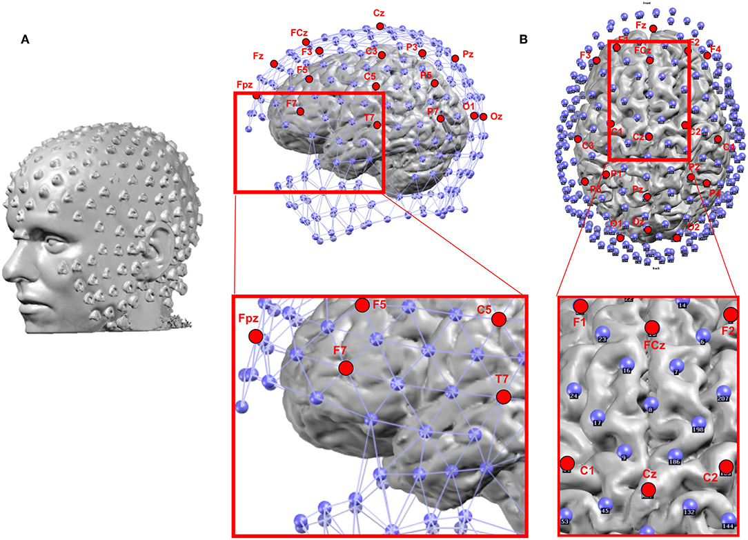
12-Lead ECG Electrode Placement Explained. One of the most common questions related to 12-lead ECG electrode placement is why there are only 10 electrodes. It's very important to understand what the term "lead" really means. A lead is a view of electrical activity of the heart from a specific angle across the body. With the availability of EEG systems capable of recording with a greater number of channels (e.g. 128, 256), there is a need to standardize placement of additional electrodes. A further extension of the 10-10 system, called the 10-5 system, has been proposed, 4 but Nov 09, 2021 · Lead seizures were defined as seizures separated from preceding seizures by at least 4 h, and clustered (i.e., non-lead) seizures were excluded from analysis to avoid artificially inflating results. DIY EEG (and ECG) Circuit: EEGs are a noninvasive way to look into your brain. While the brain is extremely complex, areas of it can lock into circular firing patterns, resulting in telltale brain waves that one can observe with the right equipment. Intensity of these waves c…
recording of sleep requires measurement of brain activity (EEG), eye mov ement (EOG) and muscle activity (EMG). On the following page are examples of how the following stages appear on a polygraph record of EEG: Wakefulness - (Awake and Drowsy patterns) Note how irregular the pattern looks. 5-lead monitoring is the same as 3-lead monitoring, but with two additional electrodes that enable the monitoring of extra leads and help improve ST elevation readings (Cables and Sensors 2016). It is able to monitor the leads I, II, III, aVR, aVL, aVF and V (Phillips 2008). The normal sinus rhythmm, as seen in 12-lead monitoring. to display up to 256 channels in modern digital EEG machines, provides the ability to create an even greater number of montages. However, from a clinical and practical standpoint, only a limited number of montages need to be used during a recording session. A great diversity of montages exists among different EEG laboratories, but many of Additional Lead placements Right sided ECG electrode placement. There are several approaches to recording a right-sided ECG: A complete set of right-sided leads is obtained by placing leads V1-6 in a mirror-image position on the right side of the chest (see diagram, below).

10 20 System Eeg Wikipedia
20-lead, 4 mm × 4 mm LFCSP and LFCSP_SS package. Qualified for automotive applications . APPLICATIONS Fitness and activity heart rate monitors . Portable ECG . Remote health monitors . Gaming peripherals . Biopotential signal acquisition . FUNCTIONAL BLOCK DIAGRAM LOD– LOD+ AD8232 +V S GND SW OPAMP+ REFOUT OPAMP– OUT HPSENSE IAOUT REFIN.
Eeg
Biofeedback is the process of gaining greater awareness of many physiological functions of one's own body, commercially by using electronic or other instruments, and with a goal of being able to manipulate the body's systems at will. Humans conduct biofeedback naturally all the time, at varied levels of consciousness and intentionality. Biofeedback and the biofeedback loop can also be thought.
How To Place Electrodes For Eeg 10 20 System Of Electrode Placement Eeg Electrode Placement Map
Download scientific diagram | The International 10-20 system of electroencephalogram (EEG) lead placement. In neonates, only the shaded electrodes are placed on the smaller neonatal scalp for.
Eeg Wiki Google Search
1 - 6 A third electrode placement, termed bifrontal, in which the electrodes are placed on either side of the forehead above the eyes, has come into use but there are no data about any possible neurophysiological differences as reflected in the ictal EEG with this placement vis a vis the other two placements.

Eeg Electrode Placement Eps10 10 20 System Electrodes
12-Lead ECG Placement Guide with Illustrations. As a non-invasive yet most valuable diagnostic tool, the 12-lead ECG records the heart's electrical activity as waveforms. When interpreted accurately, an ECG can detect and monitor a host of heart conditions — from arrhythmias to coronary heart disease to electrolyte imbalance.
Chapter 12 Case Studies Case Study Eeg Spike
EEG electrode placement is a critical part of successful qEEG. Traditional EEG lead placements follow the 10-20 system, an internationally recognized standard for applying the electrodes attached to your scalp. "10-20" refers to the distance between EEG leads being 10% or 20% of the total distance of the skull.

Electrode Positions Details Hackaday Io
• Pre-cordial lead placement - Angle of Louis -V1 - What about breast tissue? How to read an EKG • The Paper • The Waveform •The Panl. How to read an EKG • The paper - Up and down 1 box = 0.1 mV -Across 1 box = 4 ms • The rate - 10 seconds per page. How to read an EKG • The Waveform.

Figure 5 Ipsilateral Ear Referential Montage Eeg
•Primer of EEG with a Mini-Atlas. AJ Rowan and E Tolusky. Butterworth Heinemann 2003 •Atlas of EEG in Critical Care. LJ Hirsch and RP Brenner. Wiley Blackwell 2010 •Prognostic value of continuous EEG monitoring during therapeutic hypothermia after cardiac arrest. AO Rossetti et al. Critical Care 2010 (14): R173
The 10 20 International System Of Electrode Placement
Electrocardiography is the process of producing an electrocardiogram (ECG or EKG).It is an electrogram of the heart which is a graph of voltage versus time of the electrical activity of the heart using electrodes placed on the skin. These electrodes detect the small electrical changes that are a consequence of cardiac muscle depolarization followed by repolarization during each cardiac cycle.
Augmented Reality Based Electrode Guidance System For
The first step to any EEG study is the placement of the electrodes, and this is most commonly done via the international, standardized 10-20 System. This system is so named because it splits the skull into increments of 10% or 20% to place the electrodes, ensuring that each electrode is relatively positioned to all the others and making it.
10 20 Eeg Placement
Additional notes on 12-lead ECG Placement: The limb leads can also be placed on the upper arms and thighs. However, there should be uniformity in your placement. For instance, do not attach an electrode on the right wrist and one on the left upper arm. For female patients, place leads V3-V6 under the left breast.

Eeg Electrode Placement
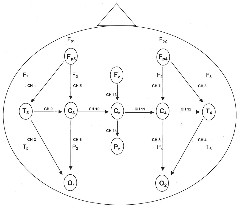
electrode. Ensure that the lead is secure within the cable. If this does not correct the problem, change the "partner electrode". This is identified by the colored line in the diagram (purple for this example). It can also be identified in the Impedance Limit (the two leads required for EEG channel 4 in this example is F8 and T6. 6

Eeg Recording
Jan 01, 2021 · EEG electrodes placement according to the 10-20 system. The related motor imagery electrodes are identified in blue color. Despite the inherent drawbacks in raw EEG, it has some advantages over other neurological imaging techniques.
Normal Pediatric Eeg Neonates And Children Thoracic Key
Press 1 lead onto the left shoulder below the clavicle. As on the right arm, this lead should fall about 2 inches (5.1 cm) below the clavicle. Place the lead at roughly the same location as you placed the lead on their right side to ensure that both arm leads give accurate readings. Press down firmly on the lead to fix it in place.

Neurofeedback A Comprehensive Review On System Design
Electrode Placement. Accurate placement of many electrodes on the scalp is time consuming and requires practice. EEG caps greatly facilitate this process. These caps are made of elastic fabric (often available in different sizes), and electrodes are already fixed in the proper configuration.
Free Eeg Electrode Placement Medical Powerpoint Template For
ECG leads: from electrodes to limb leads, chest leads & 12-lead ECG. Before discussing the ECG leads and various lead systems, we need to clarify the difference between ECG leads and ECG electrodes.An electrode is a conductive pad that is attached to the skin and enables recording of electrical currents. An ECG lead is a graphical description of the electrical activity of the heart and it is.

Eeg Electrode Placement And The 4 Rois Download Scientific
The 10-20 system or International 10-20 system is an internationally recognized method to describe and apply the location of scalp electrodes in the context of an EEG exam, polysomnograph sleep study, or voluntary lab research.This method was developed to maintain standardized testing methods ensuring that a subject's study outcomes (clinical or research) could be compiled, reproduced, and.
Eeg Instrumentation Neupsy Key
• Describe specific measures to make a child more comfortable in the EEG lab, in preparation for head measurement and lead placement • Explain lead placement techniques to ensure good lead placement without injury to the child • List the pros and cons of using sedation for lead placement for the pediatric patient,
Overview Of Eeg Electrode Placement And Montages Springerlink
Place limb leads on soft tissue surfaces & not the bone according to the diagram on above. Black LA = Upper Left Arm Red LL – Lower Left Leg 12 Lead ECG Placement. 4th intercostal space to the right of the sternum 4th intercostal space to the leftofthe sternum directty between the & V, 5th intercostal space at rrÝdclavicular Ene
The Hardware Openld Electrodes Details Hackaday Io
EEG Electrode Placement. Create healthcare diagrams like this example called EEG Electrode Placement in minutes with SmartDraw. SmartDraw includes 1000s of professional healthcare and anatomy chart templates that you can modify and make your own. 8/37 EXAMPLES. EDIT THIS EXAMPLE. CLICK TO EDIT THIS EXAMPLE.

Integrating Neural Signal And Embedded System For Controlling
10-20 system EEG Placement Andrew Morley (BSc Hons, RPSGT)(BSc Hons, RPSGT) , Lizzie Hill Lizzie Hill (EST RPSGT) & Prof. Dr Athanasios G. Kaditis. Chief Respiratory (Sleep) Physiologist, Royal Hospital for Children, Glasgow. Specialist Respiratory Clinical Physiologist, Royal Hospital for Sick Children, Edinburgh
Frontiers Eeg Source Imaging A Practical Review Of The
EEG has very high time resolution and captures cognitive processes in the time frame in which cognition occurs.. Electrode arrays and placement.... they take the lead and apply automated de-noising procedures or automatically generate high-level cognitive-affective metrics which can be used in order to get to conclusions much faster.

Choosing Your Reference For An Eeg Recording And The
Mar 30, 2016 · EEG Wednesday, March 30, 2016 77 Electrical Activity of the brain EEG electrodes are smaller than ECG It is an Effective method for diagnosing many neurological, disorder such as epilepsy, tumour etc. 77. EEG Electrode Placement Wednesday, March 30, 2016 78 78.

10 20 Electrode Placement System Used In
Nov 03, 2021 · Stucynski et al. show that GABAergic neurons in the dorsomedial medulla (dmM) promote REM sleep, in part through projections to the dorsal/median raphe. During NREM sleep, these neurons fluctuate in close synchrony with an infraslow oscillation in the EEG sigma power. This infraslow rhythm influences the timing of REM sleep induction by the dmM.
A Review On Eeg Artifacts And Its Different Removal Technique

10 20 System Of Electrode Placement Download Scientific

The Correlation Between Eeg Signals As Measured In Different
The International 10 20 System Of Electrode Placement
How To Set Up Continuous Eeg Ceeg
Electroencephalography And Evoked Potentials Technical
Eeg
The Ten Twenty Electrode System International Federation Of

An Introduction To Eeg
10 20 System Positioning

Eeg Electrode Placement Eps10

10 20 International System Of Electrode Placement

Placement Of Leads For Stereotactic Electroencephalography
10 20 System Eeg Wikipedia

A Semi Schematic Diagram Depicting Dorsal And Sagittal Views
0 Response to "39 Eeg Lead Placement Diagram"
Post a Comment