39 Block Diagram Transfer Function
Example Problem on how to derive closed loop transfer function from Block Diagram Chapter 2 Transfer Functions and Block Diagrams 4 2. Transfer Functions and Block Diagrams 2.1 Introduction - Review of Laplace transform - Using Laplace transform to solve a differential equation 2.2 Review of Laplace Transforms Definition: The Laplace transform off (t) , a sectionally continuous function of time, denoted by L[ f (t)], is.
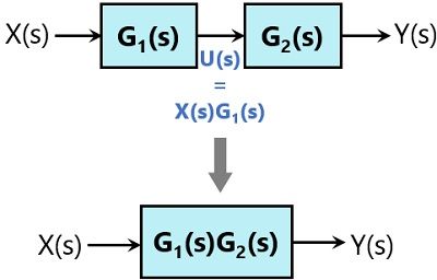
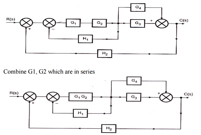
The transfer function of this single block is the product of the transfer functions of those two blocks. The equivalent block diagram is shown below. Similarly, you can represent series connection of 'n' blocks with a single block. The transfer function of this single block is the product of the transfer functions of all those 'n' blocks.
Block diagram transfer function
Transcribed image text: 3(a) Figure 5 shows the block diagram model of a dynamic system. Determine the equivalent transfer function of the system that correlates the output, C, to the input R. (5 marks) R(S) C(s) G G2 H H2 Figure 5: A block diagram. BLOCK DIAGRAM ALGEBRA AND TRANSFER FUNCTIONS OF SYSTEMS [CHAP. 7 We do not apply Step 3 at this time, but go directly to Step 4, moving takeoffpoint I b'eyond block G2 + G3: i [.1 .2 C G2 + G3 We may now rearrange summing points 1 and 2 and combine the cascade blocks in the forward loop using. Block Diagrams and Transfer Functions Just as with CT systems, DT systems are conveniently described by block diagrams and transfer functions can be determined from them. For example, from this DT system block diagram the difference equation can be determined. y[]n =2x[]n −x[ ]n−1− 1 2 y[n−1]
Block diagram transfer function. K. Webb MAE 4421 3 Block Diagrams In the introductory section we saw examples of block diagrams to represent systems, e.g.: Block diagrams consist of Blocks-these represent subsystems - typically modeled by, and labeled with, a transfer function Signals- inputs and outputs of blocks -signal direction indicated by Block Diagram Analysis For the multiloop control configuration, the transfer function between a controlled and a manipulated variable depends on whether the other feedback control loops are open or closed. Example: 2 x 2 system, 1-1/2 -2 pairing From block diagram algebra we can show Note that the last expression contains GC2. 1 11 1 P Y(s) G(s. how to simulate a transfer function in an Xcos block diagram; how to simulated a transfer function using Scilab dedicated functions; A system can be defined as a mathematical relationship between the input, output and the states of a system. In control theory, a system is represented a a rectangle with an input and output. Rules for Block Diagram Reduction. So, one by one we will discuss the various rules that can be applied for simplifying a complex block diagram. For serially connected blocks. When blocks are connected in series then the overall transfer function of all the blocks is the multiplication of the transfer function of each separate block in the.
how to simulate a transfer function in an Xcos block diagram; how to simulated a transfer function using Scilab dedicated functions; A system can be defined as a mathematical relationship between the input, output and the states of a system. In control theory, a system is represented a a rectangle with an input and output.. About Press Copyright Contact us Creators Advertise Developers Terms Privacy Policy & Safety How YouTube works Test new features Press Copyright Contact us Creators. Transfer Functions. A transfer function is a mathematical formulation that relates the output variable of a device to the input variable. For linear devices, the transfer function is independent of the input quantity and solely dependent on the parameters of the device together with any operations of time, such as differentiation and integration that it may possess. BLOCK DIAGRAM ALGEBRA AND TRANSFER FUNCTIONS OF SYSTEMS [CHAP. 7 We do not apply Step 3 at this time, but go directly to Step 4, moving takeoffpoint I b'eyond block G2 + G3: i [.1 .2 C G2 + G3 We may now rearrange summing points 1 and 2 and combine the cascade blocks in the forward loop using.
A block diagram with several transfer function can be simplified using easily derivable transformations. After several transformation we'll end up with an equivalent transfer function, input and output. Transfer functions can be arranged in series or parallel. 4.4 Block Diagrams Using the Laplace transform linearity and convolution properties we can easily extend the concept of the transfer function to configurations of several connected linear systems. In that way we will find the equivalent transfer functions for cascade and parallel connections of systems, introduce the feedback (closed-loop) 2. Block diagram models The block diagram is a diagrammatic means to represent the cause-and-effect relationship of system variables. It consists of unidirectional, operational blocks that represent the transfer function of the variables of interests. Fig.4: Components of a block diagram for a linear, time-invariant system •A Block Diagram is a shorthand pictorial representation of the cause-and-effect relationship of a system.. •The control ratio is the closed loop transfer function of the system. •The denominator of closed loop transfer function determines the characteristic equation of the system. •Which is usually determined as: ( ) ( ) ( ) ( ) ( )
Transfer Functions in Block Diagrams One source of transfer functions is from Balance Equations that relate inputs and outputs. Transfer functions are compact representations of dynamic systems and the differential equations become algebraic expressions that can be manipulated or combined with other expressions.
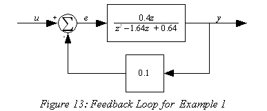
Block Diagram of Closed Loop Control System. In a closed-loop control system, a fraction of output is fed-back and added to the system's input. If H (s) is the transfer function of the feedback path, then the transfer function of the feedback signal will be B (s) = C (s)H (s). At the summing point, the input signal R (s) will be added to B (s.
Transfer Functions In this chapter we introduce the concept of a transfer function between an input and an output, and the related concept of block diagrams for feedback systems. 6.1 Frequency Domain Description of Systems The idea of studying systems in the frequency domain is to characterize a
Block Diagrams and Transfer Functions Just as with CT systems, DT systems are conveniently described by block diagrams and transfer functions can be determined from them. For example, from this DT system block diagram the difference equation can be determined. y[]n =2x[]n −x[ ]n−1− 1 2 y[n−1]
Transfer function block diagram. 1. Find the difference equation and draw the simulation diagram. 4. Find transfer function from root locus and step response diagram? 3. Poles and zeros of a transfer function. 0. Block diagram for a complex impulse response. 0. Inverse Fourier of Two-Pole Transfer Function.
This block diagram can certainly be recreated in Simulink. I suggest you start with 'Transfer Function' blocks and 'Sum' blocks, to match the transfer functions and sums in the diagram. I am not sure what the 'F' blocks in your diagram refer to, but if they are simply gains, then you can use a 'Gain' block to represent each one.
A transfer function represents the relationship between the output signal of a control system and the input signal, for all possible input values. A block diagram is a visualization of the control system which uses blocks to represent the transfer function, and arrows which represent the various input and output signals.
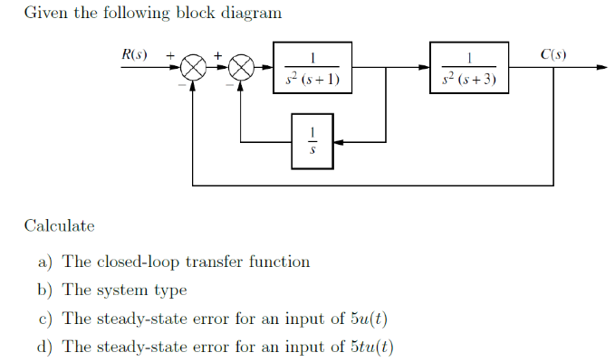
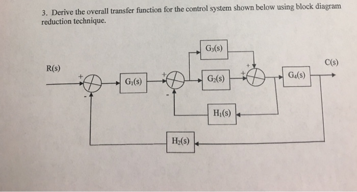
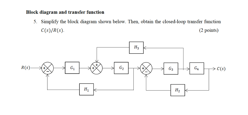
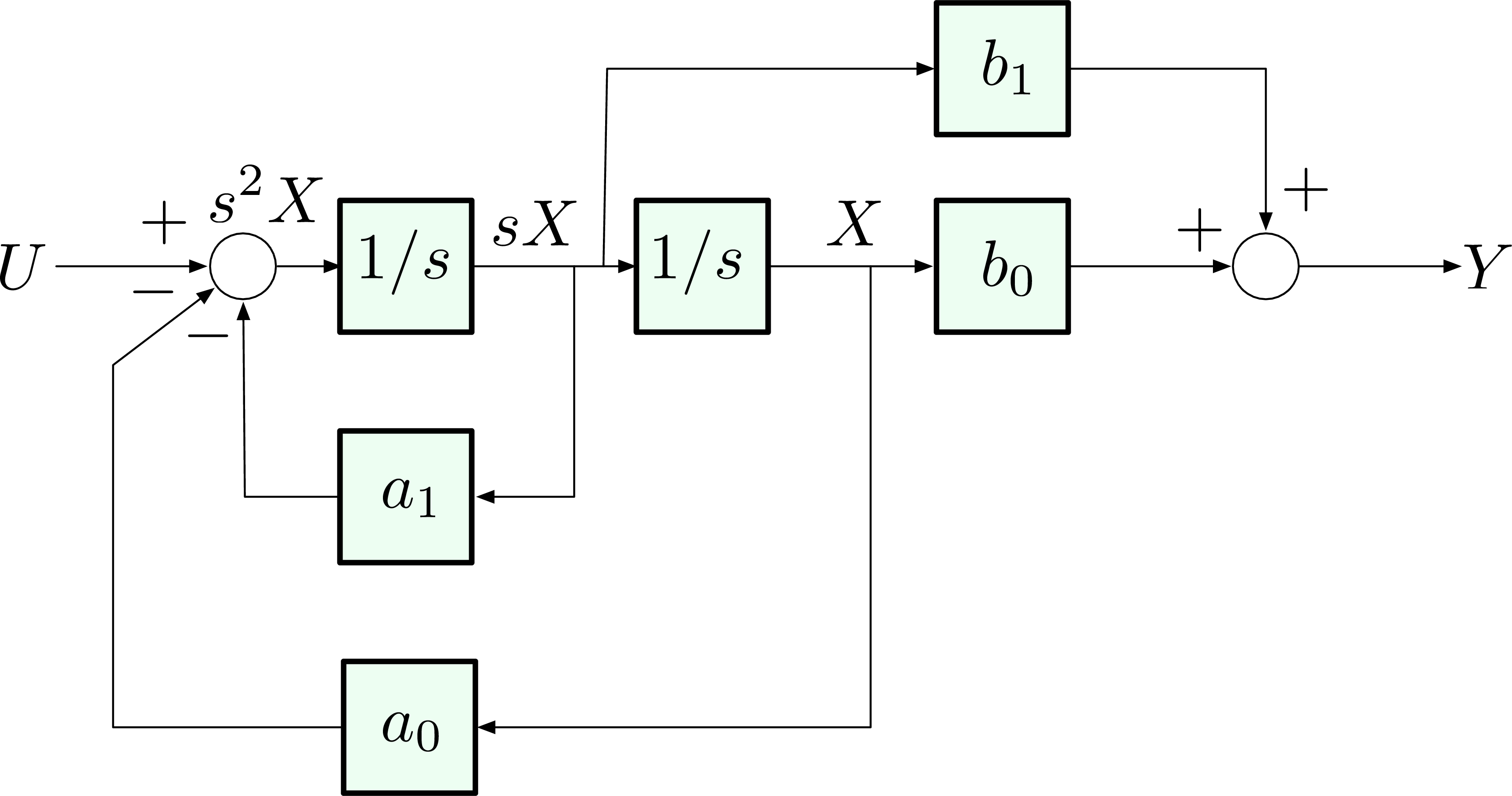
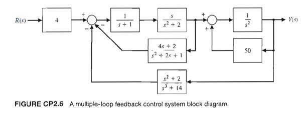
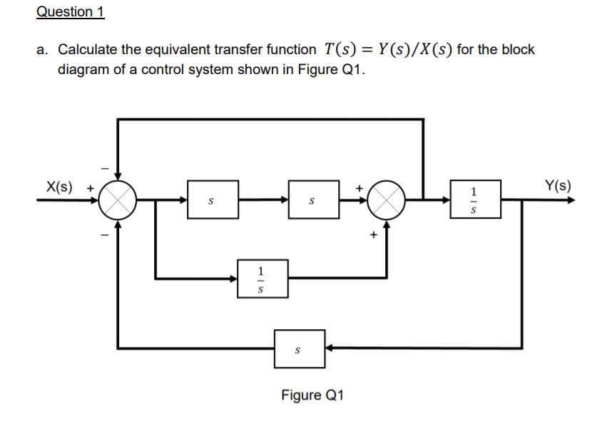
Derive your closed loop transfer function given a block diagram
G(s) – Forward path transfer function. H(s) – Feed back path transfer function. Block diagram reduction technique . Because of their simplicity and versatility, block diagrams are often used by control engineers to describe all types of systems. A block diagram can be used simply to represent the composition and interconnection of a system.
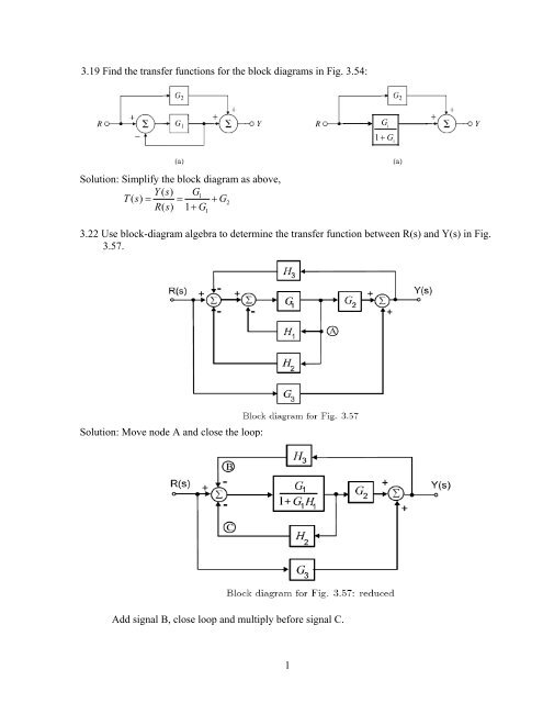
3.19 Find the transfer functions for the block diagrams in Fig. 3.54: Solution: Simplify the block diagram as above, 1 2 1 () 1 Ys G Ts G Rs G == + + 3.22 Use block-diagram algebra to determine the transfer function between R(s) and Y(s) in Fig. 3.57. Solution: Move node A and close the loop: Add signal B, close loop and multiply before signal.
As a block diagram we can represent the system by F (s) W(s) X (s) Fig. 1. Block diagram for a system with transfer function W(s). Sometimes we write the formula for the transfer function in the box representing the system. For the above example this would look like F (s) 1 ms2 + bs+ k X (s) Fig. 2. Block diagram giving the formula for the.
160 BLOCK DIAGRAM ALGEBRA AND TRANSFER FUNCTIONS OF SYSTEMS [CHAP. 7 Let the - 1 block be absorbed into the summing point: Step 4c Step 5: By Equation (7.3), the output C, due to input U is C, = [G2/(1 + G1G2)]U. The total output is C=C,+C,= [ ~ 1 +G2G2] [ A] [ A] IGIR + 7.8 REDUCTION OF COMPLICATED BLOCK DIAGRAMS The block diagram of a practical feedback control system is often quite complicated.
The block diagram of Figure 3-44 can be modified to that shown in Figure 3-45(a). Eliminating the minor feedforward path, we obtain Figure 3-45(b), which can be simplified to that shown in Figure 3--5(c).The transfer function C(s)/R(s) is thus given by
Block diagram is a pictorial representation of a control system showing inter-relation between the transfer function of various components. The block diagram is obtained after obtaining the differential and transfer function of all components of a control system. Figure 2.1 shows an element of the block diagram. The arrowhead pointing toward.
Step 1 − Find the transfer function of block diagram by considering one input at a time and make the remaining inputs as zero. Step 2 − Repeat step 1 for remaining inputs. Step 3 − Get the overall transfer function by adding all those transfer functions. The block diagram reduction process takes more time for complicated systems.
Figure 4: Block diagram of a closed-loop system with a feedback element. BLOCK DIAGRAM SIMPLIFICATIONS Figure 5: Cascade (Series) Connections. Consider a system whose closed-loop transfer function is H(s) = K s(s2 +s+1)(s+2)+K. (18) The characteristic equation is s4 +3s3 +3s2 +2s4 +K = 0. (19) The Routh array is s4 1 3 K s3 3 2 0 s2 7/3 K ...
Transcribed image text: 3(a) Figure 5 shows the block diagram model of a dynamic system. Determine the equivalent transfer function of the system that correlates the output, C, to the input R. (5 marks) R(S) C(s) G G2 H H2 Figure 5: A block diagram.
K. Webb ESE 499 3 Block Diagrams In the introductory section we saw examples of block diagrams to represent systems, e.g.: Block diagrams consist of Blocks - these represent subsystems - typically modeled by, and labeled with, a transfer function Signals - inputs and outputs of blocks - signal direction indicated by arrows - could be voltage, velocity, force, etc.
Draw block diagram from the following equations. Q Motor position transfer function with speed changer. Note: multiplication by s. 10/28/2015 12 DC MOTOR TRANSFER FUNCTION EXAMPLE 23 x Example 14-2: A permanent magnet dc motor has the following specifications. Maximum speed = 500 rad/sec













0 Response to "39 Block Diagram Transfer Function"
Post a Comment