39 Beuler Relay Wiring Diagram
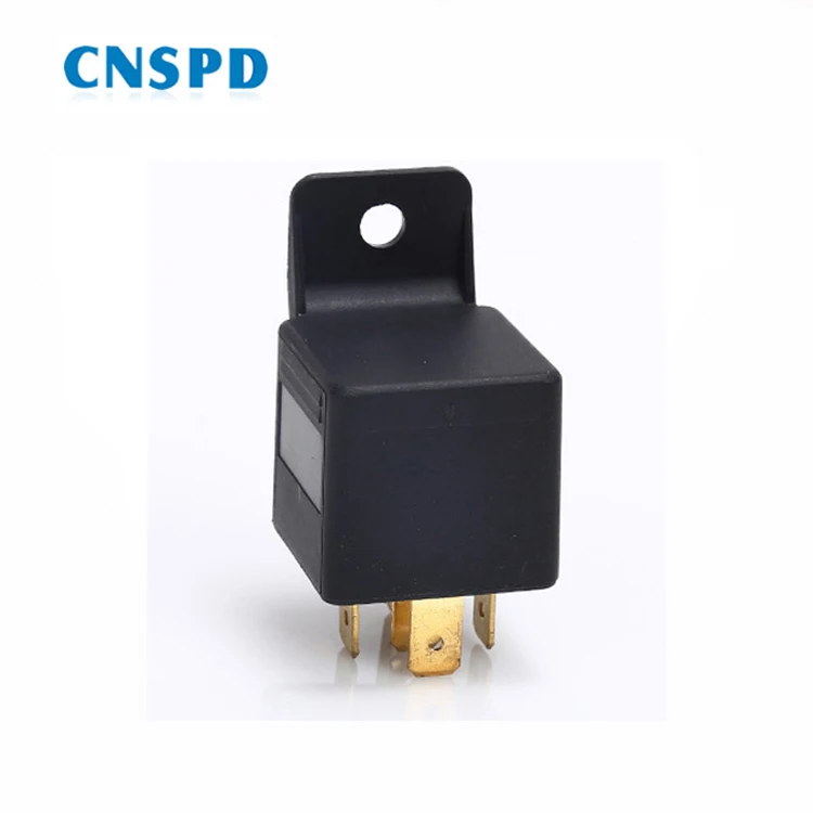
Beuler 5083 12 VDC Automotive 5-Pin Relay SPDT 40/60A with Plastic tab and Negative spike protection. The Beuler 5083 12V, 40A/60A relay is the most popular relay in automotive sound and security installations. It easily switches 40 amps of current and peaks of 60 amps with minimal draw on the coil of 147 milliamps @ 12Vdc. Beuler relay wiring diagram full hd version wiring diagram. How wire a 2jz ge ecu and immobilizer 1jzgte vvti jx100 ecu plugs c86. Source: schematron . Map sensor (all jz map sensors are interchangeable). Source: wilbo666.pbworks . Apexi safc 1988 supra na wiring diagram.
Relay Latching Circuit using Push Button. We connect relay and push button as per figure. When we press push button, supply goes to relay A1 point and relay gets ON and its contact changes, but when we release push button supply cutoffs and relay gets off. But relay not do not fall in hold. So here we think what we shall do for relay to hold.

Beuler relay wiring diagram
- im Elektroforum - - Elektronik und Elektro. Forum Themen Beiträge Letzter Beitrag; Guten Tag lieber Besucher! Herzlich willkommen im Forum für Elektro und Elektronik. Beuler relay wiring diagram when a machine or engine must control a circuit using a lower power signal or when several circuits must be controlled using one uniform signal an electrical. This is a direct replacement for any 12 volt normally closed bosch relay. Beuler BUM Waterproof 12 VDC Automotive 5-Pin Relay - Connection diagram The Beuler BUM relay is unique being that it is a waterproof 12 volt. There are a few questions in there, so I will try to address them all. The Bueler Time Delay relays are unlike the vast majority of other relays you. Relay Wiring Diagram.
Beuler relay wiring diagram. Beuler Relay Wiring Diagram. When a machine or engine must control a circuit using a lower-power signal, or when several circuits must be controlled using one uniform signal, an electrical. Ecobee3 Wiring Diagram Beuler Relay Wiring Diagram Inspirationa Ecobee Wiring Diagram was upload at May 1, at pm by admin, and This. Universal Beuler™ Relay with Tab by Accele®. Waterproof 40/60 Amp SPDT, Negative spike suppression Built-in. This top-grade product is expertly made in compliance with stringent industry standards to offer a fusion of a well-balanced design and high level of craftsmanship. Relay— will If 12 volt equipment will not operate from RV battery, check wiring MODELS , , , , and contains these standard.. PIC #2: The schematic above is the battery charger part of the power converter. Magnetek Converter Information The lower power supply portion can then be removed by taking out 4 more screws and Wiring Diagram 1. Beuler BUM Waterproof 12 VDC Automotive 5-Pin Relay - Connection diagram The Beuler BUM relay is unique being that it is a waterproof 12 volt. There are a few questions in there, so I will try to address them all. The Bueler Time Delay relays are unlike the vast majority of other relays you. Relay Wiring Diagram.
The Q relay family of ‘vital’ relays are commensurate to SIL 4. CONTACT RATINGS Standard Safety Contacts (Sig-Sil) Continuous current : 4 A dc. Switching current: 12 V dc 24 W lamp load or 3 x BR.930 relays rated at 3 W each. Note: The Q-Relay contact switching capability greatly exceeds this minimum BR. spec. load Enphase Q Relay Installation Guide Learn how to install the Enphase Q Relay galvanic disconnection device. Download. Join discussions on this topic. Visit the Enphase Community. Was this helpful? * Yes. No . Please help us improve. Email . An Enphase team member may follow up with you about your feedback. Beuler 5086E Mechanical DPDT 12V Latching Relay. Features: Mechanical latching relay. 16 amp 12 Vdc rated contacts. Dual DPDT micro switches - Dual pole dual throw. Momentary 12 Vdc rated solenoid. Power consumption @ 12Vdc 500 mA momentary. Compatible with most insulated and non insulated terminals. Ecobee3 Wiring Diagram. installation guide ecobee ecobee3 works with most centralized installation guide if you need help with the wiring refer to the reference diagrams at the back of this hacking the ecobee3 for wiring success medium i recently purchase an ecobee3 thermostat this is a brief story about why i went with it and the issues i had wiring it up so this is the question
The new low 1volt (1k Ohm) trigger voltage gives installers many new uses including stopping "amp pop" noises and even detecting an LED turning on! Features: Standard automotive style relay Delay OFF - Adjustable time from 2 sec. to 3 min. with internal potentiometer Internal green LED indicates when relay is on SPDT - Single Pole Dual Throw. Beuler Relay Wiring Diagram. Beuler relay model number bu 5083 0000 rated at 12 volts 40 60 amps normally closed. Beüler bu 5083 0000 40 60 amp 12 volt rela…. by Tora Sudiro. Load More. That is All. Beüler BU-5083-0000 - 40/60 Amp 12 Volt Relay with Tab, "Form C" SPDT. Beüler BU-5083-0000 40/60 Amp 12 Volt Relay with Tab "Form C" SPDT "RoHS" Compliant. Request a Quote. Categories: Beüler Automotive Relays, Commercial Grade Monitor Accessories, Commercial Grade Monitors & Open Frame Modules, LCD Monitors. Beuler BU-509TD 12 VDC Automotive 5-Pin SPDT Time Delay Relay with adjustable timingDelay-Offhttps://www.qualitymobilevideo /bu509td.html?utm_source=YouTu...
switch very quickly. The fan draws 30+amps and you need to use #10 wire on the fan power and ground wiring. If you are good with electrical stuff (90% of the people here aren't), build your own controller. The numbers on the diagram (#86, #87, etc) refer to the numbers on the bottom of a typical automotive relay.
Beuler relay wiring diagram when a machine or engine must control a circuit using a lower power signal or when several circuits must be controlled using one uniform signal an electrical. This is a direct replacement for any 12 volt normally closed bosch relay.
The socket is manufactured with 14 gauge wire leads, and the ISO relay. features a mounting bracket. Socket and relay complete. Molded base 5-pole socket. ISO relay features a mounting bracket for easy installation. 14 gauge, 12" wire leads on 30, 87 & 87A terminals. 20 gauge, 12" wire leads on 85 & 86 terminals. 40/60 amp; 12 volts DC.
Jul 12, 2020 · PSO2 NA Crafted Saiki Units VS Circuray/Union Units. How is delivery date calculated in po sap. 4m+ up to 9m DPS in 20 seconds ️ Episode 1-4 Story Computer Science, Economics, and Data Science major Marla Evelyn Odell has been named a 2021 Marshall Scholar. Mercury outboard starter solenoid wiring diagram.
high and low HID wiring help. June 18th, 2007, 06:11 AM. Today i decided to plug my old HID kit with a new set of bulbs for the high beam But there is something weird going on and i'm not sure how to fix it. I have a H4 setup for low/high, and also a separate high beam which uses 9005. For the H4, i used two diodes so that my HID will turn on.
The Type F timers are not compatible with 2-wire AC input sensors. A hard contact relay (i.e., general purpose relay) must be interposed. Replacements Output Relays Class 9998 Type TR1 used for the Class 9050 Type FT timer only. Enclosure Separately packed NEMA Type 1 sheet steel enclosure. Class 9991 Type UE7. Repeat Accuracy: ± 1% plus ±
These Wiring Diagrams will help you wire up your Nitrous System or Nitrous Accessory. Includes Nitrous Purge, Nitrous Bottle Heater, and Dedicated Fuel System. Your #1 Source for everything Nitrous. Dealer Locator Account. Toggle navigation 254-848-4300 Speak with a Nitrous Expert M-F 8:30am - 5:30pm CST Call or Text Today!.
- im Elektroforum - - Elektronik und Elektro. Forum Themen Beiträge Letzter Beitrag; Guten Tag lieber Besucher! Herzlich willkommen im Forum für Elektro und Elektronik.
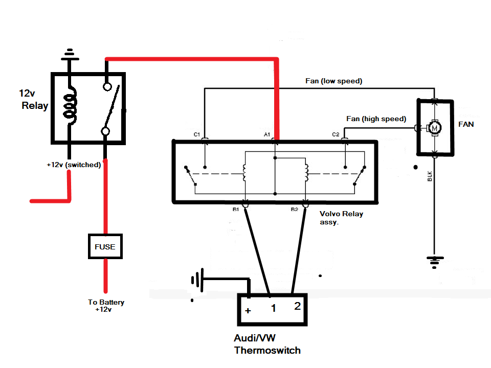
Relay Wiring Diagram. A relay is typically used to control a component that draws high amperage. The relay allows full power to the component without needing a switch that can carry the amps. The switch only controls the relay. The relay then provides a direct connection to the battery. It should be noted that either the power (86) or ground.
40/60 Amp Relay Diagram #2 Control Module (Wiring Continues on reverse side) Radiator Push-in Radiator Probe Push-in Radiator Probe Water Inlet Water Outlet Diagram #3 Push-in Radiator Probe Cross-flow Radiator Down-flow Radiator This unit is designed to control up to 2 electric fans with a combined
85 - Carrier or Pilot-Wire Receiver Relay 86 - Lockout Relay 87 - Differential Protective Relay 89 - Line Switch 90 - Regulating Device. Basics 15 Wiring (or Connection) Diagram : Basics 16 Wiring (or Connection) Diagram : Basics 17 Tray & Conduit Layout Drawing :
This wire (gray in our kit) supplies the ground signal to trigger the relay. The orange wire on the relay should see a 12 volt signal when the ignition switch is turned on. The other two wires on the relay are the meat and potatoes of the system, with the yellow wire connecting to the battery along with the supplied fuse mounted within 12.
Beuler relay, model number BU-5083-0000, rated at 12 volts 40/60 amps, normally closed. General Purpose Relay, used on most truck mounts with a 12 volt relay. This is a direct replacement for any 12 volt normally closed Bosch relay.
SPST Relay (Single Pole Single Throw Relay) an electromagnetic switch, consist of a coil (terminals 85 & 86), 1 common terminal (30), and one normally open terminal (87).It does not have a normally closed terminal like the SPDT relay, but may be used in place of SPDT relays in all diagrams shown on this site where terminal 87a is not used.
Beüler BU-5084-0000 - Waterproof 40/60 Amp 12 Volt Relay with Tab "Form C" SPDT. Waterproof 40/60 Amp 12 Volt Relay with Tab "Form C" SPDT "RoHS" Compliant. Request a Quote. Categories: Beüler Automotive Relays, Commercial Grade Monitor Accessories, Commercial Grade Monitors & Open Frame Modules, LCD Monitors.
Beuler Bu509td Time Delay Relay - Hello friend Wire Or Wired, In the article that you read this time with the title Beuler Bu509td Time Delay Relay, we have prepared this article well for you to read and take information in it. hopefully the post content Article bu509td, Article delay, Article relay, Article time, what we write can make you understand.Happy reading.
Sensors, Switches and Relays Relays and Timers General Purpose Relays #BU-5083-0000. CBC EXTRA VALUE PRODUCT #BU-5083-0000 Relay, General Purpose; 60A; SPST; 12V Coil SKU # 40100491284 Set Required Date Required by: (edit) Qty. Please enter a valid quantity Unit of Sale.
Iac Ecu 2001 Crv Wiring Diagram; Hp Pavilion P2-1033w Wiring Diagram; Kubota L2550 Parts Diagram; Beuler Relay Wiring Diagram; Kahtec Lane Changer Wiring Diagram; Hadley Power Mirror Wiring Diagram; Wiring Diagram For Bose Radio In 2005 Gmc Envoy Denali; Wiring Diagram For Lyons Store Fixtures; Ibanez Rg Hsh Wiring Diagram Rg270 With Wilkinson.
Beuler bum waterproof 12 vdc automotive 5 pin relay connection diagram the beuler bum relay is unique being that it is a waterproof 12 volt. Make offer 2 beuler 40 60a waterproof dual 5 pin relay panel 12 interconnecting socket hat903csdc24 hasco electromechanical relay spdt 40a open 30a closed 24vdc new au 15 87.
Cub Cadet Z Force 44 Belt Diagram; Bv9386nv Wiring Diagram; Emg Emg-pj Active Bass Pickup Set Black Wiring Diagram; Rs485 Half Duplex Wiring Diagram; Msd Streetfire 5520 Wiring Diagram; Raritan Crown Head Parts Diagram; Beuler Relay Wiring Diagram; Wiring Diagram For Worx 780 Lawn Mower Battery Pack; Recent Comments. Roger F. on Xbox 360.


0 Response to "39 Beuler Relay Wiring Diagram"
Post a Comment