39 3 Phase Wind Turbine Wiring Diagram
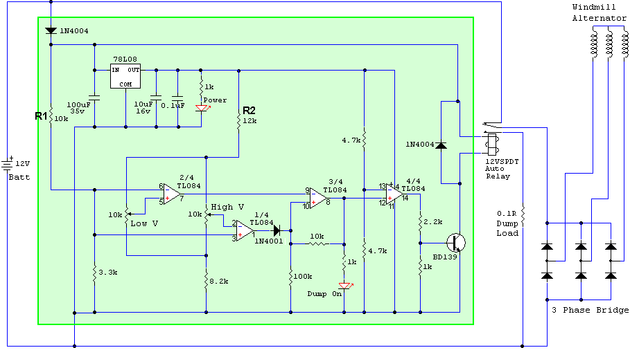
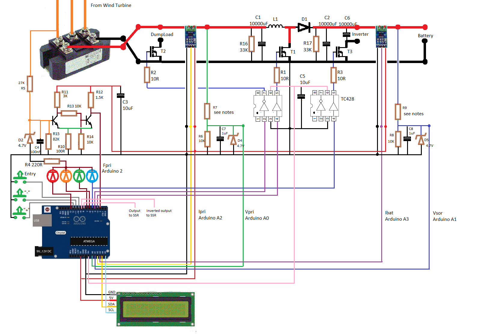
Wind Turbine Generator 3 Phase Wiring Diagram As Well Wiring Ac587 Wind Amp Solar Wiring Diagrams Digital Resources 038b41a 3 Wire Diagram Wiring Resources Share this post. 0 Response to "Wind Turbine Generator 3 Phase Wiring Diagram" Post a Comment. Note: Only a member of this blog may post a comment. A wind turbine controller protects your battery bank from over charging, applies breaking loads to limit wind turbine over speeds due to high winds or light loading, and most often convert AC power generated by wind turbine 3-phase alternators to DC power used by all battery banks.
The alternator was actually a three phase star configuration motor which was rewired to a half series half parallel 3 phase delta configuration alternator with 42 poles. This gave us an alternator with the power we wanted at a lower wind speed and RPM Blade profile design to suit alternator
3 phase wind turbine wiring diagram
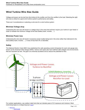
investigation can be shown in Figure 1. The three-phase alternator is connected to a three-phase rectifier, the output of which is connected to a battery bank. In the conventional system, there is no active control used to adjust the energy produced by the wind turbine; therefore, the power flow to battery is dictated solely by the wind Three phase systems are extremely common in industrial and commercial settings. They can also be found in large residential complexes and appliances requiring a large amount of power. Although these systems may seem intimidating at first, a walkthrough on 3 phase wiring for dummies will help clarify the whole situation. Different regions may use different voltages, where R was the radius of the wind turbine rotor. A typical power versus wind speed characteristic of the wind turbine is illustrated in Fig. 3. Wind Turbine Output Wind Speed (m/s) 5 7.5 10 12.5 15 17.5 20 Power (kW) 0 50 100 150 200 250 300 Fig. 3. A typical wind turbine output versus wind speed. Because this turbine was constant pitch, the.
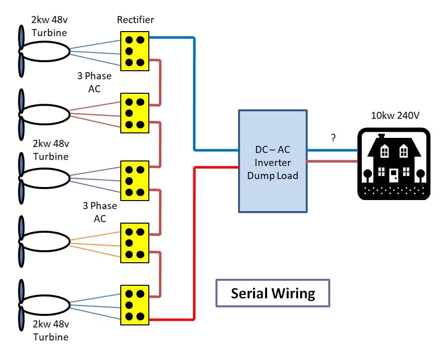
3 phase wind turbine wiring diagram. 3-Phase Wind Turbine (not included) 3-Phase Wind Turbine (not included) 3-Phase Wind Turbine (not included) 3-Phase Wind Turbine (not included) 3-Phase Wind Turbine (not. When using a charge controller follow its wiring diagram from turbine(s) to batteries. Mount rectifier near batteries (but out of reach of children) to keep DC wires short... The rpm, voltage, and current of the three-phase alternator varies with wind speed. There are three cables (conductors) between the wind turbine’s alternator and the diode bridge. There are two conductors from the diode bridge to the batteries. The conductors are #8 AWG with an AC resistance of 0.78 Ohms/1000 feet. Three-phase 4 wire system is most commonly used connection that consists of three phase conductors and one neutral conductor. In this three phase wiring, lighting, small-appliance loads and receptacles are often connected between phase and neutral while larger equipments such as air conditioners and electric heaters are connected between two phases (i.e., phase to phase). Three Phase Three-Wire Connection (Two Wattmeter Method) Where three wires are present, two wattmeters are required to measure total power. Connect the wattmeters as shown in Figure 12. The voltage terminals of the wattmeters are connected phase to phase. Figure 12 - Three-phase, three-wire, 2 wattmeter method.
I have had lots of questions about " what wires go were" on our 3 phase wind turbines. so a quick video on hooking up a 3 phase wind turbine to the Charger C... wind turbine wiring diagram - What's Wiring Diagram? A wiring diagram is a schematic which uses abstract pictorial symbols to demonstrate all the interconnections of components in a system. Wiring diagrams comprise two things: symbols that represent the components inside the circuit, and lines that represent the connections together. 3 phase power is typically 150% more efficient than single phase in the same power range. In a single phase unit the power falls to zero three times during each cycle, in 3 phase it never drops to zero. The power delivered to the load is the same at any instant. Also, in 3 phase the conductors need only be 75% the size of conductors for single. Convert three phase power to DC output using a Bridge Rectifier. AC output wind turbines require a three phase bridge rectifier for charging a battery bank. We recommend using spade terminals or box lugs and dielectric grease for best quality connections. If playback doesn't begin shortly, try restarting your device.
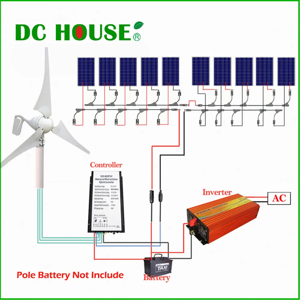
investigation can be shown in Figure 1. The three-phase alternator is connected to a three-phase rectifier, the output of which is connected to a battery bank. In the conventional system, there is no active control used to adjust the energy produced by the wind turbine; therefore, the power flow to battery is dictated solely by the wind Charge Controller Wiring Diagram for DIY Wind Turbine or Solar Panels: This diagram shows the basic setup for those who wish to build their own Wind or Solar energy project. More infomation can be found at EcoElementals.co.uk.Thanks for looking! This also is a good method to use with two or three parallel strings. If you're looking for more detailed info on battery wiring diagrams, check out our additional links below at the bottom of this page. Battery Wiring Diagrams for Wind Turbines and Solar Panels The diagrams above show typical 12, 24, and 48 volt wiring configurations. where R was the radius of the wind turbine rotor. A typical power versus wind speed characteristic of the wind turbine is illustrated in Fig. 3. Wind Turbine Output Wind Speed (m/s) 5 7.5 10 12.5 15 17.5 20 Power (kW) 0 50 100 150 200 250 300 Fig. 3. A typical wind turbine output versus wind speed. Because this turbine was constant pitch, the.
Three Phase Motor Connection STAR/DELTA Without Timer - Power & Control Diagrams. Three Phase Motor Connection Star/Delta (Y-Δ) Reverse / Forward with - Timer Power & Control Diagram. Starting & Stopping of 3-Phase Motor from more than One Place Power & Control diagrams. Control 3-Phase Motor from more than Two buttons - Power & Control.
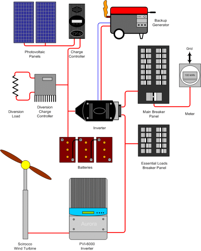
The image above shows the recommended wiring diagram for a 3 phase wind turbine or water hydro. Along with multiple solar panels wired in parallel, terminated via a standard A/C sub panel. Here is a very similar diagram as found on page 6; however, we are adding multiple solar panels and discussing the use of power distribution panels.
This item: Stop Switch for Wind Turbine Generators. $22.98. In Stock. Ships from and sold by WindyNation. Renogy 100 Watt 12 Volt Monocrystalline Solar Panel, Compact Design 42.4 X 20.0 X 1.38 in, High Efficiency Module PV Power for Battery Charging Boat, Caravan, RV and Any Other Off Grid Applications. $93.10.
How to build a wind turbine 12 volt 3 phase fisher & paykel smartdrive stepper motor. Diagram] turbine wind generator wiring diagram 3 full version hd quality diagram 3. Diagram] turbine wind generator wiring diagram 3 full version hd quality diagram 3. Small wind turbine for home. Wind turbine class k08 delta. Wind turbine wire size guide.
Before installing the Stop Switch ensure the turbine is not rotating and generating voltage. Risk of electrical shock. 3 Phase cables from the wind turbine generator 3 Phase cables to bridge rectifier The Stop Switch operates by shorting the turbine generator. Only use this switch with a Futurenergy 1 KW wind turbine and a Futurenergy bridge.
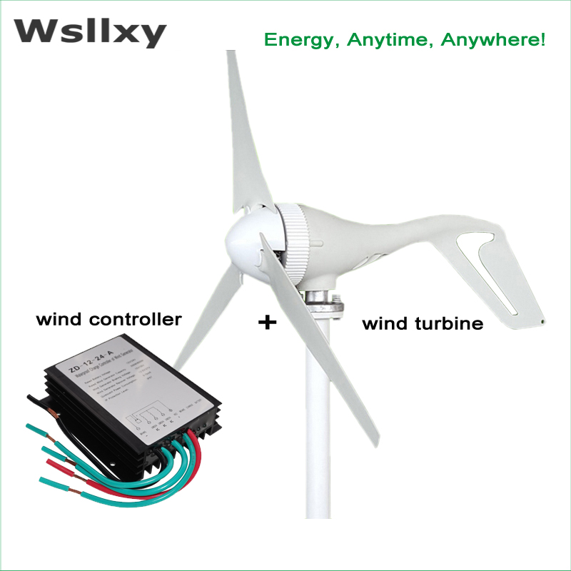
5. The wind turbine terminal can be connected to the three wires of the wind turbine in turn. If it is a DC fan or a single-phase fan, the fan wiring can be arbitrarily connected to two of the three terminals. 6. ATO wind turbine charge controller is compatible with three-phase, single-phase and DC fans. Tips:
I'm trying to use the Arduino Duemilanove to measure the voltage output of a wind turbine experiment kit, and I'm having trouble getting the right reading for the voltage. I think it's the way I'm currently reading the values from the turbine kit. The 3 phase AC output from the turbine is fed as input to an AC to DC rectifier with a single POS end and a single NEG end.
single-phase wiring diagrams always use wiring diagram supplied on motor nameplate. w2 cj2 ui vi wi w2 cj2 ui vi wi a cow voltage y high voltage z t4 til t12 10 til t4 t5 ali l2 t12 ti-blu t2-wht t3 t4-yel t5-blk t6-gry t7-pnk t8-red t9-brk red tio-curry tii-grn t12-vlt z t4 til t12
3 phase use in small wind turbine alternators. A common question we continue to get is about the 3 phase AC in the wind turbines and permanent magnet alternators and generators we use. The 3 phase alternator is the basic nature of many of the alternators and generators on the market.
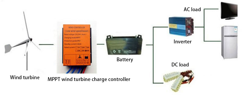
wind turbine connection diagram.Wind energy is one of the best renewable energy. In this diagram, you can store the generated electrical energy in the batter...
Three phase systems are extremely common in industrial and commercial settings. They can also be found in large residential complexes and appliances requiring a large amount of power. Although these systems may seem intimidating at first, a walkthrough on 3 phase wiring for dummies will help clarify the whole situation. Different regions may use different voltages,
The first step in actual rewinding is Coil Making; that is, creating new coils from new magnet wire and other materials. The primary objectives of Coil Making are recognizing the materials, tools and equipment needed; and how to make random wound coils to be installed into a three-phase stator core.
3-phase brake switch charge controller with LED volt meter relay heavy duty battery cables and rectifier for 3-phase output wind turbine connection You can also attach additional DC wind turbines and solar panels to the board. Assembled and quality checked by Missouri Wind and Solar in Seymour, Missouri.
STAR-DELTA Starter Without Timer for 3 Phase induction motor. Power, Control & Wiring Diagram of Star-Delta Starter. R , Y, B = Red, Yellow, Blue ( 3 Phase Lines)C.B = General Circuit BreakerMain = Mai SupplyY = StarΔ = DeltaC1, C2, C3 = Contatcors (Power Diagram)O/L = Over Load RelayNO = Normally OpenNC = Normally Closed K1 = Contactor (Contactor coil) K1/NO = Contactor Holding Coil.
"THE ONLY REASON YOU SHOULD EVER USE THREE PHASE IS TO RUN OR OPERATE AN INVERTER, TRANSFORMER OR OTHER POWER DEVICE THAT SPECIFICALLY REQUIRES 3-PHASE POWER INPUT" A. Wire Breakage I would NOT recommend the 3 phase method since you will have 3 small wires twisting in the pole and this is going to cause an electrical failure sooner or later.
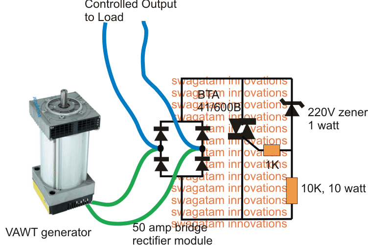
The principle of operation is based on a traditional motor generator concept where a permanent magnet type motor's spindle is integrated with a turbine or propeller mechanism for the required harnessing of wind power. As may be seen in the above diagram, the employed propeller or the turbine structure looks different.
Three phase wind turbine wiring diagrams. Page 6. Click on an item above for more specific information. The image above shows the recommended wiring diagram for a 3 phase wind turbine or water hydro. We are asked daily -- How do I connect a 3 phase A/C wind turbine to a D/C battery bank (or charge controller?)
3.1 SYSTEM WIRING DIAGRAMS Before wiring your Nature Power Wind Turbine it is important to understand how your existing system is wired and how the wind turbines interior controller operates. Nature Power recommends to connect the turbine directly to the battery bank through the wind generator controller, to its own set of battery posts.










0 Response to "39 3 Phase Wind Turbine Wiring Diagram"
Post a Comment