37 Reverse Osmosis Installation Diagram
Residential Reverse Osmosis Drinking Water System PuROMax Reverse Osmosis System has been tested to ensure it will operate correctly. The following periodic maintenance is recommended so your system will provide years of trouble-free service: Replacement parts Replacement PuROMax SF5-10 Pre-filters (sediment) every 6 mos. Installation Instructions Residential Reverse Osmosis Drinking Water System Your Reverse Osmosis System has been tested to ensure it will operate correctly. The following periodic maintenance is recommended so your system will provide years of trouble-free service: Replacement parts Replacement Pre-filter (sediment) Every 6 mos.
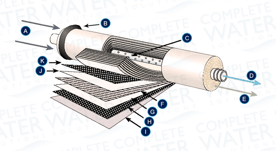
The permeate is the final and desired "product" of reverse osmosis filtration. The permeate water is sometimes referred to as pure water, or simply "product" water, and usually has 95%-99% of the dissolved salts removed from it. Concentrate. The concentrate is the undesirable water that exits the membrane element.

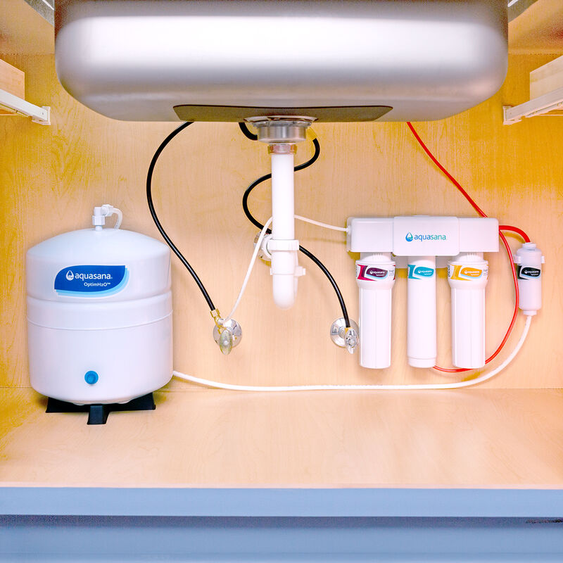
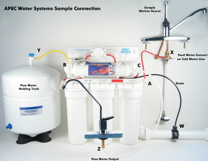
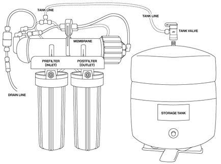
Reverse osmosis installation diagram
9. REVERSE OSMOSIS TERMS R.O.: Reverse Osmosis, this is the process of passing water through a semi-permeable membrane that allows the water molecule but not the impurities in water to pass through. This is accomplished by utilizing pressure from a pump to force the water molecules through the membrane. Reverse Osmosis Diagram. September 16, 2021 April 25, 2021 by admin. Here you will find the detailed reverse osmosis diagrams include a complete RO system diagram and its components. 9. This system has been factory wired and preset with a pressure switch at 20 - 40 psi, which is only to be used with a pressurized bladder tank. If using an atmospheric storage tank, a float switch will be required to turn the system on and off. MEMBRANE ELEMENTS LT-Series reverse osmosis systems come pre-loaded with Thin Film Composite (TFC)
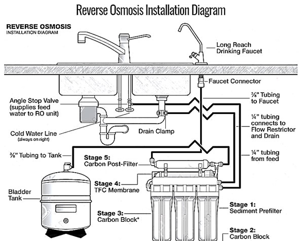
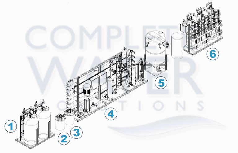
Reverse osmosis installation diagram. With this industrial reverse osmosis schematic diagram, you can learn more about the components of most RO systems from Complete Water Solutions! info@complete-water 855-787-4200 Customer Portal Tighten the drain clamps with bolts, adjusting the clamp hole with the hole in the tube. Take care not to overtighten. 3. Feed Valve Installation. In step three, we will set up the inlet feed valve that connects your reverse osmosis system into the cold-water line. First, turn off the cold and warm water supply. 5. Understanding the difference between passes and stages in a Reverse Osmosis (RO) system a. 1 stage vs 2 stage Reverse Osmosis (RO) system b. Array c. Reverse Osmosis (RO) system with a concentrate recycle d. Single Pass vs Double Pass Reverse Osmosis (RO) systems 6. Pre---treatment for Reverse Osmosis (RO) a. Fouling b. Scaling c. Chemical. Reverse Osmosis System Components. RO Module The RO module is the main component and holds the pre-filters, membrane, and post-filter. A bracket is provided so they can be mounted under the sink or in a basement. Angle Stop Valve The angle stop valve connects to the cold water line to supply water to the RO system and provides an easy ability to shut off the water supply when servicing the unit.
The installation of an under sink RO system is a bit complicated compared to the countertop RO system but it's fairly straightforward provided you follow the installation manual provided correctly. The following is the most complete diagram of a typical reverse osmosis system. Industrial Reverse Osmosis RO Systems Diagram Engineered in USA by Pure Aqua, Inc. 1- Raw water tank 2- Feed/back wash pump 3- Prechlorination 4- Automatic multimedia filter 5- Dechlorination 6- Antiscalant 7- Reverse osmosis system 8- Post pH 9-Post chlorination 10- Product water tank Home Master® Reverse Osmosis System—Owners Manual Installing The Home Master® Reverse Osmosis System 1. Mount RO Faucet* 1. Use existing spray hose hole, or drill 1/2" hole in sink top. See page 3. 2. Slide small rubber washer onto faucet shank, then metal escutcheon plate. 3. Slide rubber washer onto faucet shank. 4. The.gov means it's official. Federal government websites often end in .gov or .mil. Before sharing sensitive information, make sure you're on a federal government site.
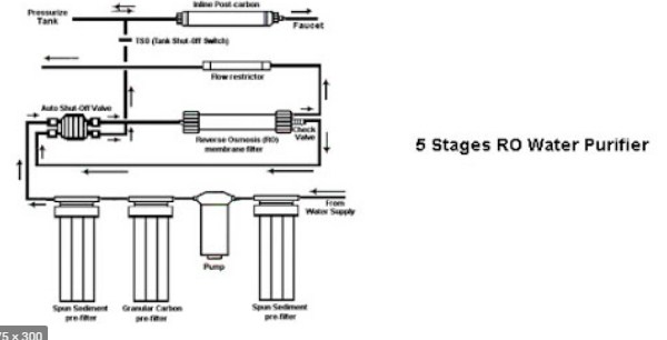
Reverse Osmosis - Installation Diagram Stage 1: Sediment Prefilter - Water travels from the source through the Sediment Prefilter. Stage 2: Carbon Block - Water then travels from the Carbon Block filters. Stage 3: Carbon Block (only available on 5 stage systems) - Stage 4: TFC Membrane - Stage 5: Carbon Post-Filter - Stage 6: Long Reach Drinking Faucet - Drink your freshly purified water! This procedure is intended to clean out your Reverse Osmosis System so the water you get will be pure and healthy. This process will take 12 hours. Please do not drink any water from your Reverse Osmosis Filter System until the System Start-Up has been completed. Allow pressure to build for 10 minutes. With the Reverse Osmosis Faucet Reverse Osmosis Diagram. September 16, 2021 April 25, 2021 by admin. Here you will find the detailed reverse osmosis diagrams include a complete RO system diagram and its components. About the system Reverse Osmosis process is a separation process. Tap water enters the system, and it is separated at the 4 th stage membrane filter. One side would go to the storage tank (purified water); the other side carrying all the minerals is purged to the drain. The ratio of purified water to drain water is 1:3.
9. This system has been factory wired and preset with a pressure switch at 20 - 40 psi, which is only to be used with a pressurized bladder tank. If using an atmospheric storage tank, a float switch will be required to turn the system on and off. MEMBRANE ELEMENTS LT-Series reverse osmosis systems come pre-loaded with Thin Film Composite (TFC)
Reverse Osmosis system and the refrigerator. WARNING: Discard all unused parts and packaging material after installation. Small parts remaining after the installation could be a choke hazard. Sanitize upon installation of the Reverse Osmosis system and after servicing inner parts, including replacement of prefilter, postfilter and Reverse
Thank you for choosing the iSpring Reverse Osmosis Water Filtration System. It was built from quality components, and has earned WQA GOLD SEAL certification against NSF/ANSI STANDARD 58 for performance and material safety. Please check the attached iSpring RO Systems WQA Gold Seal Certification for details. BEFORE INSTALLATION Inspect the package
How to Install a Reverse Osmosis System Step 1: Prepare for the Installation. Before you even buy a reverse osmosis system, you must be sure it'll fit underneath your kitchen sink. Use a tape measure to get measurements of your available space, then compare the figures with the dimensions of the system you're interested in.
**Special Offer Ends 4-24-17: 10% Off Our Top Rated 5 Stage Complete Home RO Water Filter System. Code: 10GXLMQ. See System here https://www.uswatersystems.c...
Reverse Osmosis System with Quick-Connect Fittings. SyStem and Faucet dIaGram 1 Insert tube 2 Push up to tube stop 3 Pull to check secure 4 Disconnecting 1. Fitting grips before it seals. Ensure tube is pushed into the tube stop. 2. Push the tube into the fitting, to the tube stop. The collet (gripper) has
Make sure there is sufficient space under the counter for installation (an area of about 17"L x 6"W x 18"H for the system, 11"D x 18"H for tank). The RO system is best installed under the kitchen sink. But if that is not feasible you can install the system
2. Basic Reverse Osmosis Plant Construction The typical reverse osmosis plant, particularly for seawater desalination as shown in Figure 1, is composed of the following facilities: Figure 1. Seawater RO desalination system flow diagram. 2.1. Feedwater Supply Facility The feedwater supply facility may include an intake port off the seacoast.
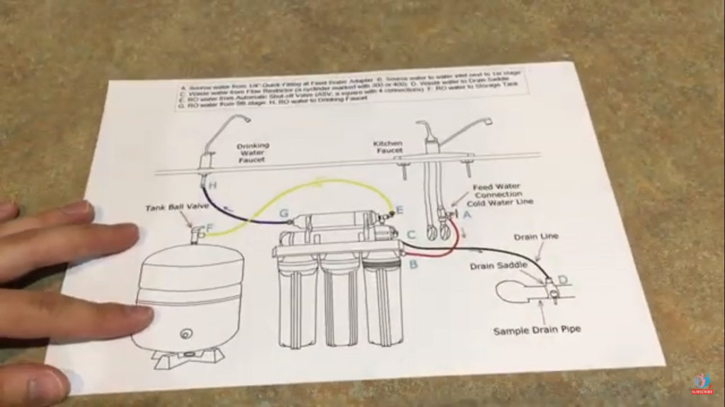
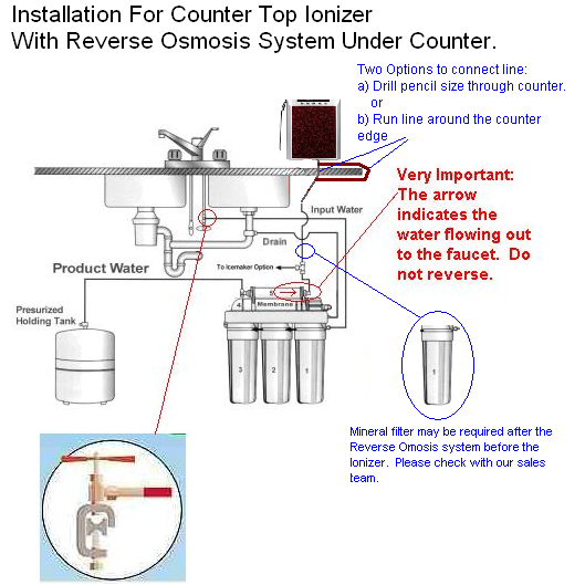
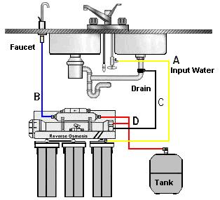
Reverse Osmosis System Installation Diagram. Courtesy of BOS. Since it can be troublesome for some people to identify different components of an RO system, we took it upon ourselves to find a diagram showing the names of all parts and how they're connected to each other.
Installation Diagram of 4 Stage Reverse Osmosis Systems. The 3 stage, 4 stage and 5 stage reverse osmosis systems install exactly the same. The only difference is the addition of a carbon water filter before the membrane on the 4 stage RO system and two of them on the 5 stage system.
An alternative is to install a separate softener just for the reverse osmosis system. it should be capable of providing continuous soft water while the reverse osmosis system is operating, or a timer cutout should be installed to shut off the reverse osmosis system during softener regeneration. Consult the factory for recommendations.
9. REVERSE OSMOSIS TERMS R.O.: Reverse Osmosis, this is the process of passing water through a semi-permeable membrane that allows the water molecule but not the impurities in water to pass through. This is accomplished by utilizing pressure from a pump to force the water molecules through the membrane.
No need to mount the RO system on the wall. The RO system can stand in the sink cabinet without mounting, this makes future filter change easy and convenient. If you prefer to mount the system to the wall, please make sure it can be taken down easily for filter replacement.
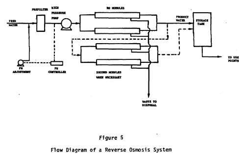
A typical reverse osmosis system is shown in the flow diagram (Figure 5) (image size 11KB). Feed water is passed through a prefilter after pH adjustment, and is pumped to the membrane modules at.
What is reverse osmosis diagram? What is a reverse osmosis system? What Is Reverse Osmosis. What is reverse osmosis short answer?: the movement of fresh water through a semipermeable membrane when pressure is applied to a solution (such as seawater) on one side of it. What is the function of reverse osmosis?













0 Response to "37 Reverse Osmosis Installation Diagram"
Post a Comment