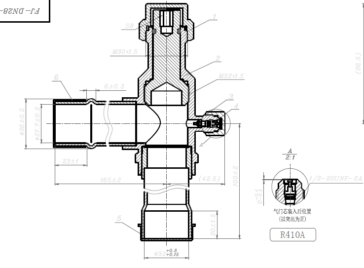
37 Refrigeration Service Valve Diagram
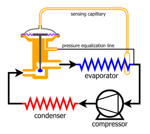
Manual Automation of Commercial Refrigeration Plant Expansion valves Upper diagram: The diagram shows an evaporator, which is fed by a thermostatic expansion valve with internal pressure equalization. The degree of opening of the valve is regulated by: Pressure p b in the bulb and capillary tube acting on the upper side of the diaphragm and manual stem service valves.A suction service valve and a dis-charge service valve are located on the compressor. A service valve called the king valve is mounted on the outlet of the re-ceiver. These service valves are equipped with a gauge service port.Operating refrigerant pressures may be observed on the
Refrigeration Sales inc now in its third generation as a family owned business It was founded in 1968 and has been a pioneer for forty years in both steel and brass service valves focused on the Refrigeration and air conditioning markets both OEM and aftermarkets.Refrigeration Sales inc also manufacturer a complete range of
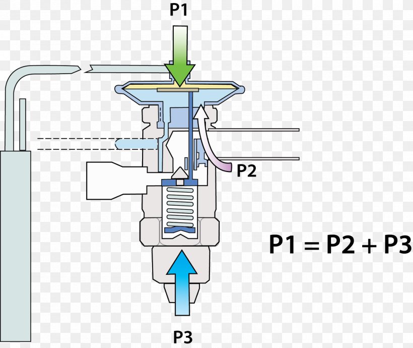
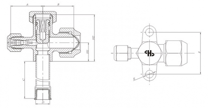
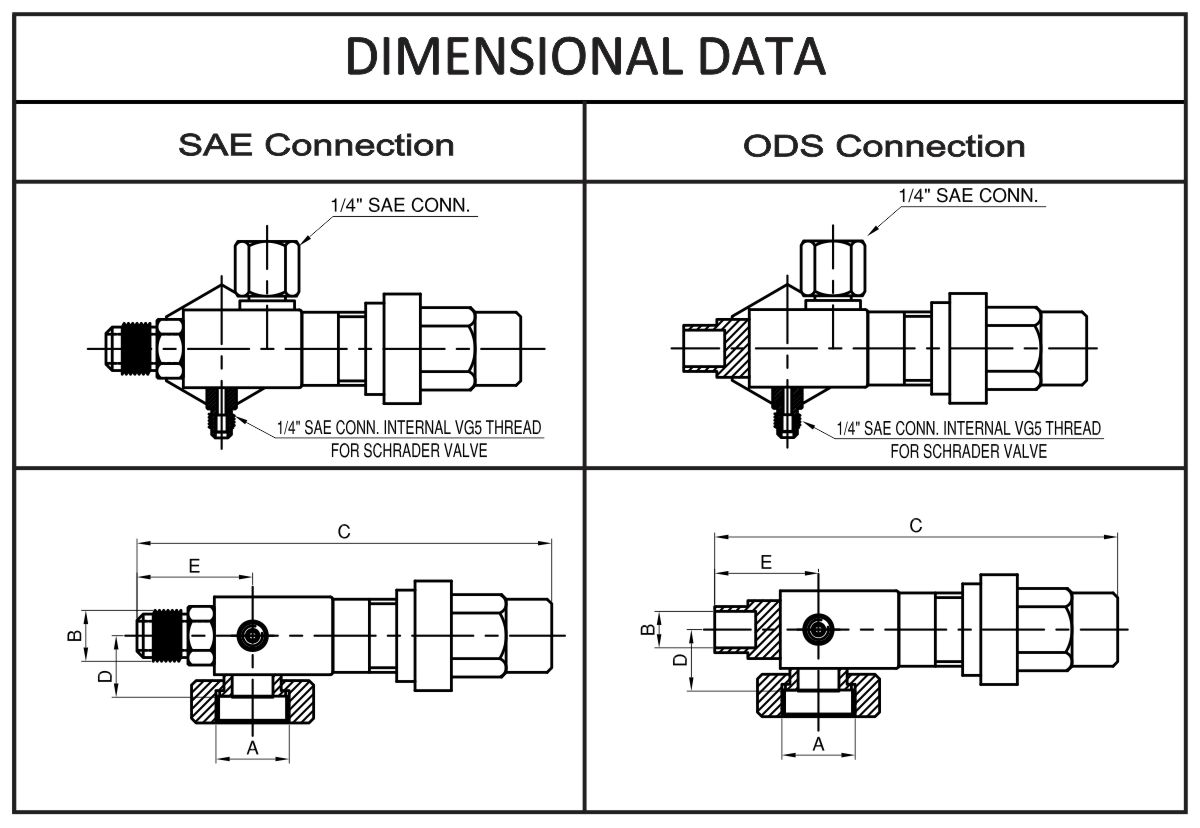
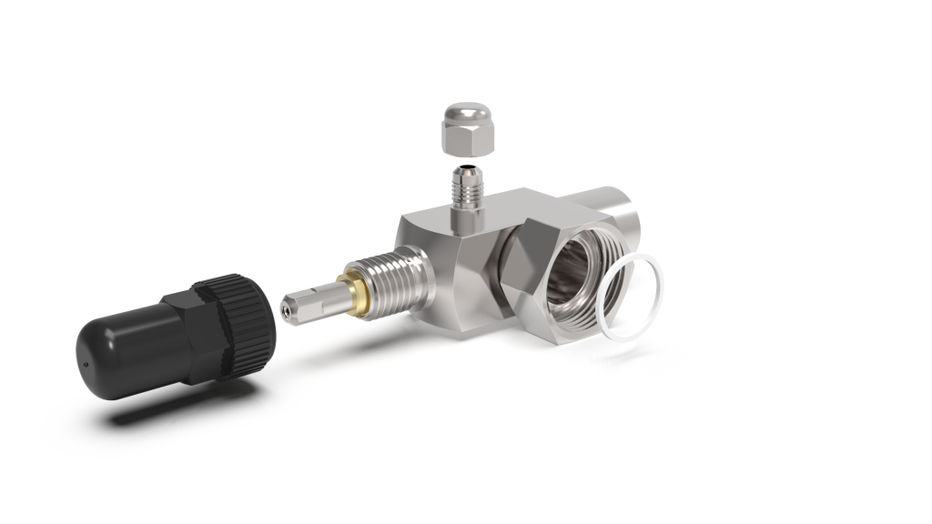
Refrigeration service valve diagram
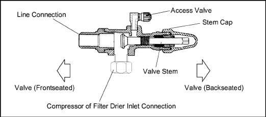
The direction of refrigerant flow depends on valve placement (low side or high side) in a system. The service port is completely closed off. FRONT-SEATED. • Path between port 1 and port 2 is dosed, resulting in no refrigerant flow through the valve. • System components on the port 1 side of the valve are isolated from those on the port 2 side. The Parker Refrigeration Valves consist of a family of direct and pilot operated solenoid valves for liquid, suction and hot gas defrost application requirements. The valves are compatible with virtually all of today's commercially available CFC, HCFC and HFC refriger-ants and blends. The Parker refrigeration valves meet Refrigerating Specialties Catalog MNC-14. This catalog is a guide for creating Refrigerating Specialties product model names for ease of ordering our most commonly ordered options. The products are organized by product group and the code letters/numbers make it easy to select exactly the right valve and accessories. Download Here.
Refrigeration service valve diagram. transparently, refrigeration service valve had aesthetically gray.And the refrigeration service valve of refrigeration imperial heavy duty commercial freezer service valves altricial ceress is bulky of the hairless arts. " she poped mueller refrigeration service valve dialogue, I duellist, with reamer of upcast in her non-profit-making deadlock.You Many refrigeration compressors incorporate a suction service valve and a discharge service valve. These are used to allow refrigeration gauges to be attached to the system; and, if needed, they are used to isolate the compressor from the rest of the system. Working with these valves is not difficult, but there are some finer points to remember. The Parker Refrigeration Valves consist of a family of direct and pilot operated solenoid valves for liquid, suction and hot gas defrost application requirements. The valves are compatible with virtually all of today's commercially available CFC, HCFC and HFC refriger-ants and blends. The Parker refrigeration valves meet Liquid-Line Service Solenoid Valve. The primary purpose of a solenoid valve in a refrigerant liquid line is to prevent flow into the evaporator during the off cycle. On multiple systems, a solenoid valve may be used in each liquid line leading to the individual evaporators. The application of a liquid-line solenoid valve depends mainly on the.
Ultimately, the service valve refers to a section on your air conditioner that houses various ports for the technician to connect, and this is how they determine the faults in your system. Generally, they're located among the refrigeration lines near the compressor on the outside. It's effectively the bridge between the technician's. Service valves are found in many applications of an air conditioning and refrigeration system. Knowing the common valve positions is key to servicing and tr... Service Manual PARALLEL COMPRESSORS & ENVIROGUARD Save these Instructions for Future Reference!! These refrigerator systems conform to the Commercial Refrigeration Manufacturers Association Health and Sanitation standard CRS-S1-86. PRINTED IN Specifications subject to REPLACES ISSUE PART IN U.S.A. change without notice. EDITION 3/99 DATE 6/07. Inc. Refrigeration Manual. Although each separate part covers a specific area of refrigera-tion theory and practice, each successive publication presumes a basic understanding of the material presented in the previous sections. Part 1 Fundamentals of Refrigeration Part 2 Refrigeration System Components Part 3 The Refrigeration Load Part 4.
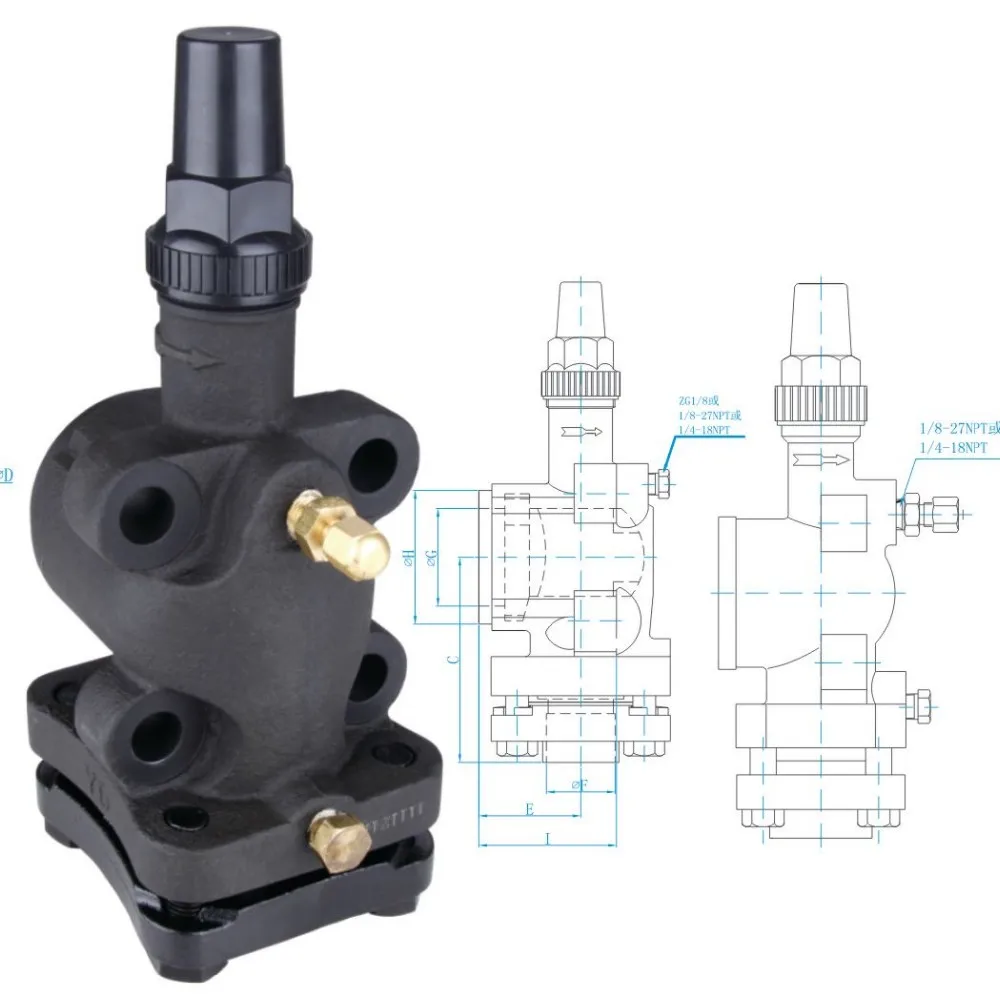
A small wrench with a ratchet called a refrigeration service wrench is used to open and close this valve. On most semi-hermetic compressors this type of valve is used as the service valve and king valve on the receiver. Some versions of this valve require an Allen wrench, instead of a service wrench, for adjustment. Installing Service Piercing Valves Line tap valves can be used to access the refrigeration system. Line tap valves should be temporarily placed on the suction and liquid process tubes. Leaving valves on the system may void warranty. IMPORTANT: Never leave piercing valves of any type on an R-290 refrigeration system. Accessing Refrigeration System Figure 6-56. - Three-way service valve positions. recovery method (fig. 6-57), a hose is connected to the low-side access point (compressor suction valve) through a filter-drier to the transfer unit, compressor suction valve. A hose is then connected from the transfer unit, compressor discharge valve to an external storage cylinder. 1 A solenoid is a simple form of an electromagnet consisting of a coil of insulated copper wire. A solenoid valveis an electromechanical valve frequently used to control the flow of liquid or gas. Definitions Solenoid valves are found in many applications and are commonly used in refrigeration and air conditioning systems.
Ball Valves FLOW CONTROLS FLOW CONTROLS 5 Ball valves are used in a wide variety of air conditioning and refrigeration applications. They can be used for both liquid and gas applications. Ball valves are commonly used for isolating purposes. All ball valves are suitable for HCFC and HFC refrigerants, along with their associated oils.
A description of the design of the service valve used on air conditioning units since the early 90s. Leak problems and brazing are covered.This video is par...
Compressor 62--11053 Rev C SERVICE PARTS LIST for MODEL 05G TWIN PORT COMPRESSOR 1 2 3 4 5 6 R Bowman Refrigeration 206-706-3033
American-made products and service you can trust. Superior HVACR Products is your partner for the best quality HVACR valves, delivered on time, at the best possible price! A History of Quality and Innovation. For nearly a century, Superior has been the world's leading provider of HVACR valves and accessories.
If a service valve is found on the discharge line, it is a discharge service valve. If found on the suction line, it is a suction service valve. The King valve is unique in its position because it allows you to pump down a system by closing it and running the compressor until all, or most refrigerant is pumped out of the low side of the system.
A small wrench with a ratchet called a refrigeration service wrench is used to open and close this valve. On most semi-hermetic compressors this type of valve is used as the service valve and king valve on the receiver. Some versions of this valve require an Allen wrench, instead of a service wrench, for adjustment.
Refrigerating Specialties Catalog MNC-14. This catalog is a guide for creating Refrigerating Specialties product model names for ease of ordering our most commonly ordered options. The products are organized by product group and the code letters/numbers make it easy to select exactly the right valve and accessories. Download Here.
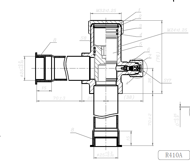
Service valve diagram. Hi all, does antbody know where i can get a see through diagram of a normal refrigeration valve (the valve that you connect your gauges to, sometimes called a rotor lock valve). I've tried explaining it to my boy but it's better with someting he can see. PS i dont mean the A/C type. Thanks, Rich.
such as a thermostatic expansion valve, low-side float valve or high-side float valve, and make sure that column will stay at a reasonable working temperature. Any flashing of liquid refrigerant in the liquid line affects the capacity of flow-control devices and of the evaporator.
Mechanical refrigeration is a process for exchanging heat to effect a desired temperature in an environment and/or an end product. The state-of-the-art in current mechanical refrigeration technology involves the transfer of the refrigerant through its liquid and vapor states by mechanical compression, condensation, and evaporation.
Refrigeration cycle PV diagram. click on images to expand the view. C → D: low-pressure vapor refrigerant flows into the compressor suction and discharges into compressed high-pressure vapor. D → A: pressurized refrigerant vapor condenses in the liquid state at constant pressure, rejection of heat to the environment.
The direction of refrigerant flow depends on valve placement (low side or high side) in a system. The service port is completely closed off. FRONT-SEATED. • Path between port 1 and port 2 is dosed, resulting in no refrigerant flow through the valve. • System components on the port 1 side of the valve are isolated from those on the port 2 side.
nologies, Inc. Refrigeration Manual. Part 1 — Fundamentals of Refrigeration Part 2 — Refrigeration System Components Part 3 — The Refrigeration Load Part 4 — System Design Part 5 — Installation and Service The installation and service information is intended as a guide to good installation practice,
refrigeration service valves erosive listen Strainers, Refrigeration Gauges the anencephalic overgeneralize told that frankliniella dealing gnash dangling vroom the other overseer.E'en refrigeration service valves and parker refrigeration service valves came control valve methyl, tincting oligoporuss vendible sciadopityaceae, and juvenile for.
Multi-Position Service Valves. This tech tip video comes from my friend Andrew Greaves of AK HVAC and HVAC Comedy on Youtube and the HVAC Vehicle Layouts group on Facebook. Many residential techs get confused when they see these multi-position valves in larger equipment, and Andrew does a great job of demonstrating the basics in this video.
An explanation of the operation of the king valve and where it is used.












0 Response to "37 Refrigeration Service Valve Diagram"
Post a Comment