37 Oil Pressure Safety Switch Wiring Diagram
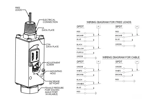
Pressure Ammeter Battery + _ + _ + _ ST ACC IGN BAT Start Switch Alternator To Magnetic Sensor, Alternator “Tach” Terminal, or Signal Generator B+ Energized to Run PB128S Stop Switch Starter S B Exciter R Fuel Valve Typical Wiring Diagram with 760A and 761APH G NO R NC SW1 SW2 B 518PH Jumper* B+ SIG GRD + _ Distributor Ignition coil Fuel. pressure safety switch in the remaining two holes. 5. Screw in the two switches and reconnect the lead to the original equipment oil pressure switch. NOTE: The pressure safety switch will normally have three terminals marked: C (common), N (normally closed), and NO (normally open). 6. Connect the fuel pump (RED lead) to the terminal marked “C”.
Just trying to figure out if this can be done. I have an oil pressure Safety Switch (LINK) installed off a Tee at the oil pressure sensor. I want to use this device to kill the fuel pump when it senses a loss of oil pressure. This switch is basically a relay that closes once oil pressure is above 3 psi (it can be wired either way NC or NO).
Oil pressure safety switch wiring diagram
20. Jun 25, 2007. #3. Re: Oil Pressure switch Diagram. see the thing is the guy had it wired to a toggle so you could hold the toggle, prime the pump and fire it up if it sat for a while. well i dont even think the starter solenoid terminal has a wire to the switch on it, and when it died in the water all of a sudden, the two wires i took off. Carter Oil Pressure Safety Switches. Carter oil pressure safety switches shut down your engine when your oil pressure drops below 7 psi, saving your engine from damage. These switches come with complete instructions and a wiring diagram. Warranty Oil Pressure Switch Wiring Diagram – wiring diagram is a simplified all right pictorial representation of an electrical circuit. It shows the components of the circuit as simplified shapes, and the gift and signal friends in the middle of the devices. A wiring diagram usually gives opinion roughly the relative point of view and understanding.
Oil pressure safety switch wiring diagram. Joined Sep 2, 2006. ·. 8,871 Posts. #2 · Jul 26, 2015. 1967 chevelle said: I'm installing an electric fuel pump and want to include in my circuit a Relay, Circuit breaker & Oil Pressure Safety Switch. I did some research online and found a wiring schematic. I have a few questions, on the Oil pressure safety Switch "I" terminal where is the. 20. Jun 25, 2007. #3. Re: Oil Pressure switch Diagram. see the thing is the guy had it wired to a toggle so you could hold the toggle, prime the pump and fire it up if it sat for a while. well i dont even think the starter solenoid terminal has a wire to the switch on it, and when it died in the water all of a sudden, the two wires i took off. Carter Oil Pressure Safety Switches. Carter oil pressure safety switches shut down your engine when your oil pressure drops below 7 psi, saving your engine from damage. These switches come with complete instructions and a wiring diagram. Warranty low oil pressure lamp brake warning switch low oil pressure switch ignition switch reverse lights & switch brake lights & switch ammeter heater fan switch + - s ta re battery gauge illumination lamps w1 w2 c1 c2 yp w yg yg b y y n b f r o m f u s e b o x overdrive on - off switch transmission interlock switches pull-in coil cut-out switch.
Click upon Set Line Hops in the SmartPanel to show or even hide line hops at crossover points. You can even change the particular size and form of your line hops. Select Show Dimensions to display the length of your wire connections or size regarding your component. Source: Oil Pressure Safety Switch Wiring Diagram. from www.moyermarineforum . 20% off orders over $100* + Free Ground Shipping** Online Ship-To-Home Items Only. Use Code: NOVSAVINGS (try the orange wire of the oil switch to the yellow wire of the relay) It appears that the oil pressure switch is a single pole double throw switch that supplies power supplies power from the starter during cranking through its red wire, and then through the ignition switch on its white wire once the engine starts. Ok, I ended up replacing the whole harness over the past 6 months and I'm now I'm back to wiring up this fuel pump. I am using a 30A bosch relay and an oil pressure safety switch, referencing these two diagrams: I've run pin 30 of the relay through a 20A fuse and back to the starter solenoid and have run pin 87 back to the fuel pump. 1.
P0868 Combination 0868 reports a low oil pressure in the secondary circuit. The cause of the problem is a jammed pump pressure reducing valve.. P1819 Code P1819 appears as a result of a short circuit in the safety switch of the transmission... im looking the complete engine wiring diagram & schematic thats color coded for my 4dr 1994 honda ... Mar 29, 2021 · master switch 2 block diagram ( left ) /28. pressure sensor pump /87. master switch 2 general layout ( left ) /29. pressure sensor winch 1 /92. master switch 2 supply (. Title: P45 Series Typical Wiring Diagrams Illustrating Use of Oil Pressure Cutout Controls Technical Bulletin Created Date: 20180323135817Z How to do wiring and testing of Danfoss oil pressure switchin airconditioning and refrigeration system. (Hindi and Urdu)
This circuit is similar to the basic wiring diagram the same except you use a different pressure switch and add a warning light that directly watches the oil pressure. The 3 Terminal pressure switch has an extra terminal that can be used exactly like the Oil Pressure warning Light. The switch actually is 2 Switches in one.
Oil Pressure Switch Wiring Diagram – wiring diagram is a simplified all right pictorial representation of an electrical circuit. It shows the components of the circuit as simplified shapes, and the gift and signal friends in the middle of the devices. A wiring diagram usually gives opinion roughly the relative point of view and understanding.
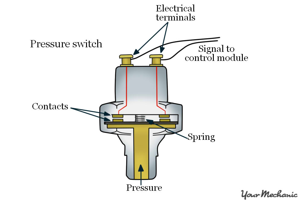
The oil pressure switch sends a signal directly to the driver's instrument panel or the engine control module. It indicates if the engine's oil pressure has fallen below a critical level of ~ 3-10 psi, depending on the engine. Gauge sending units are often variable resistors, but the sending units for the instrument panel's warning lights, like.
How to bypass safety switch on troy bilt riding mower
If the oil pressure switch trips it should not be reset or by-passed but the cause for the failure must be found prior to resetting then starting up again. NOTE: Oil pressure safety control with an approved switch is a condition of warranty ! Oil Pressure Differential Normal oil pressure is between 1.05 and 4.2 bar higher than crankcase pressure.
4. Screw a 1/8" pipe tee onto the nipple and position it in a manner to facilitate the installation of the original oil pressure switch and the new fuel pump pressure switch in the remaining two holes. 5. Screw in the two switches and reconnect the lead to the original equipment oil pressure switch. NOTE: The pump oil pressure switch will.
Nov 07, 2021 · The oil pressure is normal, at 22 psi on idle but low, at 30 psi, when running May 16, 2014 · cummins ISX15 oil pressure Discussion in 'Trucks [ Eighteen Wheelers ]' started by mitmaks, Dec 12, 2015. You could have a problem with the oil pressure sensor itself or the wiring. 435.
BMW - electrical systems - WIRING DIAGRAM. Oil pressure switch 13. Temperature transmitter 14. Diagnosis conneclion 15. Engine plug 16. Battery 17. Spark plugs... Power safety switch 15. Child safety switch 16. Window motor front left 17. Window motor front right 18. Plug for driver's door wire to window motor front left
This switch, pictured as normally closed, will OPEN when there is sufficient pressure differential. So, when we start the compressor, power is applied to V1 (or to V), and once oil pressure builds up to the 9-12 PSIG range, it will open switch PC and de-energize the heater. Now, if this switch (PC) is closed, and the control is energized (power.
A switch is ON or OFF like a oil level switch. The Oil pressure sensor is located on the top of the motor, drivers side at the rear. The voltage signal is sent to the pcm and then to the cluster to the oil pressure gauge. On your 2004 Silverado, the oil pressure sensor and the oil level switch have nothing to do with the fuel pump.
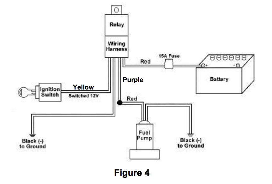
Today I tried my hand at installing a fuel pump relay and oil pressure safety switch, but didn't quite get the result I'm looking for. The fuel pump isn't supposed to run until the oil pressure sensor hits 5 psi, but right now the pump turns the second I hook the ground cable up on the battery, so obviously I've got my constant wrong, but not sure how to make it all work together.
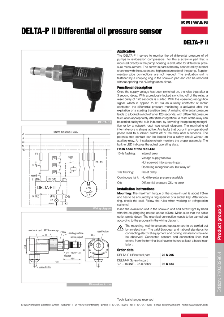
MP 54 and MP 55 oil differential pressure switches are used as safety switches to protect refrigeration compressors against low lubricating oil pressure. If the oil pressure fails, the switch will stop the compressor after a predetermined time period has elapsed. MP 54 and MP 55 are used in refrigerating systems
Jul 15, 2003. Location: Redmond, Wa, USA. Hi All, I'm getting the wiring ready for my in tank electric fuel pump. The below wiring diagram is how I am wiring it up, I added some of my own wire colors in the pic. I'm using a PS140 pressure sensor which should be the same as the below NC, C, NO. I've hit a snag where I believe I just have the NC.
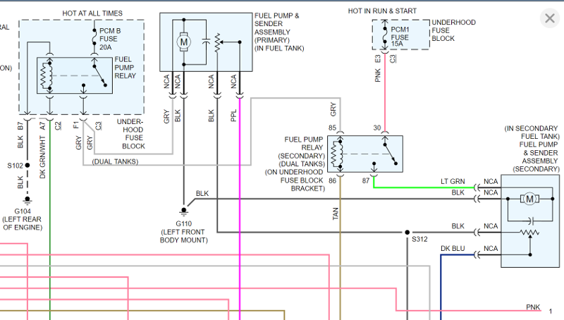
Relay, fuel pump, oil pressure switch - Hi everyone. Got a weird technical issue with a friend. He has an aftermarket fuel pump and harness along with an oil pressure switch. Relay is SPDT and wired accordingly. 30 is 12v 87 is power to pump 85 is trigger to oil pressure safety switch 86 is ground
The top no-load engine speeds differ and the following components are not included. Oil pressure switch (Hour meter will not function without an oil pressure switch) Correct engine wiring harness (to operate oil pressure switch) Oil drain pipe/hose. Solution. Solution: Remove and reuse the necessary components.
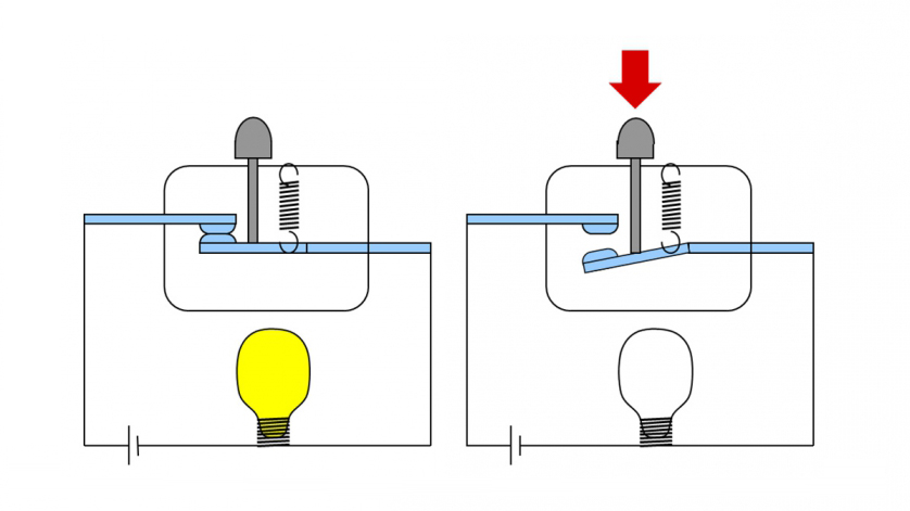
Figure 1. Engine oil pressure switch: 1. Washer for sealing, 2. Diaphragm, 3. Switch housing, 4. Connector, 5. Switch contacts (A normally open, B normally closed), 6.
Oil Pressure Switch Wiring Diagram – alco oil pressure switch wiring diagram, danfoss oil pressure switch wiring diagram, engine oil pressure switch wiring diagram, Every electrical arrangement is made up of various distinct parts. Each part ought to be set and linked to other parts in specific way. If not, the arrangement will not function as it ought to be.
specifications for typical wiring diagram. For external wiring diagrams, see Figs. 4 through 11. For applications using a 208 volt control circuit, it is suggested that one leg of the 208 volt circuit and a neutral or ground wire be used as a 120 volt source to power the time delay heater. When a P28 control is installed on a
Safety Interlock System Installation Instructions. Comprehensive installation instructions for Pressure Safety Switch Z-13061. A pressure switch should always be used in conjunction with the universal in-line electric fuel pump. ICC Motor Carrier Safety Regulations stipulate that the fuel pump must not continue to operate after the engine stops.
WIRING DIAGRAM COMPONENT LOCATIONS. When trying to locate a component in a wiring diagram and you don't know the specific system where it is located, use this handy component locator to find the system wiring diagram in which the component is located. Then, go to that system and locate the component within the wiring diagram.
A dimmer switch unit will definitely interfere with the functions of the oil pressure gauge and thus display incorrect readings. Step 7 - Test Double check if all corrections are in line with the wiring diagram in the service manual.
1) The Holley diagram DOES NOT show the vehicles start circuit to the solenoid, the wiring diagram only shows what is needed to add an oil pressure safety cutoff switch to an electric fuel pump. 2) The normally closed contact(N.C.) is closed in the shelf position(no pressure).
i have a 87 s10 with a 99 5.7 vortec/ engine harness... The harness was cut when i got it... it came with every other wire just not the 3 wire plug/wiring for the oil pressure sensor... i need to know where the 3 wires go.. the oil pressure sensor is from the 99 5.7 vortec the rest of the harness is finished... anyways the 3 wires are orange, tan and grey... if i member right the oil pressure.
Wiring Diagram. The user should plan to acquire and wear safety apparel during operation of this pressure washer. Safety apparel includes waterproof insulated gloves, safety glasses with side and top protection, and non-slip protective... Pump 13 Pressure Switch 20 Indicator Light 7 Water Inlet (feed tank) (high pressure)14 Water Outlet
Watch as Danfoss' own Will guides you through two different ways to wire an MP differential pressure switch, which is used to protect refrigeration compresso...









0 Response to "37 Oil Pressure Safety Switch Wiring Diagram"
Post a Comment