37 Dump Truck Hydraulic System Diagram
Hydraulic Power Units 12 VDC Dump Truck Snow Plow. Replacement Motors. Small Dump Hydraulic Pumps w/ Manual Valves. Air Shift Cylinder for Hydraulic Pumps w/ Manual Valves. H21-Series Hydraulic Bi-Rotational Pumps. Dual Shaft Hydraulic Pumps. Priority Flow Divider Valves. Selector Valves. Provides pressure relief to specific functions in your truck's hydraulic operations. 1 Spool Directional Control Valve. S direct flow where and when needed with reliable precision. Flow Control Valve. Lets you speed up or slow down a function, such as plowing or dumping, for more precise and smooth control. Electric Sectional Valve.
• “Dump Truck – Configuring “Hand Throttle” PTO 0”, page 115. form the basis of the hydraulic system. The pump, which provides the hydraulic pressure and flow to the motor, is the heart of the hydraulic system. All power take-offs covered by this chapter are available factory installed. Some variants can also be ordered.

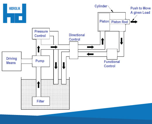
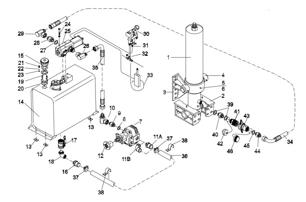
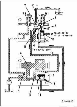
Dump truck hydraulic system diagram
Group 41 Hydraulically Actuated Clutch Clutch and Hydraulic Clutch System Pneumatic Servo Clutch engagement W4000857 When the clutch pedal is pressed, hydraulic pressure (10) increases and the reaction piston (3) is pressed in the direction of the arrow. This movement first shuts the control valves upper seat (4b) and then the air outlet duct (6). challenge so there is enough lift to tilt and dump the load. To accomplish this, the lift will have to accommodate the cylinder to transfer its force through the arms. The calculations predicted that a.5 gpm hydraulic pump would take 62 seconds to lift 500 pounds, dump and lower the load. Initial tests indicated a tilt goes to 39 degrees. H21 Series Hydraulic Gear Pump with Spine Shaft is a sturdy, durable bi-rotational pump that can be 2- or 4-bolt mounted. Direct Mount Small Dump Pump with Manual Valve. Mounts to a PTO for a compact source of hydraulic power for smaller applications. H50 Series Hydraulic Gear Pump with Spline Shaft.
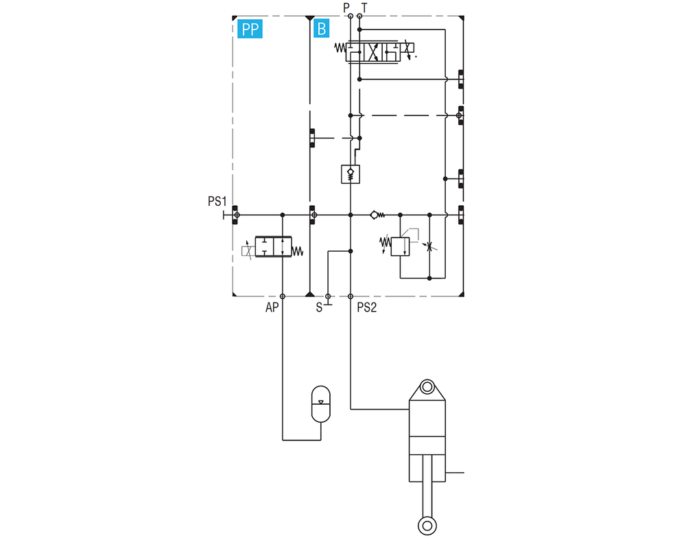
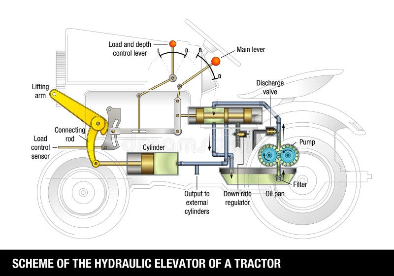
Dump truck hydraulic system diagram. Winch. The diagram shows a winch powered by a hydraulic motor. The directional control valve with built-in relief features optional flow control to control the speed of the winch. The hydraulic pump and motor must be matched to the torque requirements of the winch. 2. Dump Truck C102 . 2 Line Hydraulic System . PTO . Hydraulic Tank . Valve . PTO . HOIST . AUX . UP . DOWN . ON . OFF . PUMP . C102 T 1001 1-1/4” Hydraulic Steel Tubing T 1001 ASSY 1-1/4” Hydraulic Steel Tubing with the ends welded on AD 016 Weld Spud Fitting - 1-1/4” ID x 1” JIC HYDRAULIC TUBING Specifications The 1” & 1-1/4” steel tubing furnished for hydraulic drive mixers is cold drawn seam-less alloy 4130, soft annealed for bending A dump pump as used on a typical dump truck in N.A., is a combination of a hydraulic pump, a pressure relief valve and a directional control valve in one housing. The pump also has a pressure port that connects to the hydraulic cylinder and a larger port connected to the hydraulic reservoir.
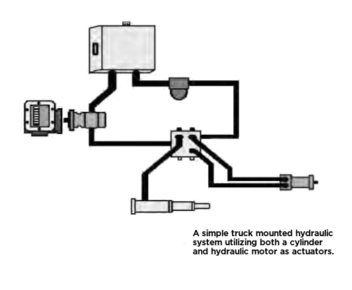
Relief Setting for Increased Lifting Power on A port Application: for Dump Truck, Unloading, Crane, Lifting, etc. Directions for use: According to hydraulic principle diagrams, with clean connecting hydraulic power unit and oil cylinder tubing According to the motor and the power of the electromagnetic valve marked characteristics( ac, dc. Dump pumps Pumps for refuse vehicles Dry valve pumps Live Pak™ pumps Section 4. a truck-mounted, or mobile, hydraulic system operates, what components make up the system, how they work, and why they sometimes fail to perform as expected. Our frame of reference is that of a leading manufacturer and challenge so there is enough lift to tilt and dump the load. To accomplish this, the lift will have to accommodate the cylinder to transfer its force through the arms. The calculations predicted that a.5 gpm hydraulic pump would take 62 seconds to lift 500 pounds, dump and lower the load. Initial tests indicated a tilt goes to 39 degrees. Caterpillar Forklift GP35N IC Pneumatic Trucks Electronic Sales Manual.pdf. 10.7Mb. Download. Caterpillar TM 5-3805-261-10 CAT 130G MIL Operation Manual.pdf. 5.7Mb. Download. Caterpillar Troubleshooting 3516B and 3516B High DisplacementEngines for Caterpillar Built Machines.pdf. 1.7Mb. Download.
Hydraulic Fluid moved into the system is supplied from the hydraulic reservoir (tank). Fluid displaced from the system flows back into the reservoir before being re-circulated through the system. The reservoir is designed to supply an adequate amount of fluid to operate the hydraulic system and to Heavy duty truck parts distributor specializing in aftermarket parts for the owner operator,. Typical 6 Wheel Air Brake System. These diagrams are provided for basic identification only. Always consult a professional technician to properly troubleshoot your system. September 7, 2016 By Mary Gannon. Muncie Power Products Inc.'s line of dump pumps is available in a three-line system option to help prevent the most common dump pump failure of high temperatures resulting from the pump being operated too long in neutral. A three-line system includes a separate line to return hydraulic oil from the cylinder. the dump body's safety equipment (the locking control lever, the deadman control, the body prop, the body-uplight and the backup alarm) is not in good working order. NEVER OPERATE A DUMP TRUCK UNLESS ALL OF THESE FEATURES ARE FULLY OPERATIONAL AND ALL OF THE VEHICLE'S SAFETY SYSTEMS (LIGHTS, BRAKES, WIPERS, ETC.) ARE IN GOOD OPERATING.
truck. Our THC's have it all: on-site service bays and complete hydraulic, pneumatic components and system coverage. Whether it's a component repair, replacement, or a complete system design and installation, Parker THC is the expert team you can rely on to keep your truck on the road.
The hydraulic pump is the component of the hydraulic system that takes mechanical energy and converts it into fluid energy in the form of oil flow. This mech...
central hydraulic systems. Flow ratings to 11 GPM and pressures to 4350 PSI. Product Brochures MP89-14 & MP93-03 K/L SERIES GEAR PUMPS These are proven performers in thousands of snow and ice control trucks. Simple, rugged, effective and reliable. Sizes, pressures, shaft and mounting options for virtually any central hydraulic system application.
HYDRAULIC SYSTEM FOR TRUCKS. United States Patent 3733818. FIG. 5 is a schematic diagram of a portion of a second embodiment of the invention; ... The coupling 118 is snapped together at the same time the spreader mechanism 120 is installed in the back of the truck dump body. When the coupling 118 is made to connect the line 116 to the ...
The economical Hydraulic Truck Conveyor mounts quickly and easily on all standard dump boxes to efficiently deliver material like sand, gravel, or hot asphalt where you want them, when you want them, without the expensive hand labor. Operating the HTC is a simple one-person job that can be handled from the truck cab.
H21 Series Hydraulic Gear Pump with Spine Shaft is a sturdy, durable bi-rotational pump that can be 2- or 4-bolt mounted. Direct Mount Small Dump Pump with Manual Valve. Mounts to a PTO for a compact source of hydraulic power for smaller applications. H50 Series Hydraulic Gear Pump with Spline Shaft.
packaging all the truck hydraulic, connector, and related hydraulic system components into a single wetline kit, our system offers the customer the following advantages & benefits: Chelsea Wetline System • High pressure hose with J.I.C. swivel fitting for quick and easy installation
Total Truck Parts, Inc. Typical Mobile Hydraulic System Schematics. Dump Truck and Trailer Installations. 2 Line Dump. 3 Line Dump. Other Trailer Installations. Combo II Kit. Ejector Trailer. Live Floor.
The truck has a 327 CID V-8 (although, as I later found out, a much preferred 292 CID L-6 engine was original), a New Process 5-speed manual transmission and a Chevy 2-speed rear axle. It also has the desired Garwood dump body and Heil hydraulic system. After initial contact and subsequent negotiations with the seller, I bought the truck.
Symbol Of Pump Used In Hydraulic System Circuit Diagram. 3. Hydraulic Motor. A hydraulic motor is a mechanical hydraulic actuator that converts hydraulic energy or hydraulic pressure into torque and angular displacement / rotation. Types Of Hydraulic Motors And Their Symbol Used in Hydraulic Circuit Diagram. 4. Hydraulic Cylinder
HYDRAULIC HOISTS 1-2 HYDRAULIC PUMPS 6-9 HYDRAULIC VALVES HYDRAULIC HOSES HYDRAULIC FITTINGS 3 4 5 HYDRAULIC RESERVOIR TANKS 10 POWER TAKE OFF (PTO) 11-12 WET KIT SYSTEMS 13-16 WET KIT ( DUMP TRAILER) QUOTE / ORDER SHEET 17. 8-5-265 Super Dump 73-40-110 SAT Hoist 7-3-120 SAT Hoist Hydraulic Operated Tailgate Lift Cylinder 7-4-135 SAT Hoist
Dump Trucks. A dump truck isn't much more complicated than the log splitter we saw previously. Dump trucks typically have one cylinder or a pair of cylinders that lift the bed. The only unique thing about these cylinders is that they often telescope, giving them a very long range of motion. Advertisement. 1..
Group 41 Hydraulically Actuated Clutch Clutch and Hydraulic Clutch System Pneumatic Servo Clutch engagement W4000857 When the clutch pedal is pressed, hydraulic pressure (10) increases and the reaction piston (3) is pressed in the direction of the arrow. This movement first shuts the control valves upper seat (4b) and then the air outlet duct (6).
A system including a hydraulic pump unloaded by a first system relief valve which is piloted by a remotely controlled two position directional valve. A second system relief valve in a hydraulic cylinder exhaust line is also of the pilot operated type. A manually operable valve in the truck cab pilots the second system relief valve to provide the operator precise manual control of cylinder.
HYDRAULIC SYSTEM FOR DUMP TRUCKS Filed Jan. 7, 1960 4 Sheets-Sheet 4 INVENTORH FRED BlszAN-rz q1/ARTHUR H. RUTH A Tfoxzugvs United States Patent O 3,094,359 HYDRAULIC SYSTEM FOR DUMP TRUCKS Fred Biszantz and Arthur H. Ruth, Galion, Ohio, assignors to Hercules Galion Products Inc., a corporation of Delaware Filed Jan. 7, 196i), Ser. No. 1,123 2 Claims.
Thank you everyone Welcome to the channel KING MECHANICAL MECHANISM - Dump truckA lot of mechanical mechanisms or are waiting for you to discoverfollowfacebo...
Ford f700 brake system diagram. Protect the metal parts in the system and rust will begin to form. F800 hydraulic parking brake pump service manual step by step bleeding process. This brake system it has lucas and girling brake system. Wagner brake products deliver improved oe design products to the aftermarket giving you the capability to.












0 Response to "37 Dump Truck Hydraulic System Diagram"
Post a Comment