44 garage door sensor circuit diagram
Garage Door Sensors Wiring Diagram (PDF) - proplist.farislee garage-door-sensors-wiring-diagram 1/1 Downloaded from proplist.farislee.com on May 16, 2022 by guest Garage Door Sensors Wiring Diagram When somebody should go to the ebook stores, search start by shop, shelf by shelf, it is really problematic. This is why we provide the book compilations in this website. Linear Garage Door Opener Wiring Diagram Linear Garage Door Opener Wiring Diagram Linear/Allstar > Wire Diagrams These wire diagrams are for current and previous models. To be sure you receive the Residential Door Operator - Wiring Diagrams 2GIG-GDR 2GIG Garage Door Remote Module Discontinued. Garage Door Opener Linear GD00Z-4 Installation Instructions .
15 (Effective) Ways On How to Bypass Garage Door Sensors How to Bypass Garage Door Sensors Safely 1. Make Sure the Door is Either All the Way Closed or the Opening is Propped Up From Underneath 2. Locate and Drag Down the Manual Release Cord 3. Remove Your Props and Close the Door Gently 4. Cut Off the Power to the Safety Sensors 5. Remove the Sensors from the Door Assembly 6.

Garage door sensor circuit diagram
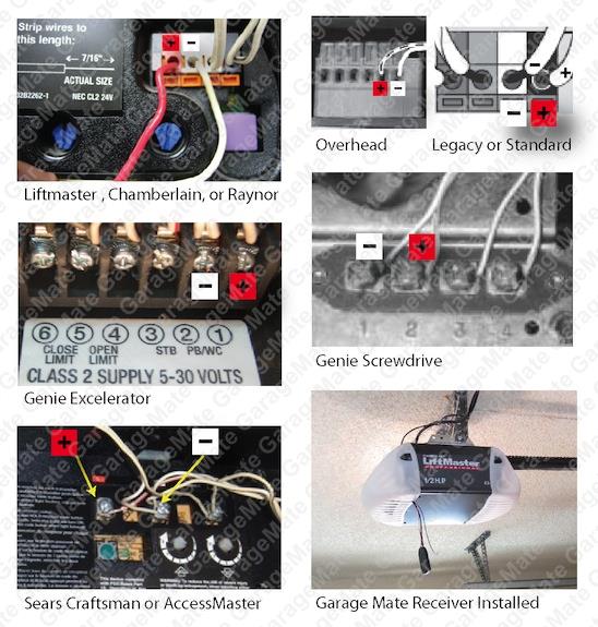
Door Sensor Circuit - ElectroSchematics.com Assemble the circuit on a small PCB and enclose in a suitable box. Fix the Hall sensor (HS1) at the corner of door frame and the magnet on the door, keeping its south pole (S) oriented towards the marked side of HS1. Align the Hall sensor and magnet such that when the door is closed, LED1 lits steadily. Notes: How to wire safety sensors to a garage door opener ... Strip 7/16-inch of insulation from each of the two wires on each sensor—each sensor has two wires, a solid white one and one white with a black stripe, for a total of four wires. Twist together the two white-with-black-stripe wires from both sensors. Twist together the two white solid wires from both sensors. Garage Door Obstruction Sensor Repair : 9 Steps (with ... Figure 2 is the wiring diagram for the sensor's connection to the controller. The white terminal is ground and the gray terminal is a 6.3 Volt supply. Figures 3 and 4 are the waveforms between the gray and white terminals for a working sensor. The period of the sensor pulse is about 6.4 milliseconds, while the pulse width is about 440 microseconds.
Garage door sensor circuit diagram. Garage Door Safety Sensor Wiring Diagram - Free Wiring Diagram Collection of garage door safety sensor wiring diagram. A wiring diagram is a streamlined traditional photographic depiction of an electric circuit. It shows the parts of the circuit as streamlined forms, and the power and also signal links between the gadgets. A wiring diagram usually provides information concerning the family… How To Bypass Garage Door Sensors A Simple 1, 2, 3 ... In those rare instances it is vital that the issue is addressed and that we do not just bypass the garage door sensors. These scenarios bring us to step one. Step 1: Check Garage Door For Physical Obstructions Your garage door opener is smart enough to not allow it to close when something could become damaged, or worse injured. Wiring Diagram Garage Door Sensor .pdf - skeezick ... wiring-diagram-garage-door-sensor 1/1 Downloaded from skeezick.desertowlgames.com on May 17, 2022 by guest Wiring Diagram Garage Door Sensor Right here, we have countless ebook Wiring Diagram Garage Door Sensor and collections to check out. We additionally manage to pay for variant types and with type of the books to browse. Installing Safety Sensors on a Garage Door Opener | Home ... Manufacturers now supply safety sensors with the garage door opener system so the door cannot accidentally crush a person or property; the sensors cut off the closing circuit to the system and ...
Garage Door Sensor Wiring Diagram Collection - Wiring ... garage door sensor wiring diagram - What is a Wiring Diagram? A wiring diagram is a straightforward visual representation in the physical connections and physical layout of the electrical system or circuit. It shows how a electrical wires are interconnected and can also show where fixtures and components might be coupled to the system. HONDA - Car PDF Manual, Wiring Diagram & Fault Codes DTC Hello, I’am looking for a steer wheel electrical circuit diagram for my 2004 Chevy suburban 5.3L 4wd Z-71 series 1500 CK-15906. Looking for the pin out diagram so that I can replace my wires back into the proper holes. Thank you for any help. #509. Edwin tejeda (Tuesday, 22 March 2022 19:41) Craftsman Garage Door Opener Sensor Wiring Diagram If the garage door is hard-wired into the electrical circuit, turn off the circuitLocate the bell wire that connects the wall switch to the garage door opener. Follow the bell wire to the wall switch. Loosen the mounting screws and remove the switch from the schematron.org a new wall switch onto the wall in the desired location. Wiring Diagram Garage Door Opener Sensors (PDF) - chatbot ... wiring-diagram-garage-door-opener-sensors 12/20 Downloaded from chatbot.euroresidentes.es on May 16, 2022 by guest designs and enhancements, plumbing and electrical wiring, energy-saving lighting options, home safety and security measures, and much more. Guide to Digital Home Technology Integration Quentin Wells 2008-10-14 The most complete, up-
Liftmaster Garage Door Sensor Wiring Diagram If you look at the wires from the sensors you will find one wire from each sensor is solid white and the other is white with a black tracer. View and Download Chamberlain DH wiring diagram online. Locksensor (D1 Wiring). DH Accessories pdf manual download. Also for: Dj, Liftmaster dh, Liftmaster dj, Liftmaster dh/j. Sensor will stop the operator. Garage Door Opener Electric Eye signal is observed: the white/black wire is 6V above the white wire for about 5.5 ms, then falls close to 0V for about 0.5 ms. This suggests that the opener is supplying 6V through a resistor -- the receiver is "pulling" the voltage to (near) 0V briefly and periodically. One cannot expect the 100+ Microcontroller Based Mini Projects Ideas for ... Aug 01, 2016 · When the RFID tag, which is carried by the user or fixed to the car, approached the garage door, the microcontroller triggers for an automatic opening of the door. Secure Garage System Using License Plate Recognition Technique: There are many automatic garage door system. Most of them employ any of the wireless communication technique but ... Small FM Radio Circuit - ElectroSchematics.com Apr 22, 2016 · The circuit works off a small 4.5 volt battery or two 3.6 volt Lithium button cells. The fm receiver section has two RF transistors T1 and T2 to detect the Frequency Modulated signals. Coil L1 and the trimmer capacito form the tuned tank circuit to tune the receiver to the best FM station with strong signals.
Garage Door Sensor Issue?? - Windows and Doors - DIY Chatroom Home Improvement Forum
Wiring diagram for 1/2HP garage door opener, wire ... The high voltage wire harness has 6 wires 1 blue, 1 red, 1 orange, 1 black, and 2 white wires, that connect to the logic board The first white wire connects to the first silver prong on the terminal block The black wire connects to the gold prong on the terminal block The red and the blue wire go to the capacitor
28 Liftmaster Garage Door Sensor Wiring Diagram - Free Wiring Diagram Source
Chamberlain Garage Door Sensor Wiring Diagram Collection ... chamberlain garage door sensor wiring diagram - What is a Wiring Diagram? A wiring diagram is an easy visual representation with the physical connections and physical layout associated with an electrical system or circuit.

Sears Garage Door Opener Safety Sensor Bypass | Dandk Organizer
Craftsman Garage Door Opener Sensor Wiring Diagram ... Craftsman Garage Door Opener Sensor Wiring Diagram Written By admin Monday, February 14, 2022 Insert the jumper wire into the wall control terminals on the garage door opener to see if the garage door moves. If you look at the wires from the sensors you will find one wire from each sensor is solid white and the other is white with a black tracer.
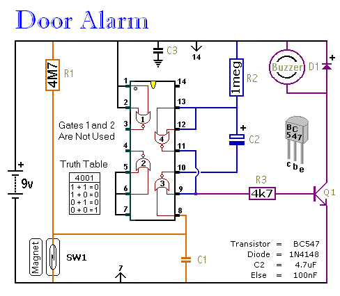
A Simple Shop-Door Alarm circuit diagram and instructions
IR beam garage door circuit | Electronics Forum (Circuits ... Circuit details if you're interested: It appears the transmitter, utilizing a common IR LED, is driven by a transistor driver on the low side (NPN) which is driven by the output of an oscillator involving the LM2903 comparator. The oscillator is made so that the output consists of about 20 short pulses of 5 ms each that occur every 100 ms or so.
Car Door Sensor 1 - CircuitLab
Genie Garage Door Sensor Wiring Diagram Free Picture (PDF ... genie-garage-door-sensor-wiring-diagram-free-picture 2/30 Downloaded from mage2.colgin.com on May 17, 2022 by guest and research skills. The P-47 fighter pilot turned engineer, inventor, educator, and author found himself immersed in the Cold War race to the moon, developing cutting-edge technology, instructing future astronauts in aerodynamics and

Projects on Password Based Door Lock System Using Microcontroller
Garage Door Closure Sensor - ControlByWeb When the magnet is within proximity of the sensor switch, it will apply a voltage to the digital input, turning it 'On.' When the input changes, ControlByWeb module can be configured to send email/text alerts, control remote relays (for alarms at a remote location), and/or log events. Garage Door Sensor Wiring Diagram (N/O Circuit)
0 Response to "44 garage door sensor circuit diagram"
Post a Comment