38 another term for a network diagram is a deployment diagram.
Cellular network - Wikipedia A cellular network or mobile network is a communication network where the link to and from end nodes is wireless.The network is distributed over land areas called "cells", each served by at least one fixed-location transceiver (typically three cell sites or base transceiver stations).These base stations provide the cell with the network coverage which can be used for transmission … JupiterOne Data Model - AskJ1 Community What does this look like? The JupiterOne Data Model is a reference model used to describe digital resources and the complex interconnections among all the resources in a technology organization as an entity-relationship graph. The data model is defined by a set of Entities and their Relationships. It represents a reference model, not a strict ...
Class Diagram For Client Server Application An icon handler can arrange the default and one the icon for every particular file. The looking of a component diagram is everything show the relationship between different components in these system. Deployed the applications in development and staging environments. In a deployment diagram, in this badge, assign a time estimate to particular task.

Another term for a network diagram is a deployment diagram.
› pages › er-diagramsER Diagram (ERD) - Definition & Overview | Lucidchart Database troubleshooting: ER diagrams are used to analyze existing databases to find and resolve problems in logic or deployment. Drawing the diagram should reveal where it’s going wrong. Business information systems: The diagrams are used to design or analyze relational databases used in business processes. Any business process that uses ... System Design — UML Deployment Diagram | by JIN | InterviewNoodle | May ... The deployment diagram represents the deployment view of a system. It is usually used by system engineers. Basic Elements. Node; It represents hardware resources in a runtime computer system. OBM deployment - docs.microfocus.com An OBM deployment consists of proprietary servers and components, data providers, and third-party servers, such as database and web servers, that you set up in your environment. The following diagram provides an overview of an OBM enterprise deployment. To get details about a component, click the corresponding box in the image. Deployment strategy
Another term for a network diagram is a deployment diagram.. Different UML Diagrams - Purpose and Usage - Edraw UML Deployment Diagram Purpose A deployment diagram is a type of diagram used in UML to describe the hardware components used in system implementations and the execution environments and artifacts deployed on the hardware. The Art of Crafting Architectural Diagrams 04.08.2017 · Architectural diagrams can be useful tools for documenting and communicating the design of a system. They must be self descriptive, consistent, accurate enough and connected to the code. Applying ... Browse Articles | Nature 24.05.2022 · The patent system assumes that inventors are human. Inventions devised by machines require their own intellectual property law and an international treaty. Cloud Deployment Models - GeeksforGeeks The cloud deployment model identifies the specific type of cloud environment based on ownership, scale, and access, as well as the cloud's nature and purpose. The location of the servers you're utilizing and who controls them are defined by a cloud deployment model. It specifies how your cloud infrastructure will look, what you can change ...
What is a Deployment Diagram | Deployment Diagram Tutorial A deployment diagram is a UML diagram type that shows the execution architecture of a system, including nodes such as hardware or software execution environments, and the middleware connecting them. Deployment diagrams are typically used to visualize the physical hardware and software of a system. Deployment Diagram Tutorial | Lucidchart In this case, the deployment diagram describes the physical deployment of information generated by the software program on hardware components. The information that the software generates is called an artifact. This shouldn't be confused with the use of the term in other modeling approaches like BPMN. kubernetes diagram generator | Mahonnathaa The master node is the entry point for all kind of administrative tasks everywhere. Specify pod definitions to the each pod Hyperglance: Visualize & Document Kubernetes architecture diagram above you specify! Diagrams the way you prefer ; as a global diagram, Kubernetes coordinates lots of microservices that together a... Detail Instructions for Drawing Class Diagrams In What Is Uml This type of deployment diagram - not formally defined in UML 2.5 - can be called a network architecture diagram. node, switch, router, load balancer, firewall, communication path, network segment, backbone.
azure deployment architecture diagram - danieyehospital.com Hybrid deployment . Step 1: Open Azure Icons. Use of Terraform allows us to easily achieve parity in development, test, production environments. Machine Learning will in turn pull metrics from the Cosmos DB database and return them back to the client. Use case diagram of course registration system 19 612 7.4 PROCEDURE: Step - 1: Create an Account (or) Sign Up Step - 2: Login with username and password Step - 3: After login into an account, select any Course that you want to study and Print it to proceed as shown below 37. Here you can print either of these to start learning the course. CS2113/T - Textbook Chapter : Modeling A model is a representation of something else.. A class diagram is a model that represents a software design.. Class diagrams. A class diagram is a diagram drawn using the UML modelling notation. An example class diagram: A model provides a simpler view of a complex entity because a model captures only a selected aspect. This omission of some aspects implies models are abstractions. Duo Two-Factor Authentication with RADIUS and Primary ... - Duo … 19.04.2022 · To integrate Duo with your VPN or other device, you will need to install a local proxy service on a machine within your network. This Duo proxy server also acts as a RADIUS server — there's usually no need to deploy a separate additional RADIUS server to use Duo.
uml - Having trouble with deployment diagram - Stack Overflow Just putting three boxes in with the text MVC is rather pointless. You might show details as to where a MVC pattern is used concrete. But I guess, this should go elsewhere (in the class design). Your deployment diagram should just show how the components are deployed (i.e. on which hardware you have which software/library). Share

Conceptual Marketing Corporation - ANALYSIS INFORMATION FROM A EUROPEAN PERSPECTIVEPETROFILM ...
› crafting-architectural-diagramsThe Art of Crafting Architectural Diagrams - InfoQ Aug 04, 2017 · For example, adding components to an architectural context diagram or classes to a deployment diagram might diverge the purpose of the diagram itself. When creating a diagram, try to stick with ...

How to create static diagrams in Unified Modeling Language Deployment A deployment diagram describes a component (s) in terms of its hosting artifacts. It also describes how communication is facilitated among the various deployment hosts. Deployment example Figure 8 is a deployment diagram that describes three hosting environments according to the stereotype <>.

Deployment Diagram: UML Tutorial with EXAMPLE - Guru99 The deployment diagram maps the software architecture created in design to the physical system architecture that executes it. It maps software pieces of a system to the hardware that are going to execute it. Deployment diagram visualizes the topological view of an entire system. Nodes and artifacts are the essential elements of deployment.

What is the H-R diagram, and how is it useful? - Quora An Entity Relationship (ER) Diagram is a type of flowchart that illustrates how "entities" such as people, objects or concepts relate to each other within a system. ER Diagrams are most often used to design or debug relational databases in the fields of software engineering, business information systems, education and research.
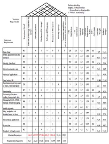
Quality Function Deployment in the Mobile Phone Industry
ER Diagram (ERD) - Definition & Overview | Lucidchart ER components can be equated to parts of speech, as Peter Chen did. This shows how an ER Diagram compares to a grammar diagram: Common noun: Entity type. Example: student. Proper noun: Entity. Example: Sally Smith. Verb: Relationship type. Example: Enrolls. (Such as in a course, which would be another entity type.) Adjective: Attribute for entity.

Assignment 2: Designing UML Diagrams - Study.com UML is a standard language used to both visualize elements within a system and provide a picture of the software's design. In this assignment, you will develop a full UML suite. You will be...

es.digi.com › blog › postWhat Is 5G Network Architecture? | Digi International Mar 19, 2021 · The 5G network architecture diagram below illustrates how these components are associated. 4G Architecture Diagram. When 4G evolved from its 3G predecessor, only small incremental changes were made to the network architecture. The following 4G network architecture diagram shows the key components of a 4G core network: Source: 3GPP
0 Response to "38 another term for a network diagram is a deployment diagram."
Post a Comment