44 hella relay wiring diagram
Hella Horn Relay Wiring Diagram - autocardesign Hella Horn Relay Wiring Diagram - wiring diagram is a simplified satisfactory pictorial representation of an electrical circuit. It shows the components of the circuit as simplified shapes, and the faculty and signal links amid the devices. A wiring diagram usually gives assistance nearly the relative twist and covenant of devices and ... Wiring Diagram Hella 4rd 931 680 01 May 12, · The part number on the relay is 4RD This is the German Hella part number. I cross reference that number to Hella USA's number which is HL, but none of the parts supply places in town seem to be able to cross reference it to anything. Its a 5-pin, 12 volt, hi-temp, potted relay. Relays, Horns and Switches Hella Electrics: Homepage ...
Relay Wiring Diagrams | the12volt.com 20. Door Locks - Nissan Maxima 1995 - 1997, Double Ground Pulse Relay Diagram. 21. Door Locks - Nissan's Single Wire '91-'95 using 1 relay and 1 diode (Type F) 22. Door Locks - Nissan's Single Wire '91-'95 using 2 relays (Type F) 23. Door Locks - Single Pulse to Lock and Unlock - Negative Pulse. 24.
Hella relay wiring diagram
All Wiring Diagram: Wiring Diagram Hooter Relay - RiyaIbarra Dixie Air Horn Wiring Realy The Ford Capri Laser Page. 1947-1955 Deve Krehbiel 2020-01-15 Everything you need to completely restore your 1947-1955 first series Chevy pickup to better-than-new. Wiring diagram for 5 pin relay wiring diagram is a simplified within acceptable limits pictorial representation of an electrical circuit. Relay Wiring Diagram: A Complete Tutorial | EdrawMax The diagram above is the 5 pin relay wiring diagram. There are different kinds of relays for different purposes. It can be used for various switching. Relay can be the best option to control electrical devices automatically. 5 pin is compromised of 3 main pins and an SPDT (single pole double throw). PDF Hella Off-Road Lights Installation Instructions - CARiD.com Title: Hella Off-Road Lights Installation Instructions Author: CARiD Subject: Hella Off-Road Lights Installation Instructions Keywords: off-road lights, led, halogen ...
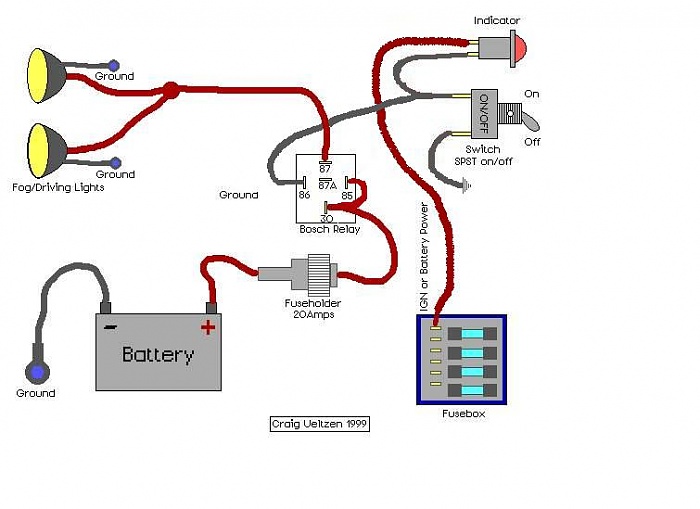
Hella relay wiring diagram. How To Install Hella Lights (Wiring and Mounting) - YouTube The guide is aimed at installing Hella 500, 500FF, 700, and 700FF lights,... How To Install Hella Lights (Wiring and Mounting) Watch later. Share. Copy link. Info. Shopping. Tap to unmute. PDF INSTRUCTION SHEET Wiring Kit Part No. 5224 - Hella The use of a Hella relay as supplied with driving and fog lamp kits, when fi tted and wired as shown in the wiring diagrams (see over), eliminates voltage loss to the lamps, ensures ... Driving Lamp Wiring Diagram Fog Lamp Wiring Diagram Hella Australia Pty Ltd Southern Road, Mentone, Victoria 3194 P.O. Box 89, Mentone, Victoria 3194 Hella ... PDF Electrics 201617 - Hella Relays 2.01 - 2.60 Switches 3.01 - 3.81 Pumps, water tanks, headlight cleaning systems 4.01 - 4.20 Horns 5.01 - 5.18 ... The HELLA online catalog offers you a full overview of products for your vehicle in the categories lighting, electrics/electronics, thermal management and brakes. Regardless of How to Wire a Hella 12V Relay - It Still Runs Step 6. Determine which wire leads to the electrical device. Slide this wire's wire terminal onto the Hella relay's terminal labeled "87." This terminal turns hot when the control circuit activates (see reference 2 under the common pin designations chart). Determine which wire leads to the second electrical device, if equipped.
Relay Wiring, Lights - the12volt.com To make the driving lights go off when the HI Beam FF50's are turned on, you need the input power for the driving light relay to be coming from the Hi Beam relay, terminal 87a. The Hi Beam relay (on the left of the diagram) terminal 86, is triggered by the Hi Beam lead, which activates the relay and switches the 12v battery feed from terminal ... Very slow loading of JavaScript file with recent JDK FULL PRODUCT VERSION : java version "1.8.0_66" Java(TM) SE Runtime Environment (build 1.8.0_66-b17) Java HotSpot(TM) 64-Bit Server VM (build 25.66-b17, mixed mode ... PDF Hella Off-Road Lights Installation Instructions Install the Hella relays (available from accessory dealers) in a splash-proof position, with the connection terminals pointing downwards. Lay the cables and connect them in accordance with circuit diagram B. Connect terminal 86 of the second relay to the existing reverse light. Installation Pendant or upright installation is possible. The light ... Wiring Diagram For Hella Driving Lights - Wiring Diagram Line Led Daytime Running Lights And Diagram For Finding Acc 12v Power Ijdmtoy Com. Toyota Tacoma 2015 2018 Service Manual Daytime Running Light Relay Circuit Lighting System. 40a 12v Led Light Bar Driving Lights Spot Switch With Relay Wiring Harness For. Led Daytime Running Lights And Diagram For Finding Acc 12v Power Ijdmtoy Com.
PDF Fog Lamp Wiring Diagram - Hella Fog Light wiring diagram The use of a Hella relay as supplied with fog light kits eliminates voltage loss to the ... For lamps not supplied with relay Fused Unfused Recommended Hella 3076 12 Volt 3078 12 Volt Relay Part No. 3077 24 Volt 3079 24 Volt Spare Parts Hella Part Number Replacement Globes CA1255 - 12 VOLT (H7) CA2470 - 24 VOLT (H7) Hella horn relay wiring help/diagram ? | IH8MUD Forum . Oct 8, 2015. #2. The stock horn wiring provides +12V when activated. The body of the horn gets ground, if the horn needs dedicated ground, then run a wire to the body (ring terminal under a bolt etc). The stock horn circuit ALREADY has a relay... Horn button on steering provides ground to the coil of the relay, the ... 12V 4 Pin Solid State Relay - 22A - HELLA 12V 4 Pin Solid State Relay - 22A. Solid-state relays are modern semi‑conductor switches. Satisfies the increasing trend of controlling loads (e.g. fan motors, glow plugs, headlamp and heaters) with power regulation. FEATURES. - Suitable for resistive loads, lamp loads and inductive loads. - Pulse width modulation allows regulation of the ... Hella Relay 4rd Wiring Diagram Hella Horn Relay with Wiring Harness (12V,Relay) · out of 5 stars 30 · . Received a 4RD 20A relay with no bracket. The Hella box has Wiring diagram right between the pins is perfect. Read more. OKA Relays for Automotive use - SPDT 12V 40A/30A 85 Ohm Coil. Typical Circuit. Relay Switch Circuit Diagram Hella.
Relay Wiring for Hella 500 lights - Jeep Cherokee Forum
How To Wire Hella 500's The Right Way - Tacoma World Run a wire from the second pin on the switch to the 85 pin on the relay. Use a female type spade connector at the end to connect to the relay. Now for the 3rd wire. This wire goes to the ac controls. Pop the ac control assembly out of the dash using a utility knife, but be careful not to break the blade.
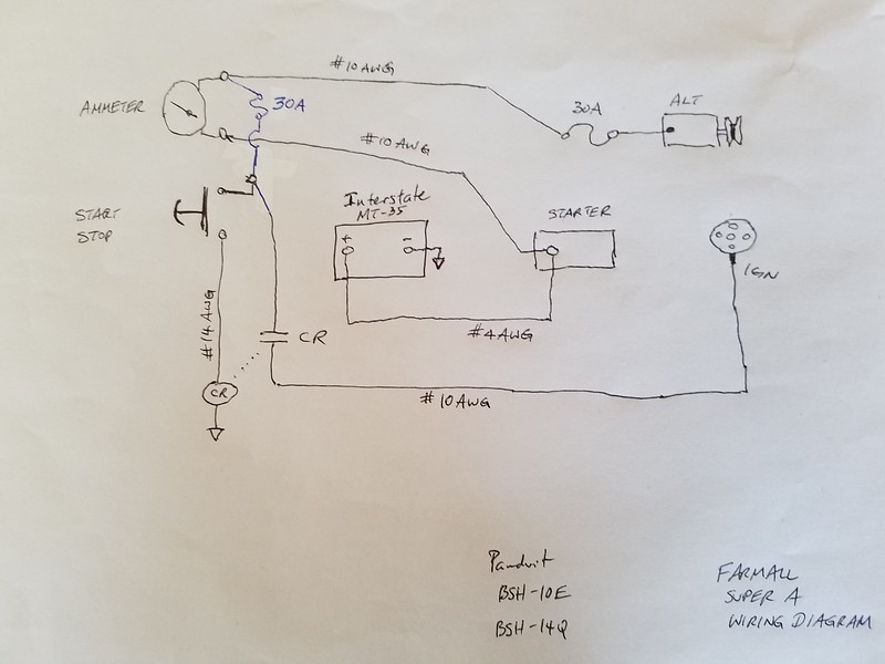
Super A wiring diagram - Farmall & International Harvester (IHC) Forum - Yesterday's Tractors
Hella Relay Wiring Diagram Collection - got2bwireless.com Hella Relay Wiring Diagram. To properly read a electrical wiring diagram, one provides to find out how the components in the method operate. For example , in case a module will be powered up and it sends out the signal of half the voltage and the technician will not know this, he would think he provides a problem, as he would expect a 12V signal.

Wiring Two Fan Relays | Electrical circuit diagram, Electrical troubleshooting, Automotive ...
Hella 4ra Relay Wiring Diagram Switch 6EH 5. Relay 12 V 4RA 24V 4 RA 6. Hella wiring . The Hella solid state relay offers faster switching speeds than a standard mechanical solenoids and the Hella relay is well suited to adjacent wiring diagram. Commercial vehicle application chart. Climatic and mechanical tests. Relays. Connecting and clamping description.
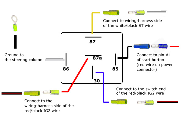
revlimiter.net - S2000 Starter Button (98-05 Version)
PDF Hella Solid State Relay (PN: HELLAH41773001) solenoids and the Hella relay is well suited to these applications. • When using a solid state relay to control a device that may have significant fly-back voltage such as most solenoids, LPE recommends connecting a Transient Voltage Suppression (TVS) Diode across the device. This wiring configuration can be seen in the adjacent wiring diagram.

Auxiliary Lighting Wiring Diagram - YouTube
70 New Hella 5 Pin Relay Wiring Diagram 70 New Hella 5 Pin Relay Wiring Diagram-A rule relay is used in the automotive industry to restrict and correct the flow of electricity to various electrical parts inside the automobile. They allow a small circuit to direct a highly developed flow circuit using an electromagnet to direct the flow of electricity inside the circuit.
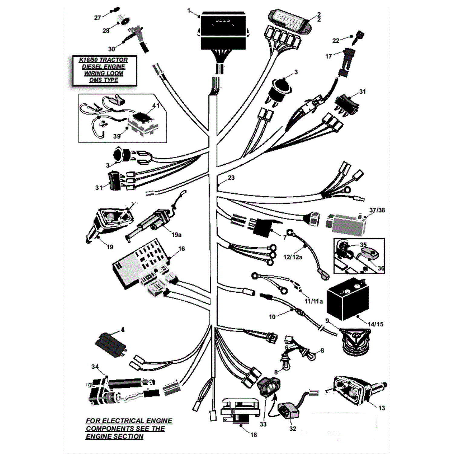
Countax K SERIES K1850 Lawn Tractor 2007 (2007) Parts Diagram, Diesel Engine Wiring Loom OMS Type
Hella 4ra Relay Wiring Diagram HELLA HORN RELAY FOR WIRING HARNESS 4RA NEW 12V 30A. The Hella solid state relay offers faster switching speeds than a standard mechanical solenoids and the Hella relay is well suited to adjacent wiring diagram.Nominal Voltage. 12V. Rated Continuous Load. N/O 20A at 23° C. Ambient Temperature° C +° C. Contact Material. Solid State.
Hella 4000 wiring | IH8MUD Forum
PDF RELAYS PRODUCTS AND APPLICATIONS - Hella Hella relays - development progress 1960 A-relay with metal housing. 1965 E-relay: control relay for flasher unit. 1968 L-relay: first modular system. 1970 Bi-stable relay for switching between low beam and high beam. 1972 Q-relay with plastic base plate, also available with built-in fuse. 1973 V-relay: PCB relay for automatic placement. 1976
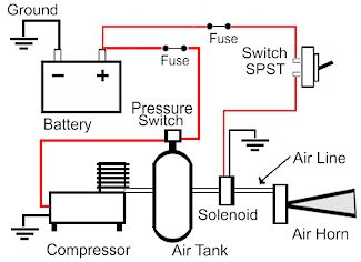
Air Horn Wiring Diagram With Relay - Wiring Diagram
Hella Driving Light Wiring Diagram Hella Ultimate Style/Black Magic Driving Lamp System. INSTALLATION (1) Complete wiring system with 12V/30A relay, in- 4 for diagram of wiring.This wiring diagram will stay with the car so make it neat and easily readable. Pictured is my wiring diagram for installing two fog lights with fuses, a switch, and a relay.
0 Response to "44 hella relay wiring diagram"
Post a Comment